
Decentralized Platoon Management and Cooperative Cruise Control
of Autonomous Cars with Manoeuvre Coordination Message
Reza Dariani
a
, Giovanni Lucente and Julian Schindler
b
Institute of Transportation Systems, German Aerospace Center, Lilienthalplatz 7, Braunschweig, Germany
Keywords: Cooperative Trajectory Planning, Platooning, Cacc, Vehicle Automation, Manoeuvre Coordination Message.
Abstract: Recent development of Vehicle-to-Vehicle (V2V) technologies enables the vehicles to communicate with
each other and coordinate their manoeuvres. With such technologies an Advanced Driving Assistance System
(ADAS) such as Adaptive Cruise Control (ACC) can be pushed to another level in conditional and highly
automated vehicles, i.e. a network of cooperative connected vehicles in the form of Cooperative ACC (CACC)
or even a platoon. In this paper, based on V2V communication between automated vehicles by using
Manoeuvre Coordination Message (MCM), a decentralized platoon management is designed and
implemented to manage the platooning state of each vehicle and when the vehicles are in a platoon or joining
one, a cruise controller is designed and implemented to guarantee the desired headway to a preceding vehicle.
1 INTRODUCTION
An average driver has a very slow reaction time,
around 2.3 seconds (McGehee, Mazzae, & Baldwin,
July 2000). Driver errors play the most important
role, with 94%, in a crash of light vehicles, based on
the research done at National Motor Vehicle Crash
Causation Survey (NMVCCS) (Transportation,
March 2018). That is why the modern vehicles are
equipped with a high number of sensors and
Advanced Driver Assistance Systems (ADAS) to
inform, warn and even intervene in critical driving
situations. As further development of such systems,
the partially-automated and automated driving
functions aim to take the driver partially or
completely out of the driving process.
It is not far from imagination to think that in near
future the traffic network will be a mixture of cars
with different levels of automation. The conditional
and highly automated vehicles (SAE3 & 4 level)
(SAE International, 2021) will soon be on the road.
These cars not only can monitor and sense the
environment and plan and drive a trajectory, they can
also cooperate with each other as well as with C-ITS
infrastructure. This cooperation enabled by
communication technologies, can be used to
a
https://orcid.org/0000-0002-1091-8793
b
https://orcid.org/0000-0001-5398-8217
coordinate the manoeuvre between automated
vehicles. This coordination may be in the form of
connected cruise control or a platoon. Vehicle
platooning in general is a method, in which a string of
vehicles drives together while keeping certain inter-
vehicular distances (or time-headways) by using
various types of sensors and ways of communication,
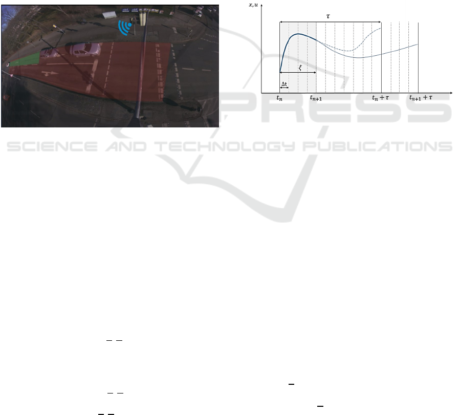
see Figure 1, which results in a more optimal use of
the traffic network.
This paper describes the aspects of vehicle
automation and focuses particularly on a proposed
trajectory planning module and decision-making
module, see Figure 2. The decision-making module
deals mostly with cooperation aspects of vehicle
automation and it also analyses the road geometry,
other road users and information received via
communication and defines a strategy for the
trajectory planning module. A platoon management
module in the form of state machines has been
designed as part of the decision-making module
which deals with platooning vehicle states. How one
car can form a platoon with another car and under
which conditions that is possible; are the questions
that can be answered through platoon management or
platoon logic concepts. Based on the defined strategy
from the decision-making module, the trajectory
planner plans an optimal trajectory and delivers the
Dariani, R., Lucente, G. and Schindler, J.
Decentralized Platoon Management and Cooperative Cruise Control of Autonomous Cars with Manoeuvre Coordination Message.
DOI: 10.5220/0011043400003191
In Proceedings of the 8th International Conference on Vehicle Technology and Intelligent Transport Systems (VEHITS 2022), pages 281-289
ISBN: 978-989-758-573-9; ISSN: 2184-495X
Copyright
c
2022 by SCITEPRESS – Science and Technology Publications, Lda. All rights reserved
281

vehicle actuators input to the vehicle controller. The
vehicle controller itself consists of several feedback
and feedforward controllers to guarantee that the
vehicle follows the planned trajectory. Another
important part of the decision-making module, is the
cooperative cruise controller which calculates a
velocity for the vehicle based on the information
received about the preceding vehicle via V2V
communication. Driving with that velocity results in
driving with shorter headway to the preceding vehicle.
The majority of the research on the idea of
platooning has been conducted in a highway-based
situation. However, recently the research work has
turned towards platooning in urban areas, where
platooning is mostly linked to efficient intersection
passing rather than reducing air drag. Although
requiring a high amount of flexibility, the idea of
urban platooning has already been tested in public
traffic (Schindler, et al., 2020) (Dariani & Schindler,
2019). However, it is still far from being normalized
or standardized. The communication network needed
for cooperation in this paper is only based on the
preceding vehicle and no other information such as
leader information is required. That makes the
cooperation very dynamic especially in urban areas in
which the string of the vehicles mostly does not have
a common destination and the vehicles drive together
only for few intersections. In this case forming and
resolving a platoon is very dynamic and adaptive to
urban area scenarios.
Figure 1: String of vehicles driving with CACC.
The main focus on this paper is on the trajectory
planner and the decision making. Although the
decision-making modules focuses on many aspects
such as behaviour and intention prediction of other
participants as well as analysing road geometry
(Dariani & Schindler, 2019), in this paper only
platooning related functionalities of the decision-
making module are discussed.
The outline of the paper is as follows, chapter 2
describes the vehicle automation and briefly explains
the trajectory planner and decision-making module.
In Chapter 3 the trajectory planner is explained.
Chapter 4 is about the decision-making module with
the focus on the platoon management module and the
cruise controller. In Chapter 5 the functionality of the
designed algorithms has been proven in simulations
and tests in public traffic in a complex urban area, and
finally Chapter 6 is conclusion.
2 VEHICLE AUTOMATION
The Automated Driving Open Research (ADORe)
developed by the Institute of Transportation Systems
of the German Aerospace Center (DLR), also
available open source (Hess, et al., 2017), is a
modular software library and toolkit for decision
making, planning, control and simulation of
automated vehicles has been used for this work, see
Figure 2. As the same software is used in simulation
and in research vehicles, the simulation experiments
are very close to reality. Although many modules
remain unchanged in this work such as Navigation,
Controller, Data Model, etc., several modules have
been completely changed or modified explicitly for
this research work, such as Decision-Making,
especially the platoon management module,
Trajectory Planning and cruise controller.
Figure 2: ADORe modular architecture.
For Trajectory planning an optimal control
approach is used which makes the planned trajectory
the solution of a nonlinear optimization problem. One
powerful method to solve a sequence of nonlinear
Optimal Control Problems (OCP) is Sequential
Quadratic Programming (SQP). The Newton method
or quasi-Newton method finds a point where the
gradient of the objective function of the OCP
vanishes. The Newton or quasi-Newton method
requires a starting point or an initial solution and the
quality of the initial solution has high impact on the
convergence rate of the optimization problem and
consequently on the calculation time. Therefore, an
initial solution is calculated based on the shortest path
connecting current vehicle position to destination,
which is already available via “Navigation” module.
A “Decision-Making” module is designed on top of
the trajectory planner to define the strategical and
tactical tasks for the planner, i.e. the long- and short-
term tasks. Mainly due to the complexity of the non-
linear optimization problem, the planning horizon, ,
has its real-time limitation and cannot merge to
infinite. But the decision-making horizon can be
extended to the vehicle perception sensors vision
range or even to the communication range, which
permits the trajectory planner to take required actions
VEHITS 2022 - 8th International Conference on Vehicle Technology and Intelligent Transport Systems
282
for events out of the trajectory planner horizon and
also, any possible cooperation between the vehicles,
such as platooning, is decided by this module. Figure
3 illustrates the planning horizon, green area, versus
the decision-making horizon, red area.
Another important part of the decision-making
module is the cruise controller. Although it is called a
controller, it does not have any direct interaction with
vehicle actuators. Instead, while forming or driving in
a platoon, based on the states of the preceding vehicle
i.e. position and velocity, received via V2V, it
calculates a velocity which results in a desired
headway with preceding vehicle. This velocity is
passed to the trajectory planner as a driving task, and
the trajectory planner plans a trajectory based on the
suggested velocity.
The next chapter describes the concept and
functionality of the trajectory planner.
Figure 3: Trajectory planning horizon (green) vs. decision
making horizon (red).
3 TRAJECTORY PLANNER
The trajectory planner consists of different
components in which a non-linear optimal control
problem is the core component. And as already
mentioned an initial solution as optimization starting
point is needed. Some of the main parts of the
trajectory optimization are explained here.
• Optimal Control Problem OCP:
The nonlinear optimization problem is defined as
min(
,)
(1)
with differential equation modelling the vehicles
dynamics and nonlinear constraints
=
(,)
(2)
(,)
(3)
as well as states and inputs boundaries
(4)
(5)
The optimal control problem non-linearity and
also high length of the planning course make the
optimal control problem numerically difficult to solve
and also it requires high computational time. A
possibility to deal with this problem is using Moving-
Horizon approach (MHA) (Gerdts, 2003). In this
approach, the global optimization problem covering
the complete driving task is portioned into several
local optimal sub-problems of second, or planning
horizon, which are comparatively easier to solve. The
local optimal control problem structure is similar to
the global problem just that not the whole driving
course is considered.
Figure 4: The Moving-Horizon approach.
That is very similar to how the human driver drives,
i.e., in real driving scenario, the driver has limited
information about the road and knows only about the
area ahead. The moving-horizon approach also
updates the optimal control problem by saving the
solution for a part of the problem, , named increment
as a portion of horizon , and used it as the starting
point for the next optimal sub-problem, see Figure 4.
• Vehicle Model:
To describe vehicle dynamics the single-track
model also known as bicycle model is used. The
vehicle is regarded as a rigid body moving in the -
plane and combines both wheels per axle into one. In
the vehicle model roll and pitch angles are neglected
and the tire dynamics are approximated by linear tire
characteristic with saturation. The vehicle model (1)
has the following state vector (6) and control vector
(7).
=[,,,,,,,
]
(6)
=[
,
] (7)
Decentralized Platoon Management and Cooperative Cruise Control of Autonomous Cars with Manoeuvre Coordination Message
283

The states variables are vehicle position in global
coordinates [,], vehicle yaw angle and yaw rate
̇, vehicle velocity , vehicle chassis sideslip angle ,
steering angle and steering rate
. The control
variables are steering angle acceleration
to
guarantee that the vehicle applied steering angle is
smooth (two times continuous differentiable) and
longitudinal force
.The systems of differential
equations is discretized by applying Runge-Kutta
integration of fourth order as numerical integrator,
with step size of Δ and planning horizon of , see
Figure 4.
• Objective Function:
The desired driving behaviour is the result of an
objective function definition of the optimal control
problem. Therefore, the objective function must
result in a collision free and comfortable trajectory.
The objective function can be written as (8)
(,)=
ℒ
(,)
(8)
Index ℒstands for Lagrange term, equation (9) which
is an additional state inside the Ordinary Differential
Equation (ODE) of the vehicle model (2). Steering
rate
and steering acceleration
are inside the
objective function to make the steering behaviour
smooth and avoid uncomfortable steering wheel
impulse. Δis the difference between desired speed
and vehicle current speed. The desired speed in non-
cooperative model is calculated based on the
Intelligent Driver Model integrated in the decision-
making module, and in the cooperative mode, i.e.
platooning, it is calculated by the platoon controller.
Δ is the lateral vehicle distance to the center line.
and
are acceleration and jerk in the transverse and
longitudinal direction as comfort parameter. The last
two terms will not prevent rapid change of direction
therefore is introduced to attenuate high yaw rates.
And is a diagonally matrix containing weighting
coefficients of each component.
ℒ
(
,
)
= ℒ(
,
,∆,∆,
,
,)
(9)
4 DECISION MAKING
In order to take a decision for autonomous vehicles
such as current driving speed, keeping the lane or
changing the lane and etc. the dynamic of the traffic
participants must be considered and based on that
their trajectory and intention must be precited.
While normal driving, the Intelligent Driver
Model (IDM) is used in Decision Making module to
calculate the velocity. IDM is a time-continuous car-
following model with the following ordinary
differential equations
=
=
(10)
=
=1−
−
∗
(
,Δ
)
(11)
where,
∗
(
,Δ
)
=
+
−
Δ
2
√
(12)
These are the velocity and acceleration equations for
any vehicle .
is the net distance to the preceding
vehicle,
is the position of the vehicle . Δ
is the
velocity difference,
is the desired velocity, which
is the velocity at which the ego vehicle would drive
on any empty road,
is the minimum desired net
distance between ego vehicle and preceding vehicle,
is the desired time headway, is the maximum
possible acceleration and is the comfortable
braking deceleration. And finally, exponent is
usually set to 4.
In this paper the main focus is on the cooperation,
especially from platooning point of view, which is the
platoon management and the cruise controller
module, more information about other parts of
Decision-Making module can be found in (Dariani &
Schindler, 2019).
4.1 Platoon Management
The platoon management module is a sub-module of
the decision making. The main task of the platoon
management is to determine if the platooning with the
preceding vehicle is possible or not. In that event, this
module based on the information received from
preceding vehicle via V2V communication, predict
its intention and based on that the platooning state is
defined. The platoon management module is state
machine based and can be used in the CACC mode as
well as Platoon mode. In the previous work done in
the European Horizon 2020 project MAVEN, an
extended CAM message was used for platooning
information (Schindler, Dariani, Rondinone, &
Walter, Dynamic and flexible platooning in urban
areas, March 2018) (Schindler, Dariani, Rondinone,
& Walter, Implementation and testing of dynamic and
flexible platoons in urban areas, 2019). The problem
with that approach was that the extended message
VEHITS 2022 - 8th International Conference on Vehicle Technology and Intelligent Transport Systems
284
was not a standard message and only the vehicles
inside the context of the project could understand and
interpret the message. In this work we have used the
Manoeuvre Coordination Message (MCM), which is
a prominent candidate for becoming a standard
message used to coordinate manoeuvres between
automated vehicles (Lehmann & Wolf, 2018).
Although this message is not designed for platooning,
it is more capable for such an approach than standard
CAM messages, as it contains also the planned
trajectory of an automated vehicle. Here, the sketched
draft of the MCM used in H2020 TransAID is used
without modifications (Schindler, 2019). In this
chapter the platoon management state machines are
explained.
The platoon management consists of two state
machines, Platooning state machine and Distance
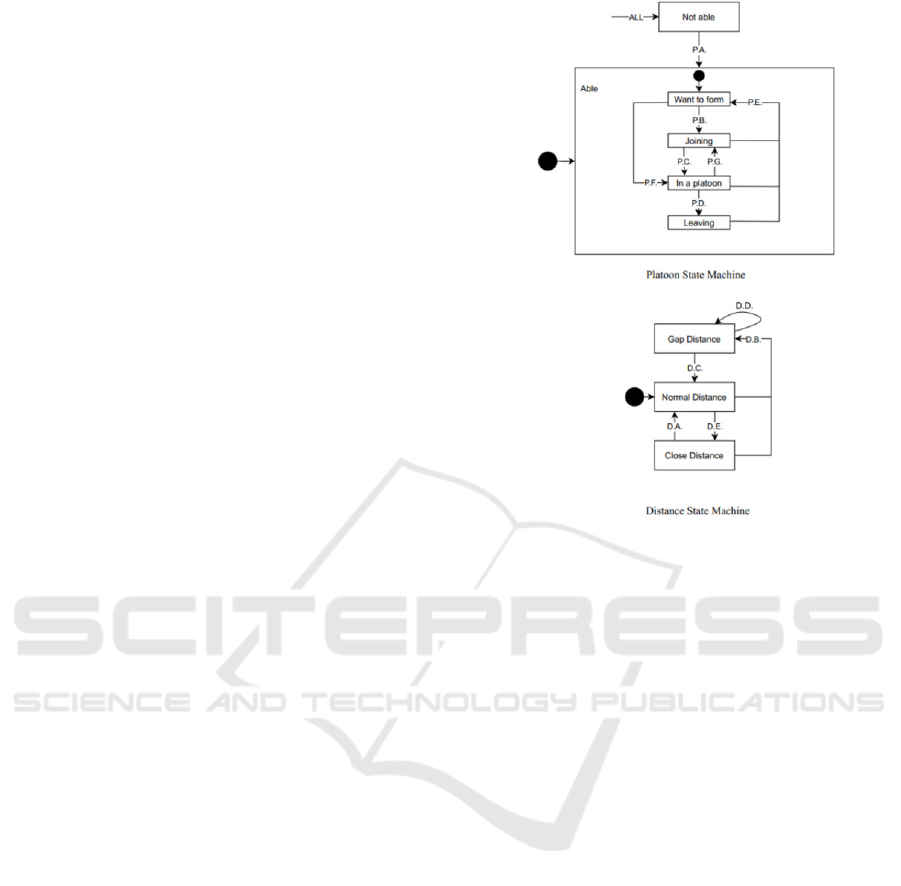
state machine. As illustrated in Figure 5, each vehicle
that can form a platoon has an implemented set of two
separate state machines that cover the multiple
potential states for platooning. The primary platoon
state machine, which displays the vehicle’s current
platooning status, serves as the foundation for all
operations. There’s also the distance state machine,
which is in charge of keeping track of the distance to
the preceding car or opening up a space, mostly to
react to a merge of other cars into the current ego lane.
Both state machines are explained briefly in the next
subsections, respectively.
The platoon state machine depicts the vehicle’s
overall condition. It specifies whether the
autonomous vehicle is now capable of driving in a
platoon or not. If the vehicle is unable to create or join
a platoon, e.g. due to a failure in the communication
module, or when the platooning mode has been
disabled by the driver, the platooning state machine
activates a transition to the state “Not able”. As a
result, while in this mode, the vehicle must maintain
a normal distance from other vehicles, therefore the
distance state machine has the state “Normal
Distance”. The state "able" is a composite state. This
is the state machine’s default initial state. It is divided
into four sub-states. “Want to form”, “Joining a
platoon”, “in a platoon” and “Leaving a platoon”.
The state "want to form" is a sub-state of the
composite state "able". This is the “able”
composite state’s initial state. The vehicle is
attempting to form a platoon in this state. It is
unrelated to any circumstance. It primarily acts as a
state indicating that the vehicle is interested in
platooning and that the system can presently form a
platoon.
Figure 5: Platoon management state machines.
The state "joining" is a sub-state of the composite
state "able". The vehicle is joining a platoon in this
state. To look at it another way, the vehicle is in this
state to achieve the desired time headway to the
preceding vehicle. In this state, the distance state
machine has a transition to “close distance” state. In
the state "in a platoon" the vehicle is acting as a full
platoon member. Besides, the vehicle is still
interested in forming a platoon if it is the last or the
first vehicle of the platoon. The distance state
machine remains in “close distance” state.
The state "leaving" indicates that the vehicle is
currently leaving the platoon. The vehicle is not
interested in forming or joining another platoon as
long as it is in this state. When a single vehicle leaves
the platoon, the condition "leaving" is reached. The
distance state machine has a transition from “close
distance” to “normal distance”.
As already mentioned, in this work no platooning
specific message is used, therefore the platooning
state of the other road user is unknown and it must be
predicted. It is though enough to know if the
preceding vehicle is “able” or “not able” to do
platooning or if it has “Want to form” or “leaving”
state. And these states can be implicitly extracted
from the MCM message.
MCM has several containers and data frames, see
(Schindler, 2019), but important for platooning use
cases are the following:
Decentralized Platoon Management and Cooperative Cruise Control of Autonomous Cars with Manoeuvre Coordination Message
285
Tolerated Distance Ahead: it is the distance to the
trajectory points that other vehicles have to respect
when they want to accept a desired trajectory of
someone else.
Tolerated Distance Behind: it is the distance to
the trajectory points that the other vehicles have to
respect when they want to accept a desired trajectory
of someone else.
Planned Trajectory: it is the future trajectory of
the vehicle.
Target Automation Level: it is the SAE level of
the automation.
Hence in the context of platooning, if a vehicle
has an automation level greater or equal to 3 and
broadcasts its current trajectory, then it has the “able”
state, otherwise it is “not able”. Though the level of
automation and current trajectory information are not
enough, they must be combined with the tolerated
distance ahead and behind to implicitly predict if the
vehicle is in the state “want to form” or “leaving”. A
vehicle which has the desire to form or join a platoon
has a relatively short tolerated distance ahead and
behind compare to the “leaving” vehicle. The exact
distance threshold can be calculated based on the
platooning desired time headway and velocity.
Although the current platoon management is
simpler compared to the MAVEN project (Schindler,
Dariani, Rondinone, & Walter, Dynamic and flexible
platooning in urban areas, March 2018) (Schindler,
Dariani, Rondinone, & Walter, Implementation and
testing of dynamic and flexible platoons in urban
areas, 2019), many transitions remain unchanged or
very similar.
Cooperative Cruise Controller
As explained, the cooperative cruise controller is a
part of the decision-making process which runs in
parallel to the trajectory planner and based on the
latest information received via V2V communication
calculates a desired velocity which must be followed
in order to maintain the desired headway with
preceding vehicle.
In this paper we present two different approaches
for the controller. The first one is a simple PD
controller (13) and the second approach is an optimal
control approach.
(
)
=
(
)
+
()
(13)
The designed PD controller is based on the gap
regulation controller for a cooperative ACC system of
Milanes et. al. (Milanes, et al., 2014). In our
approach, unlike (Milanes, et al., 2014) no leader
information is needed. Design a controller which uses
not only preceding vehicle information, but also a
leader results in string stability when the vehicles
drive with extreme short distance. Anyhow that is not
the main focus of this paper. On the other hand, in a
string of several vehicles the V2V information must
be analysed and be sorted to find out which
information belongs to the preceding and which
information belongs to the leader. And based on that
information a mapping on a HD map must be done to
calculate the net distance between ego and preceding
vehicle, as well as between ego and leader vehicle.
We believe for urban cooperation, considering the
urban environment dynamic, an extreme short
headway is not necessary, neither safe, therefore
preceding vehicle information might be enough to
design a cooperative cruise controller, but it does not
guarantee the string stability.
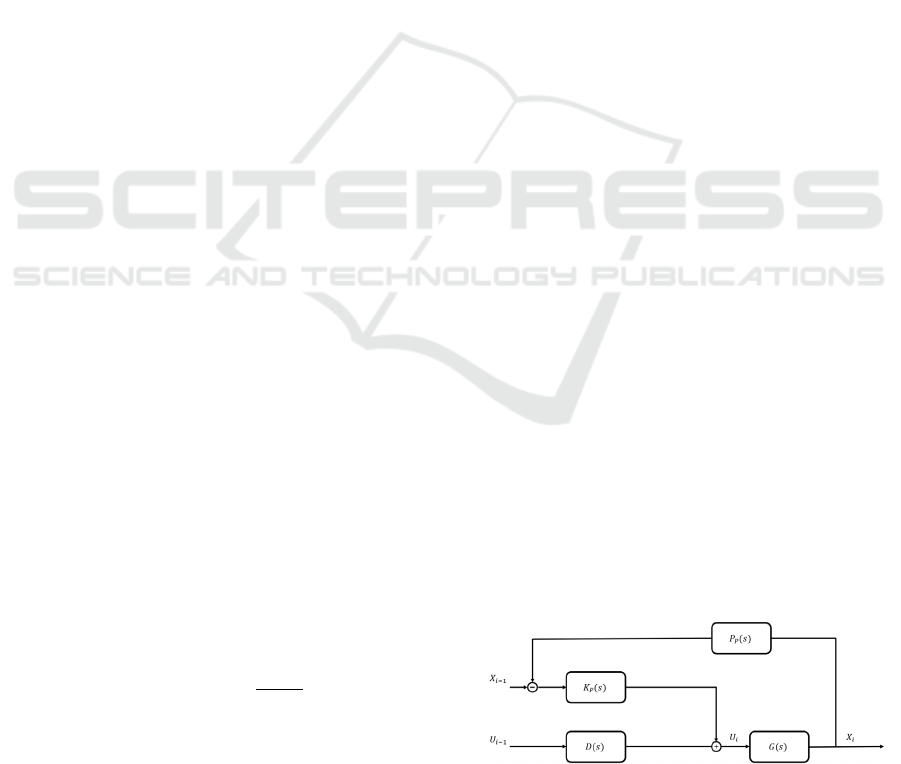
In Figure 6, () denotes the vehicle model; the
car-following policy with respect to the preceding
vehicle can be represented with terms
();
() is
the controllers that control the time-gap error with
respect to the preceding vehicle; () represents the
time delay in wireless communication;
and
are the control actions for the ego and the preceding
vehicle, respectively.
One of them is in charge of maintaining
the present speed, but instead of using the ego
vehicle’s or preceding vehicle’s speed as a feed-
forward term, the preceding vehicle’s target speed is
used. This allows for faster vehicle reaction to speed
changes and shorter transition times between throttle
and brake actuations. The other term aims to keep the
errors in the preceding
() vehicle as little as
possible.
(
)
=
+
(14)
The car-following policy can be defined as
(
)
=ℎ
(
)
+1
(15)
where ℎ
is the time-gap target value to the preceding
vehicle. The wireless communication system was
expected to have no delay for the controller design,
i.e.,
(
)
=1.
Figure 6: PD platoon controller.
VEHITS 2022 - 8th International Conference on Vehicle Technology and Intelligent Transport Systems
286
Despite the fact that the PD controllers are easy to
implement and they are effective, they do not use the
full potential of the MCM which is the use of the
current trajectory of the preceding vehicle. The PD
controller requires only the next velocity and position
of the vehicle. That is why with PD controller the
transition from “normal distance” to “close distance”
is not always smooth and comfortable, but once that
the desired headway is reached, the PD controller
functions properly. The above-mentioned problem is
due the fact that in order to reach the desired time
headway when the current time headway is bigger
than the desired, an acceleration is calculated also
when the preceding vehicle has a lower velocity or
even stand-still. To overcome this problem, a second
controller is designed for this work which uses the
complete trajectory of the preceding vehicle, included
in MCM, and calculates a velocity for the future time
horizon. The predictive nature of this controller will
avoid the above-mentioned problem.
A simple vehicle longitudinal dynamics model is
used for the optimal control with the following states;
longitudinal acceleration, longitudinal velocity,
progress which is the longitudinal position of the
vehicle and an extra state for the Lagrange term of the
objective function. The input, to be found by the
optimizer, is the desired acceleration.
represents
the engine dynamics.
=
−
=
(16)
=
As mentioned, the objective function has only
Lagrange part (17), as an extra state inside ODE of
the vehicle longitudinal dynamics model.
ℒ
,= ℒ
(
,,Δ
)
(17)
The preliminary objective is to keep the desired time
headway . At low velocities the time headway will
not guarantee a safe behaviour, that is why distance
between ego and the preceding vehicle is calculated
and the objective is to not pass the defined minimum
distance. Δ is the difference of the velocity between
the preceding vehicle and ego vehicle. This term
makes the transition from “Normal distance” to
“close distance” smooth and comfortable, especially
while joining a low speed or standing still preceding
vehicle. Boundaries can be applied to the states and
input such as defining the maximum and minimum
velocity, and acceleration. The boundaries and engine
dynamics (16) make the optimization result feasible
and customized for the vehicle dynamics.
5 TESTS AND VALIDATION
As previously mentioned, the simulation has been
done in ADORe which contains all of the necessary
data and components to create simulation scenarios
with a large number of vehicles that can interact with
one another and act like actual automobiles in diverse
urban roads. The implementation in ADORe is very
similar to the real-world implementation. All the
simulation cars are equipped with MCM senders and
receivers. Each car has also virtual sensors which are
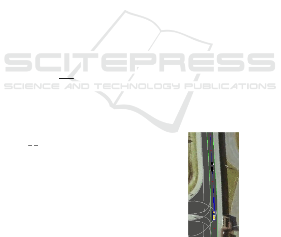
used to create an environment model. Figure 7
illustrates the simulation environment of ADORe
(Hess, et al., 2017).
Although many scenarios can be tested in
simulation, our focus is on the functionality of the
predictive controller while joining a low speed
preceding. In urban scenario, forming or joining at
intersection is common, especially when
infrastructure plays a role in traffic coordination.
Joining a low speed or stand still vehicle is probable,
but as mentioned, the PD cruise controller does not
behave smooth in this case. That is why Figure 8
illustrates the ego vehicle velocity, calculated with
predictive controller, while joining and forming a
platoon with a preceding vehicle with velocity zero
which is 100 meters ahead. The ego vehicle can have
a maximum velocity of 13.6 [/] but the vehicle
does not exceed 9[/], as the velocity is calculated
for a horizon of time and it is foreseen that a
deceleration is required. That is why the ego vehicle
decelerates smoothly till stand still.
Figure 7: An example of ADORe simulation environment.
Decentralized Platoon Management and Cooperative Cruise Control of Autonomous Cars with Manoeuvre Coordination Message
287
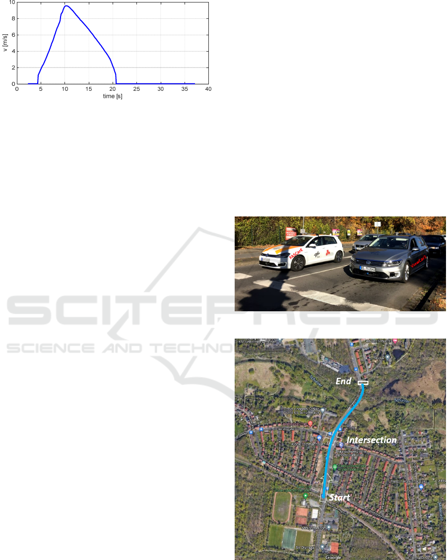
Figure 8: Velocity of the go while joining a stand still
preceding.
After several promising simulated runs the
developed prototype has been tested under real
conditions using DLR’s test vehicles on a public
urban road. In this paper the main focus is on the
urban driving scenario which was done on a street in
Braunschweig-Germany by two highly automated
vehicles of the German Aerospace Center’s Insitute
of Transportation Systems (DLR), namely FASCarE
and ViewCar 2, See Figure 9. Both cars have a similar
sensor setup. In addition, both cars are equipped with
V2X communication modules. Figure 10 illustrates
the part of the road that has been used for the real
urban scenario. As illustrated, the testing road has an
intersection and traffic light phase is communicated
via I2V communication to the vehicles. For the urban
scenario the PD controller has been used
Figure 11 illustrates the velocities of the
preceding vehicle and ego in urban environment.
Both vehicles had a safety driver on-board and at a
given moment the automation has been activated and
the data was recorded. After activation, both vehicles
are in fully autonomous mode. Some important
moments are numbered in figure 11. At “1”, the
platoon management module of the ego vehicle, the
follower, has been switched to “forming” and “close
distance”, which resulted in acceleration of the
following vehicle and closing the gap between two
vehicles. At “2” the both vehicles are “in platoon”.
While remaining in platoon, at “3” both vehicles
approaching the intersection that has a red traffic
light. Keeping the platoon stable while reducing
speed till stand still is the main reason of choosing
this road for validation. Both vehicles wait till green
traffic light and after that they accelerate and remain
in platoon till end of the track.
6 CONCLUSIONS
In this paper a decentralized approach for platoon
management and control has been presented. The
platoon management deals with platooning state of
each vehicle, and the cooperative cruise controller
calculates a velocity which must be followed in order
to be in a stable platoon. Both of these modules are a
part of decision-making module. Trajectory planner
receives the tasks from decision-making module and
plan a trajectory. The trajectory planner and decision-
making module functionalities have been approved in
simulation, using ADORe and with real urban
scenario test with two autonomous cars of German
Aerospace Center.
As next step, the predictive controller can be
tested in urban scenario and also in simulation with a
string of several vehicles.
Figure 9: DLR’s test vehicles.
Figure 10: Urban road used for validation. Braunschweig-
Germany.
VEHITS 2022 - 8th International Conference on Vehicle Technology and Intelligent Transport Systems
288
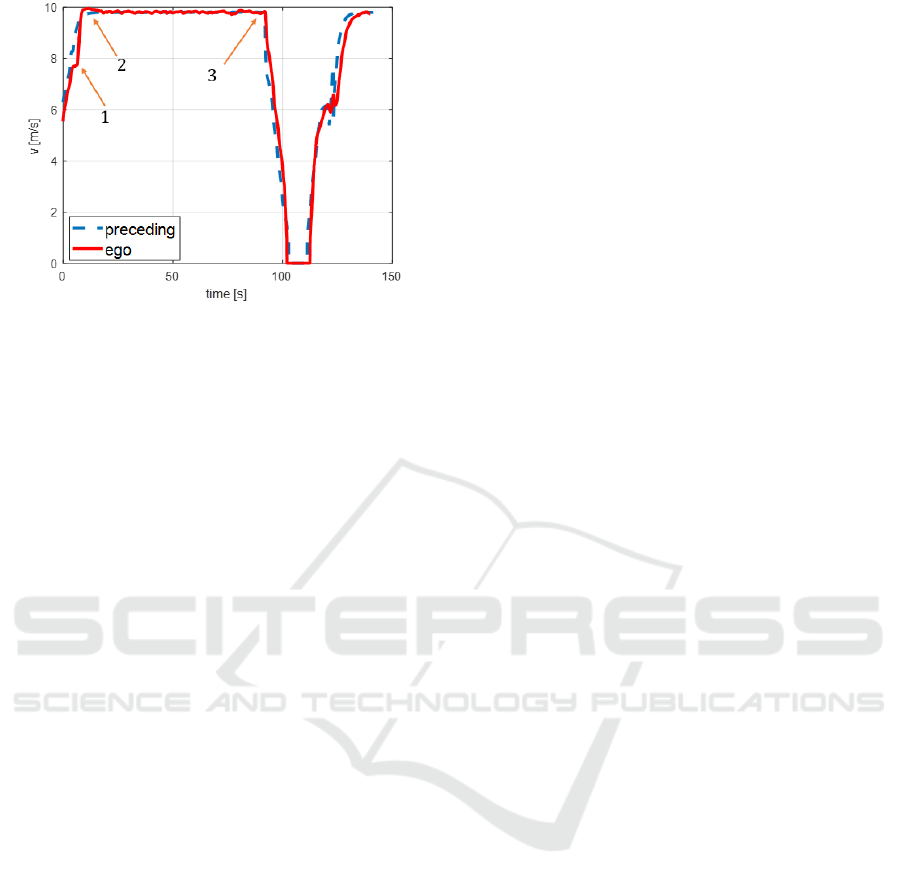
Figure 11: Velocity of the preceding and ego vehicle.
REFERENCES
Dariani, R., & Schindler, J. (2019). Cooperative Strategical
Decision and Trajectory Planning for Automated
Vehicle in Urban Areas. IEEE International
Conference on Vehicular Electronics and Safety
(ICVES).
Gerdts, M. (2003). A moving horizon technique for the
simulation of automoile test drives. Journal of applied
mathematics and mechanics.
Hess, D., Lapoehn, S., Nichting, M., Lobig, T., Behrisch,
M., Dariani, R., Schindler, J. (2017). ADORe. Von
ADORe: https://projects.eclipse.org/proposals/eclipse-
automated-driving-open-research-adore abgerufen
Lehmann, B. G., & Wolf, L. (2018). A Generic Approach
towards Maneuver Coordination for Automated
Vehicles. 21st International Conference on Intelligent
Transportation Systems (ITSC). Maui, Hawaii, USA.
McGehee, D., Mazzae, E., & Baldwin, G. (July 2000).
Driver Reaction Time in Crash Avoidance Research:
Validation of A Driving Simulation Study On A Test
Track. Proceedings of the Human Factors and
Ergonomics Society Annual Meeting.
Milanes, V., Shladover, S., Spring, J., Nowakowski, C.,
Kawayoe, H., & Nakamura, M. (2014). Cooperative
Adaptive Cruise Control in Real Traffic Situations.
IEEE Transactions On Intelligent Transportation
Systems, Vol. 15, NO. 1.
SAE International. (3. May 2021). Von
https://www.sae.org/blog/sae-j3016-update abgerufen
Schindler, J. (2019). TransAid Deliverable 7.2: System
prototype demonstration.
Schindler, J., Dariani, R., Rondinone, M., & Walter, T.
(2018). Dynamic and flexible platooning in urban areas.
AAET Braunschweig-Germany.
Schindler, J., Dariani, R., Rondinone, M., & Walter, T.
(2019). Implementation and testing of dynamic and
flexible platoons in urban areas. AAET. Braunschweig-
Germany.
Schindler, R., Blokpoe, R., Rondinone, R., Walter, T.,
Pirbyl, O., Hagen, S., Dariani, R. (2020). MAVEN
Deliverable 6.4: Integration Final Report.
Transportation, U. D. (March 2018). Critical reasons for
crashes investigated in the national motor vehicle crash
causation survey. NHTSA's National Center for
Statistics and Analysis.
Decentralized Platoon Management and Cooperative Cruise Control of Autonomous Cars with Manoeuvre Coordination Message
289
