
Battery Thermal Management Systems for EVs and Its Applications: A
Review
Haosong He
1 a
, Vishal Saini
2 b
and Xiangjie Chen
1
1
School of Mechanical, Electrical and Manufacturing Engineering, Loughborough University,
Epinal Way, Loughborough, U.K.
2
Department of Aeronautical and Automotive Engineering, Loughborough University, Loughborough, U.K.
Keywords:
Battery Thermal Management System, Electric Vehicle, Review, Lithium-ion.
Abstract:
Electric vehicles (EVs) are a viable alternatives to achieve zero greenhouse gas emission goals. However,
the prime clean power source choice- Lithium-ion battery is sensitive to temperature, thus requires a battery
thermal management system (BTMS) to secure its performance and safety. Nowadays, most commercial
EVs implement liquid BTMS because the liquids are expected to have high heat transfer efficiency with both
cooling or heating capabilities. This paper firstly reviews the adverse effects of temperature on the battery
performance from three aspects: high temperature, low temperature and temperature difference. Then three
commercialised BTMSs: air cooling BTMS, liquid cooling BTMS, and refrigerants BTMS, are introduced,
and the main advantages and disadvantages for each BTMS strategy are discussed. Finally, this paper presents
main BTMS applications the BTMS applications for EVs on market.
1 INTRODUCTION
The UK’s industrial strategy states that the transi-
tion from fossil fuel cars to zero-emission vehicles
is crucial to maintain the UK’s international compet-
itiveness in the automotive industry (Slowik et al.,
2019). EVs are regarded as a promising approach
to replace the traditional internal combustion engine
vehicles to achieve zero-emission goal (Wu et al.,
2019). Since the commercialisation of Lithium-ion
batteries by Sony in 1991, Lithium-ion batteries are
extensively used in various fields. With the rapid de-
velopment of Lithium-ion battery technologies, these
batteries are also fast becoming the optimal choice
for EVs. This is due to their outstanding strengths,
such as high-power density, long cycle life, low self-
discharge rate and no memory effect (Reddy, 2011).
The critical obstacles to date for the market penetra-
tion of EVs lies in its energy storage system. Lithium-
ion batteries’ effective capacity is strongly associated
with its discharging rate, cycle number, and tempera-
ture. Extensive studies have proved that batteries dis-
charge capacity decays with the increasing tempera-
ture, discharging currents and cycling times. The dis-
charging rate and charging cycle are associated with
a
https://orcid.org/0000-0001-9333-1068
b
https://orcid.org/0000-0002-6774-7921
EVs’ real-time working conditions and the batteries
service time. Temperature, therefore, is the only el-
ement that can be actively controlled in driving and
becomes a vital subject to be investigated.
Temperature can significantly affect battery life,
performance, safety aspects due to the inherent chem-
ical properties of Lithium-ion batteries. Batteries
can generate enormous heat during their cycling due
to the overpotential, and the resulting high tempera-
tures lead to degraded battery performance (Ma et al.,
2018). Furthermore, the low temperatures increase
the internal resistance of batteries due to the in-
creased viscosity of electrolyte that leads to the re-
duced charging and discharging capacity, resulting in
a compromised effective mileage of EVs (Wu et al.,
2019). Additionally, a low-temperature fast charge
can exacerbate Lithium dendrites formation, causing
irreversible loss of active battery materials and in-
creasing the potential of internal short circuits within
the battery. Thus, to prolong the cycle life and maxi-
mize the capability of power cells, automotive man-
ufacturers adopt battery thermal management sys-
tems(BTMSs) to actively control the operating tem-
perature range and minimize the temperature gradi-
ents inside the battery pack.
BTMS is a critical subsystem of the battery man-
agement system (BMS) aiming to maintain the sys-
He, H., Saini, V. and Chen, X.
Battery Thermal Management Systems for EVs and Its Applications: A Review.
DOI: 10.5220/0011030700003191
In Proceedings of the 8th International Conference on Vehicle Technology and Intelligent Transport Systems (VEHITS 2022), pages 57-68
ISBN: 978-989-758-573-9; ISSN: 2184-495X
Copyright
c
2022 by SCITEPRESS – Science and Technology Publications, Lda. All rights reserved
57

tem operating under an efficient and safe temperature
range. In addition, it assists cells to operate under
the same conditions, making the cell ageing uniform.
This improves EVs’ safety, driving range, lifespan,
and cost. At EV’s level, delicate mechanical integra-
tion of BTMS and battery pack is crucial to reduce the
potential abuse probabilities such as over charge, over
discharge, over heat, over cooling and increase the ro-
bustness in extreme incidents, e.g., crash situations
or cabin intrusion (Scrosati et al., 2015). At battery
and cell levels, various safety factors need to be con-
sidered in battery design and usages, such as battery
pack/cell’s voltage and current limits, temperatures,
and temperature gradients (Motors et al., 2007). The
primary task for BTMS is to maintain the temperature
in an optimal region, detect any unexpected tempera-
ture changes, prevent temperatures runaway in cells
and further propagation among cells/modules. Other
auxiliary functions include minimising the impact of
the external ambient temperature on the battery pack,
minimising the temperature differences between and
within the individual cells, and necessary humidity
control.
Numerous approaches have been developed in the
past years for thermal management of EV batteries by
considering different factors. This paper presents a
systematic review of various BTMSs for EVs, includ-
ing the adverse effects of temperature on Lithium-ion
batteries. In addition, the approaches taken up by the
EV industry, with applications to current commercial
EVs are discussed.
2 BATTERY THERMAL
MANAGEMENT SYSTEM
BTMS needs to consider the temperature influence on
battery pack level and the individual cell level.
Battery Pack Level. Non-uniform temperature
distribution within battery packs is inevitable because
the electrochemical characteristics of each cell,
including capacity, voltage and internal resistance,
cannot be identical. More importantly, the heat trans-
fer efficiency within the battery pack varies with the
cells positions and the pack layout. Fig. 1 exemplifies
that the side cells have a lower temperature compared
to the other cells in between due to more convection
heat transfer on the side (Akbarzadeh et al., 2020).
Also, the temperature on the bottom of the module is
higher than the other areas owing to the lower thermal
conductivity on the bottom interface (Akbarzadeh
et al., 2020). Temperature maldistribution at the
battery pack level, however, can be minimized with
improved BTMS design.
(a)
Temperature ℃
46.0
44.4
42.8
41.2
39.6
38.0
36.4
34.8
33.2
31.6
30.0
(b)
Figure 1: Temperature distribution on the module surface,
(a) 1C discharge and (b) 2C discharge. (Akbarzadeh et al.,
2020).
Individual Cell Level. Temperature distribution of
a single cell is also uneven since the current den-
sity is higher in electrode regions, as illustrated in
Fig. 2 (Jeon, 2014; Xu et al., 2015). However, the
temperature distribution mainly depends on the cell
shapes. The prismatic and pouch cells are expected
to have higher temperature in the tabs regions, while
the cylindrical cell is expected to have significantly
higher temperature in the core region than at its sur-
face (Inui et al., 2007; Tomaszewska et al., 2019).
The simulation results of Wang et al. (Wang et al.,
2015a) demonstrated that the prismatic cell’s surface
temperature difference could range from ∼10°C (at
2.1C) to ∼20°C (at 5C) during discharging, as illus-
trated in Fig. 3. While Fleckensteinet al.’s (Fleck-
enstein et al., 2011) study indicated that the surface
temperature distribution for the cylindrical cell was
still fairly even, but the core temperature was signifi-
cantly higher than its surface, which was ∼20°C dif-
ference at 6530 s with 70A pulse cycles, as illustrated
in Fig. 4. Admittedly, the surface temperature dis-
tribution for any shape of cells cannot be perfectly
even but enough to be neglected in low C-rate ther-
mal modelling. Jeon (Jeon, 2014) built a transient
thermo-electric model of Lithium-ion battery to pre-
dict the temperature distribution inside the cell. Fig.
5 illustrates the temperature distribution of a cylindri-
cal Lithium-ion battery at 1C discharge and charge,
respectively (Jeon, 2014). The temperature contours
presented that the maximum temperature was found
below the centre of the cell, and the minimum tem-
perature was observed at the top cap. Nevertheless,
the overall cell surface temperature difference was un-
der 3°C and the main body (except for the cap re-
gion where there is no chemical reaction happening)
surface temperature difference was under 1°C, which
was insignificant. Likewise, Xu et al.’s (Xu et al.,
2015) simulation results (see Fig. 6) indicated that
VEHITS 2022 - 8th International Conference on Vehicle Technology and Intelligent Transport Systems
58
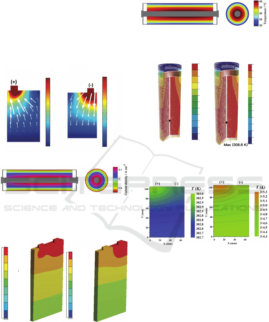
although a prismatic LiFePO
4
battery had higher tem-
perature in tab region, the maximum temperature dif-
ference were only 0.3°C and 1°C at 1C and 2C dis-
charge, receptively. Noticeably, temperatures at the
positive tab area were normally higher than those near
the negative tab due to the lower ohmic resistivity of
the copper current collector on the anode side com-
pared to aluminium on the cathode side (Xu et al.,
2015).
8.9239×10
5
×10
5
(A/m^2)
1.4
1.2
1
0.8
0.6
0.4
0.2
3997
(a)
8.9317×10
5
(A/m^2)
×10
5
2
1.8
1.6
1.4
1.2
1
0.8
0.6
0.4
0.2
4015
(b)
(c)
Figure 2: Current distribution in the prismatic cell (a) neg-
ative and (b) positive current collectors, and (c) cylindri-
cal cell during 1C discharge process (Jeon, 2014; Xu et al.,
2015).
44.151 Max ℃
41.1806
39.461
37.116
34.771
32.427
30.082
27.737
25.392
23.047 Min
(a)
77.921 Max ℃
72.04
66.159
60.278
54.397
48.516
42.634
36.753
30.872
24.991 Min
(b)
Figure 3: Maximum temperature distribution in a com-
mercial LiFePO
4
battery (capacity: 7000 mAh, size: 118
mm×63 mm×13 mm), provided by ANSYS, for 15 and 35
A discharger (Wang et al., 2015a).
Figure 4: Simulated (a) temperature distribution, (b) current
density distribution inside the LiFePO
4
cell directly at the
end of the single cell cycle (t = 6530 s).
313.2
313.0
312.7
312.5
312.3
312.1
311.8
311.6
311.4
311.2
310.9
310.7
310.5
T (K)
Max (313.2 K)
(a)
T (K)
308.6
308.5
308.3
308.2
308.0
307.9
307.7
307.6
307.4
307.3
307.1
306.0
306.8
T (K)
(b)
Figure 5: Temperature distribution of cylindrical Li-ion bat-
tery at the end of 1C (a) discharge and (b) charge (Jeon,
2014).
(a) (b)
Figure 6: Temperature distribution of a prismatic LFP cell
discharging at (a) 1C rate at 1020 s, and (b) 2C rate at 990 s
(Xu et al., 2015).
In summary, the prismatic or pouch cell is ex-
pected to have a more significant non-uniformity in
surface temperature distribution issue than the cylin-
drical cell under a high C-rate condition, while un-
der a low C-rate condition, any shapes of cells sur-
face temperature maldistribution can be reasonably
neglected. This phenomenon may raise the atten-
tion to the specific BTMS designs corresponding to
the different shapes of cells with various C-rate con-
ditions to save computational cost and design com-
plexity. To control the battery temperature from
shape and C-rate aspects, there are various thermal
mediums for different application fields, e.g., air for
heat/cooling/ventilation, liquid for cooling/heating,
Battery Thermal Management Systems for EVs and Its Applications: A Review
59

refrigerant for cooling, phase change material (PCM)
for thermal storage, heat pipe for cooling, or a com-
bination of these methods (Pesaran, 2001). To date,
air, liquid and refrigerant-based BMTS are the most
prevalent ones for the commercial EVs (Wu et al.,
2019).
2.1 Air Cooling BTMS
The air-based system is simple, reliable, economical,
and electrically safe because air is ubiquitous and has
perfect dielectric property. Thus, no isolation preven-
tions are required between coolant media and cells,
which helps air-based BTMS flexibly adapt to any
shape of commercial cells. Also, due to the absence of
liquid coolant, battery-swapping systems can be sig-
nificantly simplified. Air BTMSs utilise blowers (Fig.
7) or an air conditioning unit (Fig. 7) to actively ad-
just the battery temperature. It manages to acquire
higher efficiency than the natural one but can poten-
tially be a noise source. Besides, voluminous ducts
and blowers increase the cost, volume, and weight of
BTMS and introduce parasitic power consumption,
which acts contrary to the air-based system merits
(Basu et al., 2016). Current studies mainly focus on
the optimisations of the cell layout, airflow channel,
or combined with other cooling strategies to mitigate
the air BTMS shortfalls (Basu et al., 2016; Jang and
Rhi, 2010; Wang et al., 2015b).
Cell Layout. An appropriate cell arrangement inside
the battery pack is essential for an efficient cooling
system. Poor cell layout designs can inhibit heat dis-
sipation, induce heat accumulation inside the battery
pack during EVs operations, and cause safety haz-
ards. Various studies have been conducted on the
cell’s channels. Yang et al. (Yang et al., 2015) numer-
ically investigated the cooling performances under 2C
discharging rate with aligned arrangement (Fig. 8)
and staggered arrangement (Fig. 8) for cylindrical
cells based on a commercial FE solver at different am-
bient temperatures (at 5°C, 15°C, 25°C). They sim-
ulated various battery configurations related to the
cell’s transverse gap (S
x
) and longitudinal gap (S
y
)
and computationally derived that the aligned layout
was the optimal configuration choice for their case re-
garding the least maximum temperature, temperature
difference and total power consumption. Their results
also agreed with Fan et al.’s work (Fan et al., 2019)
that aligned arrangement had the best cooling perfor-
mance, energy effectiveness and temperature unifor-
mity. Additionally, Fan et al. proposed a new cross ar-
rangement in their studies illustrated in Fig. 8, which
had better cooling performance than the staggered one
but still less performant than the aligned arrangement,
due to the cross structures for air cooling enhanced the
local convective heat transfer, which exacerbated the
temperature differences among the cells (Fan et al.,
2019).
Airflow Channel. Channel design mainly focuses
on the inlet/outlet size, air duct angle and airflow di-
rection. Yang et al. (Yang et al., 2015) simulated
different inlet width’s influence on the cooling per-
formance, temperature uniformity, cooling efficiency
and determined that when inlet width equalled 0.5S
x
,
the system achieved the optimal performance. Com-
pared to the inlet width of 1.0S
x
, the maximum tem-
perature difference among the cells reduced 0.5°C,
and the power requirement decreased by 2.3% and
cooling efficiency increased by 1.7%. Regarding the
air duct angle optimisation, Xie et al. (Xie et al.,
2017) adjusted the inlet and outlet air duct angles to
modify the airflow inside the battery pack as illus-
trated in Fig. 9. They showed that the lowest system
temperature and temperature difference are obtained
where the inlet and outlet angle are both 2.5°. The
maximum temperature and the temperature difference
are decreased by 12.82% and 29.72%, respectively.
As for the airflow direction research, various airflow
path configurations have been proposed and can be
mainly classified into three types: U-type, Z-type, and
other novel types, see Fig. 10. U- and Z-type are the
conventional configurations. The U-type battery pack
, where the pack inlet and outlet are located at the
same side, introduces cooling air from the lower duct,
and cool air flows through the cooling channels be-
tween two adjacent battery cooling plates, and eventu-
ally, the hot air exhausts from the upper vent through
the pack outlet (Solyali and Akinlabi, 2020). Contrar-
ily, the Z-type battery pack, the inlet and the outlet are
located on the opposite sides. The outlet for conven-
tional configurations is fixed, Li et al. (Liu and Zhang,
2019) therefore proposed a novel J-type airflow con-
figuration with two outlets controlled by valves to en-
hance the cooling flexibility. The least temperature
rise and temperature differences are achieved in the
J-type configuration that the maximum temperature
difference was 3°C compared to 5°C for the conven-
tional layouts (Liu and Zhang, 2019).
In general, air BTMS offers various advantages
such as low cost, space compactness, leakage-free,
and lightweight. Whereas, the main disadvantages of
air-based BTMS are the low thermal conductivity and
heat capacity which tremendously limited its cooling
performance and can form a high-temperature gradi-
ent inside the battery pack. Also, this may impose
constraints on the assembling location of the battery
pack on EVs. Therefore, air cooling BTMS is adopted
by a few EV manufacturers nowadays.
VEHITS 2022 - 8th International Conference on Vehicle Technology and Intelligent Transport Systems
60
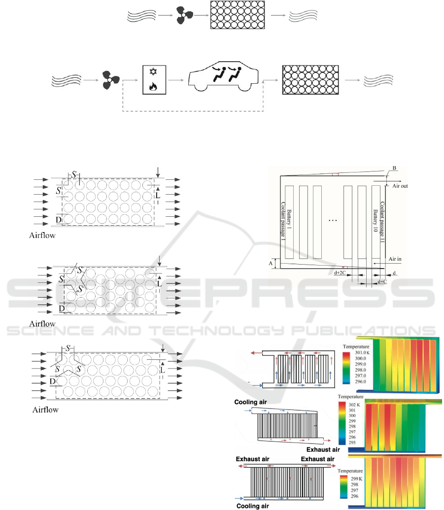
Battery packBlowerAmbient air Exhaust air
Exhaust air
(a)
Cabin Battery pack Exhaust airHVACBlowerAmbient air
Exhaust air
(b)
Figure 7: Schematic design of (a) an air-based battery cooling system using only ambient air, and (b) with preconditioned
cabin air(Scrosati et al., 2015).
(a)
(b)
(c)
Figure 8: Schematics plan view of forced air convection
system for cells arrayed in: (a) Aligned (b) Staggered (c)
Cross (Fan et al., 2019).
2.2 Liquid Cooling BTMS
Liquid cooling is the most prevalent thermal manage-
ment method on BTMS owing to its high cooling per-
formance, increased maintainability, moderate power
consumption, rapid thermal response, and suitablity
for both cooling and preheating conditions compared
to those of the air-based BTMS (Zhang et al., 2017).
Significant cooling performance and good controlla-
bility also qualify liquid-based BTMS for challenging
state-of-the-art concepts such as fast charging or ex-
Figure 9: Battery pack structure, where A is the height of
the end of the inlet, B is the height of the end of the outlet
(Xie et al., 2017).
Exhaust air
Cooling air
Figure 10: U-, Z-, and J-type BTMS and their temperature
distributions (Liu and Zhang, 2019; Solyali and Akinlabi,
2020).
treme climate conditions operations (Scrosati et al.,
2015). Consequently, the use of liquid cooling sys-
tems is a practical option for commercial BTMS ap-
plications and has already been extensively imple-
Battery Thermal Management Systems for EVs and Its Applications: A Review
61
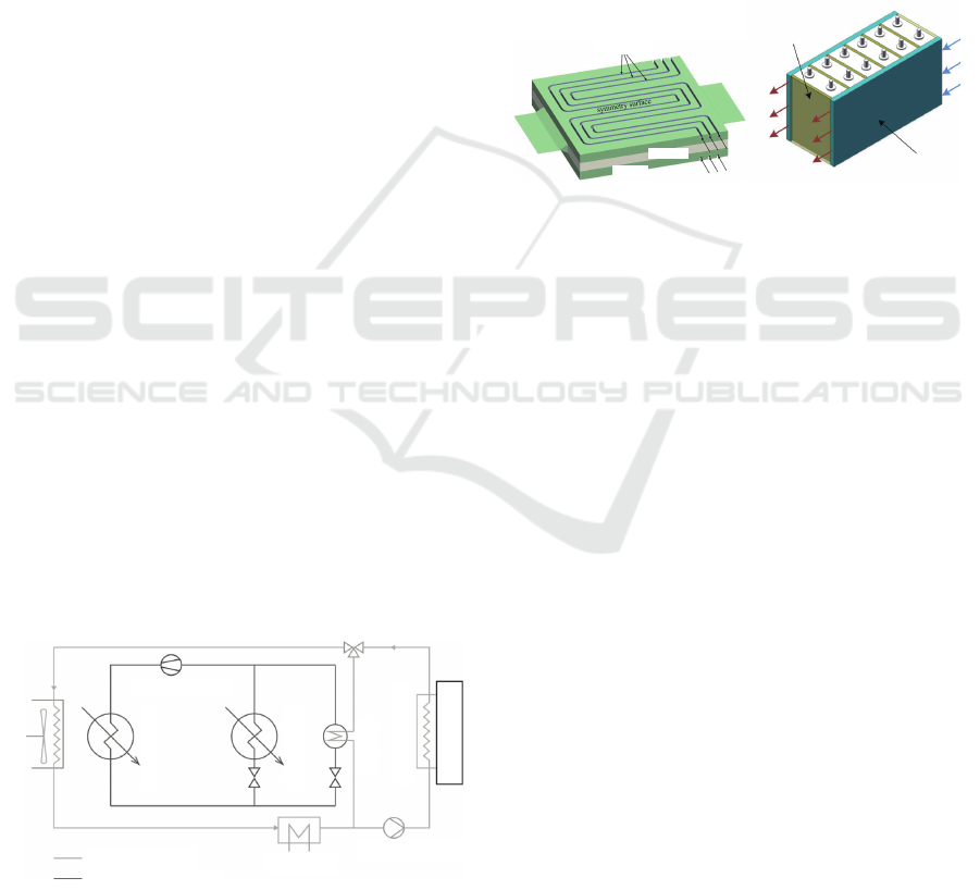
mented by automobile manufactures, including Tesla,
BMW, General Motors, BYD (Scrosati et al., 2015;
Wu et al., 2019; He et al., 2015; Thakur et al., 2020).
In liquid cooling BTMS, cells and cooling medium
are separated by the heat conducting materials. The
generated heat is conducted from the battery into the
cooling medium and removed via circulation. Thus,
strict isolation between cells and coolant is crucial
to cooling liquid since water, glycol, acetone, or re-
frigerants can be flammable, hazardous, or conduc-
tive and can cause devastating consequences such as
fire and short circuit if leakage occurs (Wang et al.,
2015b; Sund
´
en, 2019). Thus, additional channel ma-
terials and electrical insulating coatings are neces-
sary for liquid cooling BTMS. As a trade-off, the
system’s thermal resistance is elevated, and the con-
tact resistance at the contacting interfaces between
cells and conductors can inhibit the heat transfer and
form local hotspots, which weakens the thermal per-
formance of the pack accordingly (Basu et al., 2016;
Thakur et al., 2020). The typical indirect liquid-based
BTMS design for EVs tempts to a liquid and air cool-
ing combination and enable to switch between each
mode dynamically. Fig. 11 depict a schematic of a
typical indirect liquid cooling system on EV where
the air cooling is utilised under the normal opera-
tions and switching to refrigerating loop by a three-
way valve in peak loads or high ambient temperatures
circumstances to further cool down the liquid via a
chiller (Scrosati et al., 2015). The chiller shown in
Fig. 11 is a machine acting as a heat exchanger that
coupled the coolant and refrigerant circuits together
and allows the coolant to be further cooled down via
the air-conditioning system on EV. This concept has
been adopted by the Chevrolet Volt and Tesla vehi-
cles (Scrosati et al., 2015). The liquid cooling BTMS
can be classified into two types: cold plate and dis-
crete tube, according to the approaches of passing the
liquid through the channel.
Coolant circuit
Refrigerant circuit
EI. heater
Coolant pump
Cooling plate
3-way valve
Compressor
Condenser
Evaporator
Chiller
Cooler
Battery Pack
Figure 11: Dual cooling system comprising coolant and re-
frigerant circuit (Scrosati et al., 2015).
Cold Plate. The cooling plate is a flat shape metal
plate made with internal tubes where a cooling liquid
is flowing in serpentine or concentric channels, and
the heat is dissipated by convection (Wu et al., 2019).
The prismatic cell modules mostly adopt it due to its
large contact area. The typical arrangements of cold
plates include the sandwich form and the side form
that the plates are inserted between the adjacent cells
as the sandwich form or placed on the side/bottom of
the module as the side form, as illustrated in Fig. 12
(Wu et al., 2019; Sund
´
en, 2019). Cold plates present
an economical solution for liquid cooling. Neverthe-
less, the parasitic mass should also be considered in
the BTMS design.
Coolant
Battery
Jacket
(a)
Heat spreader
Cold plate
nto battery monomer (b) Between adjacent cells
(c) On module sides
(QHUJ\&RQYHUVLRQDQG0DQDJHPHQW²
(b)
Figure 12: Schematics of the cold-plate based liquid cool-
ing: (a) sandwich form (b) side form (Wu et al., 2019;
Sund
´
en, 2019).
The cold plate thermal performance has been ex-
tensively studied. Chen et al. (Chen et al., 2016) in-
vestigated the cooling performance of the sandwich
form and the side form. The temperature difference
of the sandwich form was the largest. The initial
temperature difference reached the peak value with
the increasing flow rate (approximately 7°C), and de-
creased afterwards. While the overall battery temper-
ature was continuously decreasing with the increasing
flow velocity. Chen et al. explained this was because
of the long coolant channel and high thermal conduc-
tivity of the coolant and emphasised that the low mass
flow rates in liquid cooling BTMS should be avoided.
However, higher mass flow indicates higher power
consumption. To balance the temperature difference
and the power consumption, Zhang et al. (Zhang
et al., 2017) proposed a cascade cooling method with
variable inlet coolant temperatures that utilised the
sandwich form with flat tubes assisted by the high
thermal conductivity graphite to enhance the heat
transfer, as illustrated in Fig. 13. In their cooling tests,
the initial inlet coolant temperature was identical to
the initial battery temperature and they gradually de-
creased the coolant temperature to cool down the bat-
tery. In this way, the least temperature difference (be-
low 5°C) and power consumption were obtained . The
total time to achieve a steady-state for the cascade
VEHITS 2022 - 8th International Conference on Vehicle Technology and Intelligent Transport Systems
62
cooling was approximately 2 min longer than that
of constant low-temperature coolant cooling, but the
steady-state temperatures of the two different meth-
ods were basically consistent, which is regarded as
an acceptable trade-off. Other than the side form, the
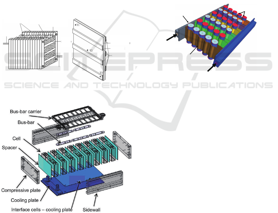
bottom form is also adopted in some studies. Smith et
al. (Smith et al., 2014) deployed a cold plate under-
neath the prismatic SANYO/PANASONIC PHEV-2,
25 Ah Lithium-ion cells, as illustrated in Fig. 14. In
their study, Smith et al. treated the cells as a spa-
tially uniform heat source. This is supported by the
fact that the PHEV2 cell has a thick case leading to
the lower conduction rate, and the temperature gradi-
ents are therefore not noticeable. However, it is still
worth emphasising that the bottom cooling configura-
tion may not be the most effective approach to dissi-
pate the heat because, in real situations, the cell’s lo-
cal temperature around tabs is hotter than the bottom
area due to the higher current density there (Sund
´
en,
2019).
End plate
Outlet
Cell
Flexible
graphite
Flexible
graphite
Cell
Flat tube
bank
Flat
tube
Inlet
Figure 13: Designed battery pack and layout of the temper-
ature measured points (Zhang et al., 2017).
Figure 14: The layout of a battery module for SANYO pris-
matic cells. (Smith et al., 2014).
The previous methods are all based on prismatic
cells. Basu et al. (Basu et al., 2016) designed a novel
side form BTMS for cylindrical cells to investigate
the applicability of cold pate cooling for cylindrical
cells. The Li-NCA/C 18650 cells were wrapped by
the aluminium conduction elements and the heat
from cells was conducted to the side aluminium
channels carrying coolant liquid, as illustrated in Fig.
15. This structure also achieves leak-proof design
because of separation of conduction element owing
to the conduction elements separate the coolant and
cells. In respect to the thermal performance, the cell’s
temperature could be maintained under 27°C (at 0.9C
discharging rate), 28°C (at 1.8C discharging rate),
30°C (at 2.7C discharging rate) when the coolant inlet
temperature was 23°C and flow velocity was 0.2 m/s.
It revealed the excellent thermal performance of the
proposed BTMS. Nevertheless, the thermal contact
resistances at the conduction elements and cells
interfaces were found to be the biggest hindrance to
such BTMS configuration.
Channel
Conducon Element
18650 cells
Coolant flow
Coolant flow
Channel
Cells
Coolant flow
Conduction element
Coolant flow
Figure 15: Geometry of the pack and the BTMS for the
cylindrical cells based battery pack (Basu et al., 2016).
Discrete Tube. Discrete tubes are more applicable
for cylindrical batteries due to their more flexible
shape compared to the cold plate. A representative
of discrete tube design is from Tesla, Inc where they
adopted ribbon-shaped tubes with a wave profile on
their Model S EV. Fig. 16 is a top-down view of a por-
tion of a cooling tube with a wavy or scalloped profile
(Tennessen et al., 2014). The illustrated shape of the
cooling tube serves several purposes. First, it allows
a larger area portion of each cell to be in thermal con-
tact with the cooling tubes, thereby improving heat
transfer. Second, it can achieve higher packing den-
sity of cylindrical cells battery pack by minimising the
separation distance between adjacent cell rows. The
overall discrete tube layout of the Tesla Model S is
depicted in Fig. 17 (R. Maughan, 2021).
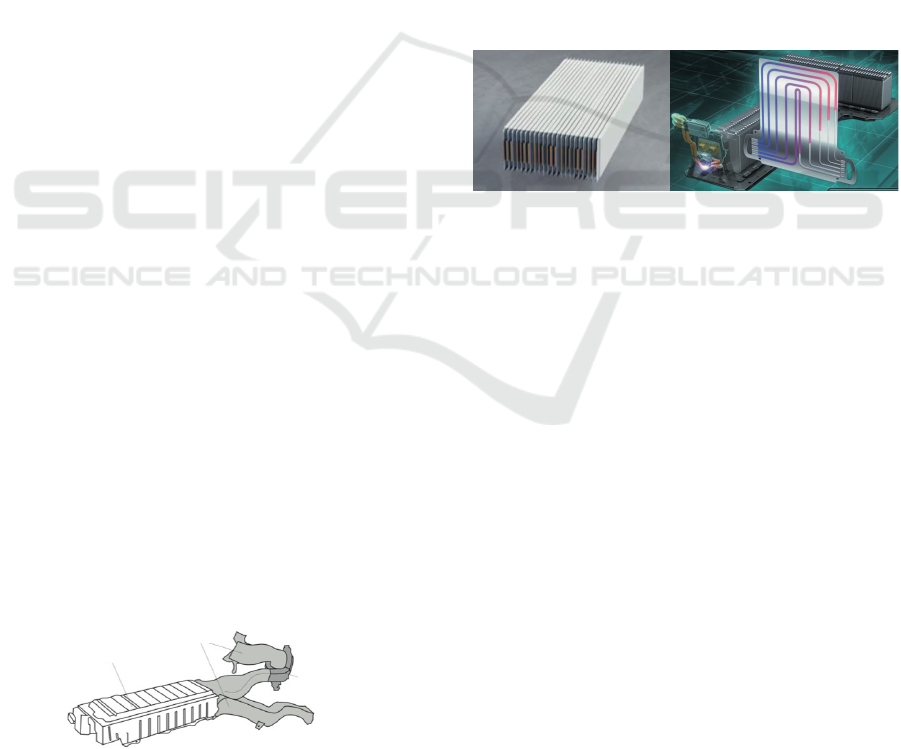
2.3 Refrigerant BTMS
A typical liquid cooling BTMS configuration is illus-
trated in Fig. 11, which contains two circulations -
the coolant circulation and the refrigerant circulation
Battery Thermal Management Systems for EVs and Its Applications: A Review
63
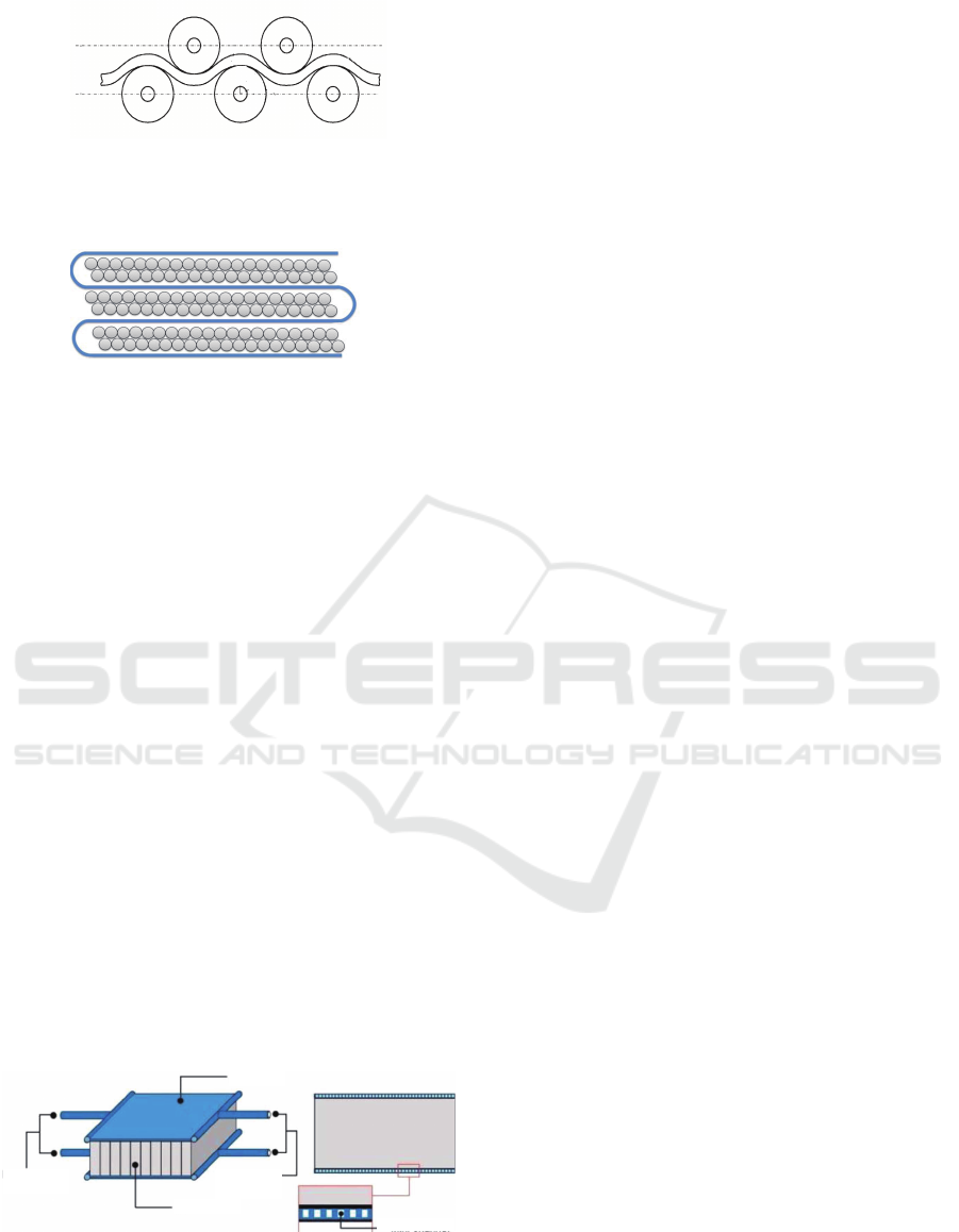
Figure 16: A top-down view of a portion of a cooling
tube inserted between a plurality of cells (Tennessen et al.,
2014).
Water glycol inlet
Water glycol outlet
Figure 17: The schematic of Tesla Model S discrete tube
cooling: tube is lagged with high heat transfer material and
in close contact with side of cells (R. Maughan, 2021).
coupled by a chiller. Such design adds weight and
complexity to the system. Thus, refrigerant BTMS
has been proposed to overcome the disadvantage of
the dual-circuit model. In refrigerant BTMS, the bat-
tery cooling circuit is directly integrated into the ex-
isting refrigerant cycle on EV. Therefore, the chiller
and coolant exchange circuits can be entirely removed
from the refrigerant system, which more weight and is
more compact than the liquid-based BTMS (Scrosati
et al., 2015). Also, the refrigerant has a lower elec-
trical conductivity which reduces the possibility of a
short circuit (Bhattacharjee et al., 2020). In practical
applications, the configurations of refrigerant cooling
BTMS resemble the cold plates liquid cooling in the
way that heat sinks with embedded microchannels are
installed on the top and bottom sides of the module
(see Fig. 18 ) and absorb the heat from the mod-
ules. On the down side, the refrigerant BTMS cannot
perform the heating of the battery, as may be needed
in cold environments. This is because the refrigerant
cannot be heated. Thus, refrigerant BTMS will not
be able to preheat the battery in a cold environment
(Lu et al., 2020) and common solution is applying an
extra electric heater to the battery (Roth et al., 2004).
Refrigerant
inlet
Refrigerant
outlet
Cell
Heat sink
Mini-channel
Figure 18: Diagram of refrigerant BTMS in practical appli-
cations form (Katoch and Eswaramoorthy, 2020; Lu et al.,
2020).
The merit of the refrigerant cooling lies in that
the refrigerant directly flows into the battery modules
without a secondary heat transfer assisted by a chiller.
Therefore, the refrigerant BTMS has a higher evap-
oration heat transfer coefficient, heat transfer effec-
tiveness and simplicity compared to the liquid cool-
ing BTMS. Hong et al. (Hong et al., 2020) experi-
mentally investigated the thermal performance of di-
rect two-phase refrigerant cooling. Due to its com-
pact structure with mini channels, the weight of the
cooling module was approximately 56% lower than
that of the liquid cooling. They adopted R134a re-
frigerant as the cooling fluid compared to the ethy-
lene glycol/water mixture (50:50) - a popular liquid
coolant choice for EV manufacturers. Their results
indicated that the maximum temperature of two-phase
refrigerant cooling was 41.1°C under 2C fast charg-
ing conditions while that of the liquid cooling was
49.1°C, exceeding the cell’s allowed operational tem-
perature. During the regular charging and US06 drive
cycle tests, although refrigerant and liquid cooling
maintained the maximum temperature under 30°C,
the overall maximum temperature of refrigerant cool-
ing was consistently lower than that of liquid cooling
during the whole process. As for the temperature dif-
ference, both cooling methods maintained the max-
imum temperature gradients below 5°C under 0.5C-
2C charging rates conditions when liquid coolant tem-
perature was 25°C, and the refrigerant vapour quality
(χ = mass
vapour
/mass
total
) was 0.85, respectively.
It should emphasise that R134a, as the most pop-
ular refrigerant, has been banned by the European
Union for its usage on new cars after 2022. Due
to R134a belongs to fluorinated greenhouse gas with
high global warming potential (GWP), GWP=1410
(Schwarz et al., 2011). Hong et al. (Hong et al.,
2020) proposed R1234yf (GWP= 4) as an alternative
to R134a, but R1234yf is highly flammable. The fu-
ture developments point toward making the liquid car-
bon dioxide - R744 (GWP=1, non-ozone depleting,
non-toxic, non-flammable) the standard (Hoffmann,
2017).
3 BTMS APPLICATIONS ON EVs
The growth of EVs has soared over the last five years
(IEA, 2021). The representative newer manufactur-
ers include fast-growing companies e.g., Tesla, NIO,
and the established automakers e.g., BMW, Nissan,
GM, Renault There were about 7.2 million electric
cars on the world’s roads by 2019, among which
the HEV(hybrid EV) and PHEV(plug-in hybrid EV)
dominated in the early 2010, while BEV (battery EV)
VEHITS 2022 - 8th International Conference on Vehicle Technology and Intelligent Transport Systems
64
started to take over the market after 2015 (IEA, 2021).
According to The Global EV Outlook Report (IEA,
2021), BEV is expected to reach an average driving
range of 350-400 km corresponding to battery sizes
of 70-80 kWh by 2030, which offers similar ranges to
an average fuel car (Wallbox, 2021). Therefore, EV
manufacturers are pursuing for higher specific energy
and specific power batteries to complete the full trans-
action from PHEV/HEV to BEV and be more com-
petitive against the fuel vehicles. In 2019, Chevro-
let halted production of PHEV - Chevrolet Volt se-
ries and replaced with a new BEV series - Chevrolet
Bolt (Jordan Fromholz, 2021). In June 2021, Model
S, as Tesla’s flagship originally launched in 2012, and
equipped with a 100 kWh battery powertrain and the
maximum driving range reached 637 km under WLTP
test (Electric Vehicle Database, 2021; Mock et al.,
2014). In January of the same year, NIO announced
their first saloon - ET7, which equipped with an even
larger 150 kWh solid-state battery and estimated driv-
ing range reached 1000 km under NEDC test (Mock
et al., 2014; NIO, 2021). Due to the increased battery
capacity and battery generated heat in driving surges,
more efficient and powerful BTMS are required to se-
cure EVs safety and performance. Table 1 summaries
the main commercial EVs on the market to date and
introduced their BTMSs, specifications and perfor-
mance. It indicates that due to the increased battery
capacity, the driving range of newer BEVs has be-
come similar to fossil fuel vehicles. Meanwhile, the
mainstream BTMS methods for EVs are still limited
to air, liquid, and refrigerant based BTMSs, where liq-
uid BTMS is the optimum choice for most EV manu-
facturers to date.
Air BTMS. Due to the simplicity of air cooling
BTMS, forced convection air cooling has been pre-
sented in commercial EVs at the earliest stage. The
earliest hybrid EVs (HEVs), such as Honda Insight
and Toyota Prius (Fig. 19), are the early examples
adopting the air cooling approach and proved the fea-
sibility of air cooling BTMS (Zolot et al., 2001; Zolot
et al., 2002; Scrosati et al., 2015). More recently, a
representative BEV - Renault Zoe 2019 adopted an
air conditioning unit system to blow cool air over the
battery (G
´
eraldine Dao, 2019).
Battery pack
Ducts
Blower/fan
Figure 19: Toyota Prius Battery Pack including air ducts
(Roth et al., 2004).
Liquid BTMS. As the most prevalent cooling
method, liquid BTMS has been adopted by various
automobile manufactures. Tesla’s BTMS implements
liquid glycol as a coolant distributed throughout the
battery pack to transfer heat to the refrigeration cycle
and utilises electric resistance heating in cold weather.
GM adopts prismatic cells instead named Ultium bat-
teries that flat cell pouches can stack on top of each
other to save more space, illustrated in Fig.20 and
cooled with aluminium cooling plates with embedded
mini channels filled with liquid glycol (R. Maughan,
2021; George Bower, 2015; GM, 2020a). Such mod-
ular design offers a significant flexible energy com-
binations availability that can range from 50 kWh to
over 200 kWh. Thus, engineers can customize various
battery capacities for different EV models. Addition-
ally, the mini-channel cooling approach can minimize
the installation limitations compared to air cooling
BTMS, which can translate to more miles on a single
charge with less volume (GM, 2020a; GM, 2020b).
Figure 20: GM’s new automotive battery packs consist
of flat stackable Ultium cells with an aluminium cooling
plate sandwiched between them (George Bower, 2015; GM,
2020a).
Refrigerant BTMS. It has been adopted in some
EV models. BMW is the representative manufacture
in favour of the refrigerant cooling method. BMW
i3, as a lightweight EV, adopted a 42.2kWh battery,
and driving range reached 246 km (Boretti, 2020).
BMW i3 contains much less fluid compared to Tesla
Model 3 since it adopts the refrigerants from the air
conditioning system and only requires a small upsiz-
ing of the air conditioning compressor to compen-
sate for increased refrigerant demand (Munro, 2020).
Thus, the weight of the cooling system only com-
poses about 3% of the total battery weight (Schoewel
and Hochgeiger, 2014). Regarding the thermal per-
formance, the BMW i3 utilises a bottom cooling plate
in its battery, elucidated in Fig. 21, which have only
module-level contact to the coolant system. There-
fore, temperature control performance can be less ef-
ficient than the Tesla Models, whereas the assembly
and maintenance complexity has been significantly
decreased (Munro, 2020; Schoewel and Hochgeiger,
2014).
Battery Thermal Management Systems for EVs and Its Applications: A Review
65
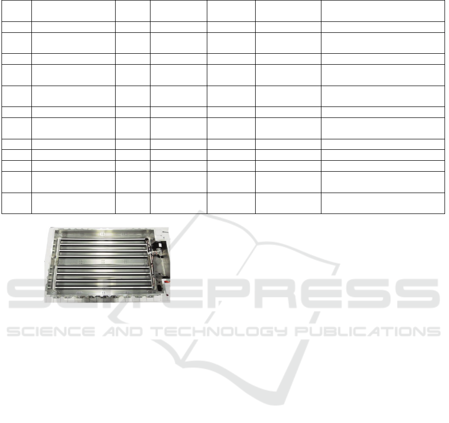
Table 1: BTMS Strategies of Commercial Vehicles.
Year Model Type BTMS Capacity
(kWh)
Battery Range
(km)
Reference
2015 BMW i8 PHEV Refrigerant 7.1-11.6 37 (Loveday, 2014)
2019 Renault Zoe BEV Forced Air 52 394 (Delobel et al., 2017;
G
´
eraldine Dao, 2019)
2019 Chevrolet Volt PHEV Cold Plate 18.4 85 (Loveday, 2020; GM, 2011)
2019 Kia Niro BEV Liquid 64 385 (Halvorson, 2019; Kane,
2019; Nisewanger, 2019)
2019 MINI SE BEV Liquid 32.6 225 -233 (Boeriu, 2020; Mini, 2021;
Moloughney, 2020)
2020 Porsche Taycan BEV Liquid 79-93 408-484 (Auto Express, 2021)
2020 Hyundai Kona BEV Cold Plate 64 482 (Nisewanger, 2018; Hyundai,
2011)
2020 Hyundai IONIQ BEV Fan 38 310 (Hyundai, 2021)
2020 Volkswagen ID.3 BEV Cold Plate 45-77 349-540 (Volkswagen, 2020)
2021 BMW i3 BEV Refrigerant 37.9 292-305 (BMW, 2021; Munro, 2020)
2021 Tesla Model S BEV Discrete
Tube
100 637-652 (Electric Vehicle Database,
2021; Tesla, 2021b)
2021 Tesla Model 3 BEV Discrete
Tube
54 - 82 447-579 (Tesla, 2021a)
Figure 21: BMW i3 bottom refrigerant cooling plate layout
(Munro, 2020).
4 CONCLUSIONS
Nowadays, the use of Lithium-ion batteries in EVs
tends to have higher energy density, power and
more compact design, which requires more advanced
BTMSs to enhance the prospects of safety, reliability
and performance. This paper extensively reviews and
classifies the current commercial BTMS on EVs ac-
cording to its cooling medium. Air cooling, as the ear-
liest BTMS on EVs, has the advantages of low weight,
low cost and easy maintenance, but low cooling per-
formance is the main bottleneck limiting its utilisa-
tion on the current EVs. The common trend in the
past years has been to move from air BTMS to liquid
BTMS to gain a more powerful cooling ability and in-
crease the vehicle range accordingly. Liquid cooling
BTMS is the most prevalent cooling method to EV
manufacturers to date and also expected to dominant
the EV market in the future. Whereas, the leakage,
increment of parasitic mass, and higher design com-
plexity and price are the main disadvantages of liq-
uid BTMS. The refrigerant BTMS therefore becomes
an option to some EV manufactures as it has lower
design complexity, weight, and cost, but the cooling
performance is less efficient than the liquid BTMS
and needs an extra heating system to heat up batter-
ies. Currently, it is a popular solution to the low cost
EVs. For the future BTMS design, the light weight,
low cooling power consumption, and higher thermal
conductivity BTMS integrating with multiple cool-
ing methods will be a possible solution to the current
facing limitations. Moreover, advanced but currently
with low techonology readiness levels BTMSs such
as heat pipe, phase change materials, and thermoelec-
tric can also potentially be the future solutions to EVs,
but this is beyond the scope of this work.
REFERENCES
Akbarzadeh, M., Kalogiannis, T., Jaguemont, J., He, J., Jin,
L., Berecibar, M., and Van Mierlo, J. (2020). Ther-
mal modeling of a high-energy prismatic lithium-ion
battery cell and module based on a new thermal char-
acterization methodology. Journal of Energy Storage,
32:101707.
Auto Express (2021). Porsche taycan review -
range, charging and running costs. https://
www.autoexpress.co.uk/porsche/taycan/range.
Basu, S., Hariharan, K. S., Kolake, S. M., Song, T., Sohn,
D. K., and Yeo, T. (2016). Coupled electrochemical
thermal modelling of a novel li-ion battery pack ther-
mal management system. Applied Energy, 181:1–13.
Bhattacharjee, A., Mohanty, R. K., and Ghosh, A. (2020).
Design of an optimized thermal management system
for li-ion batteries under different discharging condi-
tions. Energies, 13(21).
VEHITS 2022 - 8th International Conference on Vehicle Technology and Intelligent Transport Systems
66

BMW (2021). Technical data of the bmw i3.
https://www.bmw.co.uk/en/all-models/bmw-i/i3/
2020/technical-data.BMW--i3-120Ah.html.
Boeriu (2020). Mini cooper se – technical details and spec-
ifications. https://www.bmwblog.com/2020/01/18/
mini-cooper-se-technical-details-and-specifications/.
Boretti, A. (2020). On-board electric vehicles electricity
production by high-efficiency internal combustion en-
gines. Przegad Elektrotechniczny, 96.
Chen, D., Jiang, J., Kim, G. H., Yang, C., and Pesaran, A.
(2016). Comparison of different cooling methods for
lithium ion battery cells. Applied Thermal Engineer-
ing, 94.
Delobel, B., Gordon, I. J., and Leveau, L. (2017). Zoe bat-
tery durability, field experience and future vision. Re-
nault Battery Development Department.
Electric Vehicle Database (2021). Model s long
rnage. https://ev-database.uk/car/1404/Tesla-Model-
S-Long-Range.
Fan, Y., Bao, Y., Ling, C., Chu, Y., Tan, X., and Yang, S.
(2019). Experimental study on the thermal manage-
ment performance of air cooling for high energy den-
sity cylindrical lithium-ion batteries. Applied Thermal
Engineering.
Fleckenstein, M., Bohlen, O., Roscher, M. A., and B
¨
aker,
B. (2011). Current density and state of charge inho-
mogeneities in li-ion battery cells with lifepo4 as cath-
ode material due to temperature gradients. Journal of
Power Sources, 196(10):4769–4778.
George Bower (2015). Tesla or gm: Who
has the best battery thermal management?
https://insideevs.com/photo/3957897/tesla-or-gm-
who-has-the-best-battery-thermal-management/.
GM (2011). Cooling fins help keep chevrolet volt battery
at ideal temperature. https://media.gm.com/media/us/
en/gm/home.detail.html/content/Pages/news/us/en/
2011/Feb/0214 battery.html.
GM (2020a). Flat, stackable ev batteries are the
winning formula. https://www.gm.com/our-stories/
technology/flat-battery-stackable-ev.html.
GM (2020b). Gm reveals all-new flexible platform and
ultium batteries. https://www.gm.com/our-stories/
commitment/ev-battery-modular-technology.html.
G
´
eraldine Dao (2019). Pre-conditioning
and your electric car’s range.
https://easyelectriclife.groupe.renault.com/en/day-to-
day/range/pre-conditioning-and-your-electric-cars-
range/.
Halvorson (2019). 2019 kia niro ev: first drive of 239-mile
electric crossover. https://www.greencarreports.com/
news/1121294 2019-kia-niro-ev-first-drive-of-239-
mile-electric-crossover.
He, W., Zhang, G., Zhang, X., Ji, J., Li, G., and Zhao,
X. (2015). Recent development and application of
thermoelectric generator and cooler. Applied Energy,
143:1–25.
Hoffmann, G. (2017). Refrigerants for mobile air condi-
tioning. ATZ worldwide, 119(1):16–21.
Hong, S. H., Jang, D. S., Park, S., Yun, S., and Kim, Y.
(2020). Thermal performance of direct two-phase re-
frigerant cooling for lithium-ion batteries in electric
vehicles. Applied Thermal Engineering, 173:115213.
Hyundai (2011). New kona electric. https://
www.hyundai.co.uk/new-cars/kona-electric.
Hyundai (2021). Ioniq electric, pure electric, pure satis-
faction. https://www.hyundai.co.uk/new-cars/ioniq/
electric.
IEA (2021). Global electric car stock, 2010-2019, iea, paris.
https://www.iea.org/data-and-statistics/charts/global-
electric-car-stock-2010-2019.
Inui, Y., Kobayashi, Y., Watanabe, Y., Watase, Y., and Ki-
tamura, Y. (2007). Simulation of temperature distri-
bution in cylindrical and prismatic lithium ion sec-
ondary batteries. Energy Conversion and Manage-
ment, 48(7):2103–2109.
Jang, J.-C. and Rhi, S.-H. (2010). Battery thermal man-
agement system of future electric vehicles with loop
thermosyphon.
Jeon, D. H. (2014). Numerical modeling of lithium ion bat-
tery for predicting thermal behavior in a cylindrical
cell. Current Applied Physics, 14(2):196–205.
Jordan Fromholz (2021). The chevy volt vs. bolt: The dif-
ferences. The Chevy Volt vs. Bolt: The Differences.
Kane (2019). Everything we know about the 2019 kia niro
ev (e-niro). https://insideevs.com/news/345556/2019-
kia-niro-ev-e-niro/.
Katoch, S. S. and Eswaramoorthy, M. (2020). A detailed
review on electric vehicles battery thermal manage-
ment system. In IOP Conference Series: Materials
Science and Engineering, volume 912, page 042005.
IOP Publishing.
Liu, Y. and Zhang, J. (2019). Design a j-type air-based bat-
tery thermal management system through surrogate-
based optimization. Applied Energy, 252.
Loveday (2014). First bmw i8 deliveries scheduled for
june - final performance / fuel consumption fig-
ures released. https://insideevs.com/news/320920/
first-bmw-i8-deliveries-scheduled-for-june-final-
performance-fuel-consumption-figures-released/.
Loveday (2020). 2016-2019 chevy volt review from honest
owner’s perspective. https://insideevs.com/reviews/
408403/2016-2019-chevrolet-volt-review/.
Lu, M., Zhang, X., Ji, J., Xu, X., and Zhang, Y. (2020).
Research progress on power battery cooling technol-
ogy for electric vehicles. Journal of Energy Storage,
27(Feb.):101155.1–101155.16.
Ma, S., Jiang, M., Tao, P., Song, C., Wu, J., Wang, J.,
Deng, T., and Shang, W. (2018). Temperature effect
and thermal impact in lithium-ion batteries: A review.
Progress in Natural Science: Materials International,
28(6):653–666.
Mini (2021). New mini electric. https://www.mini.co.uk/
en
GB/home/range/mini-electric.html.
Mock, P., K
¨
uhlwein, J., Tietge, U., Franco, V., Bandi-
vadekar, A., and German, J. (2014). The wltp: How a
new test procedure for cars will affect fuel consump-
tion values in the eu. International council on clean
transportation, 9(3547).
Moloughney (2020). 2020 mini cooper se: Big
fun, short on range, but easy on the wal-
Battery Thermal Management Systems for EVs and Its Applications: A Review
67

let. https://insideevs.com/reviews/395747/2020-mini-
cooper-se-first-drive-report/.
Motors, T., Berdichevsky, G., Kelty, K., Straubel, J., and
Toomre, E. (2007). The tesla roadster battery system.
tesla motors inc.
Munro (2020). Tearing down tesla segment 4: Battery
cooling system comparison on tesla model 3 vs.
bmw i3. https://leandesign.com/tearing-down-tesla-
segment-4-battery-cooling-system-comparison-on-
tesla-model-3-vs-bmw-i3/.
NIO (2021). Nio et7-ready for tomorrow-et7. https://
www.nio.com/et7.
Nisewanger (2018). Exclusive: details on hyundai’s
new battery thermal management design. https:
//electricrevs.com/2018/12/20/exclusive-details-on-
hyundais-new-battery-thermal-management-design/.
Nisewanger (2019). Lg sues sk, alleges stolen trade
secrets used to make kia niro and future vw batter-
ies. https://electricrevs.com/2019/04/30/lg-sues-sk-
alleges-stolen-trade-secrets-used-to-make-kia-niro-
and-future-vw-batteries/.
Pesaran, A. A. (2001). Battery thermal management in
ev and hevs: issues and solutions. Battery Man,
43(5):34–49.
R. Maughan (2021). What is the best electric vehicle battery
cooling system? https://avidtp.com/what-is-the-best-
cooling-system-for-electric-vehicle-battery-packs/.
Reddy, T. B. (2011). Linden’s handbook of batteries.
McGraw-Hill Education.
Roth, E. P., Crafts, C. C., Doughty, D. H., and McBreen, J.
(2004). Advanced technology development program
for lithium-ion batteries: thermal abuse performance
of 18650 li-ion cells. Sandia Nat. Lab., Albuquerque,
NM, USA, Rep. SAND2004-0584.
Schoewel, F. and Hochgeiger, E. (2014). The high-voltage
batteries of the bmw i3 and bmw i8. In Proceed-
ings of the Advanced Automotive Battery Conference
(AABC), Atlanta, GA, USA, volume 45.
Schwarz, W., Gschrey, B., Leisewitz, A., Herold, A., Gores,
S., Papst, I., Usinger, J., Oppelt, D., Croiset, I., Peder-
sen, P. H., et al. (2011). Preparatory study for a review
of regulation (ec) no 842/2006 on certain fluorinated
greenhouse gases. Final report, Sept.
Scrosati, B., Garche, J., and Tillmetz, W. (2015). Advances
in battery technologies for electric vehicles. Wood-
head Publishing.
Slowik, P., Hall, D., Lutsey, N., Nicholas, M., and Wappel-
horst, S. (2019). Funding the transition to all zero-
emission vehicles. White Paper.
Smith, J., Hinterberger, M., Hable, P., and Koehler, J.
(2014). Simulative method for determining the op-
timal operating conditions for a cooling plate for
lithium-ion battery cell modules. Journal of Power
Sources, 267:784–792.
Solyali, D. and Akinlabi, A. (2020). Configuration, de-
sign, and optimization of air-cooled battery ther-
mal management system for electric vehicles: A re-
view. Renewable and Sustainable Energy Reviews,
125(109815).
Sund
´
en, B. (2019). Hydrogen, Batteries and Fuel Cells.
Academic Press.
Tennessen, P. T., Weintraub, J. C., and Hermann, W. A.
(2014). Extruded and ribbed thermal interface for use
with a battery cooling system. US Patent 8,758,924.
Tesla (2021a). Model 3. https://www.tesla.com/en gb/
model3?redirect=no.
Tesla (2021b). Model s plain. https://ev-database.uk/car/
1405/Tesla-Model-S-Plaid.
Thakur, A. K., Prabakaran, R., Elkadeem, M., Sharshir,
S. W., Arıcı, M., Wang, C., Zhao, W., Hwang, J.-Y.,
and Saidur, R. (2020). A state of art review and future
viewpoint on advance cooling techniques for lithium–
ion battery system of electric vehicles. Journal of En-
ergy Storage, 32:101771.
Tomaszewska, A., Chu, Z., Feng, X., O’Kane, S., Liu, X.,
Chen, J., Ji, C., Endler, E., Li, R., Liu, L., et al. (2019).
Lithium-ion battery fast charging: A review. ETrans-
portation, 1:100011.
Volkswagen (2020). Battery and charging options.
https://www.volkswagen-newsroom.com/en/the-
new-id3-6240/battery-and-charging-options-6247.
Wallbox (2021). How do evs compare to gas cars?
https://blog.wallbox.com/how-do-evs-compare-to-
gas-cars/.
Wang, C., Lin, T., Huang, J., and Rao, Z. (2015a). Tempera-
ture response of a high power lithium-ion battery sub-
jected to high current discharge. Materials Research
Innovations, 19(sup2):S2–156.
Wang, Q., Jiang, B., Xue, Q. F., Sun, H. L., Li, B., Zou,
H. M., and Yan, Y. Y. (2015b). Experimental investi-
gation on ev battery cooling and heating by heat pipes.
Applied Thermal Engineering, pages 54–60.
Wu, W., Wang, S., Wu, W., Chen, K., Hong, S., and Lai,
Y. (2019). A critical review of battery thermal perfor-
mance and liquid based battery thermal management.
Energy conversion and management, 182:262–281.
Xie, J., Ge, Z., Zang, M., and Wang, S. (2017). Structural
optimization of lithium-ion battery pack with forced
air cooling system. Applied Thermal Engineering,
126.
Xu, M., Zhang, Z., Wang, X., Jia, L., and Yang, L. (2015).
A pseudo three-dimensional electrochemical–thermal
model of a prismatic lifepo4 battery during discharge
process. Energy, 80:303–317.
Yang, N., Zhang, X., Li, G., and Hua, D. (2015). Assess-
ment of the forced air-cooling performance for cylin-
drical lithium-ion battery packs: A comparative anal-
ysis between aligned and staggered cell arrangements.
Applied Thermal Engineering, 80:55–65.
Zhang, T., Gao, Q., Wang, G., Gu, Y., Wang, Y., Bao, W.,
and Zhang, D. (2017). Investigation on the promo-
tion of temperature uniformity for the designed bat-
tery pack with liquid flow in cooling process. Applied
Thermal Engineering, 116(Complete):655–662.
Zolot, M., Pesaran, A. A., and Mihalic, M. (2002). Ther-
mal evaluation of toyota prius battery pack. Technical
report, SAE Technical paper.
Zolot, M. D., Kelly, K., Keyser, M., Mihalic, M., Pesaran,
A., and Hieronymus, A. (2001). Thermal evaluation
of the honda insight battery pack. Technical report,
National Renewable Energy Lab., Golden, CO (US).
VEHITS 2022 - 8th International Conference on Vehicle Technology and Intelligent Transport Systems
68
