
A Compact Receiving Side Circuit for Wireless Power Transfer with
Foreign Object Detection Technique
Abdallah Adawy
1,2
a
, Ghada Bouattour
1
Yingjie Yuan
1
,
Mohammed Ibbini
2
and Olfa Kanoun
1
b
1
Chemnitz University of Technology Chemnitz, Germany
2
Jordan University of Science and Technology Irbid, Jordan
Keywords: Inductive Power Transfer, Foreign Objects Detection, Semi-active Rectifier, Constant Current Charging.
Abstract: Wireless power transfer is a promising technology, it is used to overcome the problems of conductive power
transfer. However, numerous challenges still face this technology, especially in security issues. Detecting any
foreign object in the proximity of the transmitter will save power and secure the system from any possible
dangers. In this paper, A compact semi-active rectifier is proposed to detect foreign objects by applying the
proposed control technique without extra components and also to control the charging process of the
supercapacitor efficiently. Two different modes are proposed in this work to optimize power consumption.
The low-power mode is used in the case of no receiver in the power transfer range or when a foreign object
is detected, so the primary side controller adjusts the input voltage of the system to optimize the power
consumption. Otherwise, it works in the power transfer mode at the resonance frequency.
1 INTRODUCTION
Suppling wireless sensor nodes is a critical issue, it
can be powered using batteries where recharging and
changing it requires a lot of effort, maintenance, and
influences the environment if it is not disposed of
properly. For that, other studies focus on energy
harvesting with a super-capacitor to achieve the
activation of the (WSN) for a certain period (Kanoun
et al., 2021). However, the previous suggestions still
face some lack to obtain sufficient power, especially
for high-power WSN. Moreover, they are depending
on environmental conditions, such as vibration and
solar. Besides, for always-ON devices such as wake-
up receivers WSN, the energy harvesting faces
difficulties to maintain the required energy supply.
One of the alternative solutions is the inductive
power transfer (IPT) systems, which deliver the
required power and maintain their performances in
harsh environments, such as water and dust even for
movable devices. Optimizing the size of the receiver
is also important. It is very useful to keep the size as
a
https://orcid.org/0000-0002-8465-6423
b
https://orcid.org/0000-0002-7166-1266
small as possible due to the legibility to use WSNs
with the minimum position constraints.
During the charging process of devices battery or
supercapacitors, various challenges influence the
system efficiency and the received power, such as the
charging area (Bouattour et al., 2020), the detection
of the receiver device (Bouattour et al., 2019), as well
as the equivalent load that varies according to the
state of the charge (Adawy et al., 2021). However, to
achieve secure charging with sufficient output power
and maximum possible power transfer efficiency, an
accurate control technique should be used, especially
for supercapacitors charging.
In fact, the supercapacitors have a proper amount
of charges capacity with an ultra-low equivalent
series resistance (ESR), which is considered as the
main challenge for the charging process (Adawi et al.,
2020) The low ESR causes to draw high transient
charging current, especially at starting of the charging
process when it is fully discharged. Practically, this
high transient current can destroy power sources or at
least switch off the system, which requires a constant
current (CC) charging process. The CC charging can
be reached by selecting a suitable compensation
Adawy, A., Bouattour, G., Yuan, Y., Ibbini, M. and Kanoun, O.
A Compact Receiving Side Circuit for Wireless Power Transfer with Foreign Object Detection Technique.
DOI: 10.5220/0011028000003118
In Proceedings of the 11th International Conference on Sensor Networks (SENSORNETS 2022), pages 263-271
ISBN: 978-989-758-551-7; ISSN: 2184-4380
Copyright
c
2022 by SCITEPRESS – Science and Technology Publications, Lda. All rights reserved
263
topology and designing a proper magnetic coupler.
However, this method is not enough to force the
system to work on the CC charging mode (Mai et al.,
2021). Nonetheless, a closed-loop control technique
is recommended to be applied for such systems in
order to achieve secure charging. Typically, different
techniques can be used to achieve CC charging.
However, the duty cycle and phase shift angle of the
used power converter can be adjusted based on the
current sensor regardless of the amount of the load.
Another major aspect to consider is the detection
of the valid receiver coil when it is situated in the
proximity of the transmitter coil, which is called
foreign objects detection (FOD). It helps to reach
secure charging by forcing the transmitter side to
work on the low power mode (Bouattour et al., 2020).
In fact, in the case where a metallic object is situated
on the top of the transmitter side, the magnetic fields
of the sending coil will change (Shi et al., 2021), as
well as, the object will be heated due to the generated
eddy current (Shi et al., 2020). Moreover, the
generated heating from metallic objects can also
destroy the whole IPT system.
In this paper, the proposed control technique
depends on the semi-active rectifier to achieve CC for
charging the supercapacitor. Moreover, the semi-
active rectifier guarantees that only permissible
receivers can receive the power generated by the
transmitter. An efficient FOD method based on the
semi-active rectifier is also presented in detail. The
sections of this paper are recognized as follows: In
section 2, state of the art about FOD methods are
introduced. However, in section 3, the problem
statement and the proposed solution are introduced.
In section 4, the proposed FOD technique is defined.
The optimizing power technique is proposed in
section 5. The experimental setup is discussed in
section 6. Experimental results of the IPT system are
discussed in section 7. The main conclusions are
presented in section 8.
2 STATE OF THE ART OF FOD
AND CC METHODS
The metallic objects can significantly affect the IPT
system parameters such as the mutual inductance,
equivalent impedance, and quality factor. These
variations can be used in high-power applications to
identify the receiver device. However, for low-power
applications, it can be similar to the system behavior
in the case of misalignment. This makes the process
of detecting materials more challenging.
Detecting foreign objects can be achieved by
different techniques, in (Hoffman et al., 2016), a
temperature sensor is used to trigger an external light
camera to sense any foreign object, while in (Bell et
al., 2018), an ultrasonic sensor is proposed to detect
the objects in proximity of the transmitter coil. These
external sensors increase the cost of the system,
consume more power, and require maintenance.
Another technique supposes using an extra layer of
coils to detect the foreign objects as demonstrated in
(Zhang et al., 2019), however, this technique affect
the IPT system parameters and has low accuracy to
detect the metallic objects, especially for low-power
applications
However, many studies focused on
communication modules like Xbee and Bluetooth
(Jung et al., 2021) to increase the ability to determine
the permissible receivers. Meanwhile, the use of
communication modules increases the power
consumption, size, and cost of the receiver side
circuit.
Others implement power line communication
such as phase-shift keying (FSK) (Karimi et al.,
2021), amplitude-shift keying (ASK) (Barbruni et al.,
2021), and pulse density modulation (PDM) (Yenil et
al., 2021) to transfer the desired data between primary
and secondary coils.
Some modulation techniques influence the power
transmission by the continuous fluctuations between
connection and disconnection of the load, which can
cause some damages and delay of charging. However,
other searches use the detection by an external
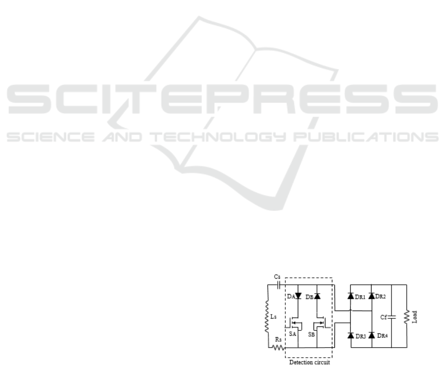
detection switch (Nutwong et al., 2019). These
communication types show high performances to
identify the receiver device with low power
consumption and use the coil themselves. It can be
implemented into the receiving side circuit before the
rectifier stage based on additional switches connected
to the receiving side circuit, as shown in Figure 1.
Meanwhile, it increases the circuit cost and volume.
Figure 1: Block diagram of the system.
EWSN-IoT 2022 - Special Session on Energy-Aware Wireless Sensor Networks for IoT
264
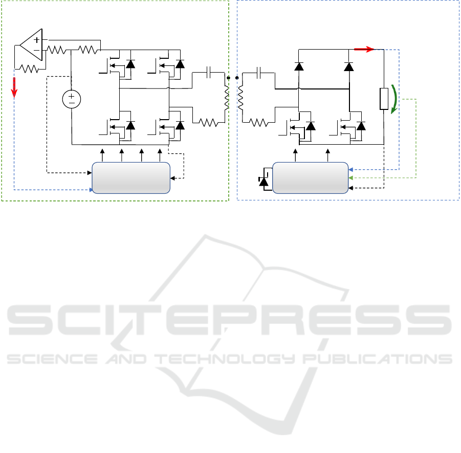
Figure 2: Schematic diagram of the proposed IPT system with control configuration.
On the other hand, for the secure charging of
supercapacitors, the CC current techniques are
required. Typically, various methods are proposed in
research to achieve the CC during the charging
process. This condition is important to increase the
supercapacitor lifetime. In (Mai et al., 2021), an S-SP
compensation topology is proposed to achieve the
CC. However, the proposed solution is valid for no or
just small misalignment conditions.
Other techniques use DC to DC converters after
the bridge rectifier, as proposed in (Somsak et al.,
2021), this method is not preferable in low-power
applications, where both output power and power
transfer efficiency can be highly affected because
even for using efficient DC to DC converters, bridge
rectifier consumes a lot of energy. Moreover, cost and
receiver volume will be increasing. For that, in (Na et
al., 2018), an active full-bridge rectifier is introduced
to achieve the CC, although the use of DC to DC
converters is not necessary in this case, a huge filter
is required.
The more efficient converter which is named by
the semi-active rectifier is presented in (Iam et al.,
2020). However, using the semi-active rectifier
allows the IPT system to dispense with using DC-DC
converters, resulting in increased system efficiency
and allowing to make direct power regulations
without extra components. The output of the semi-
active rectifier can be controlled by adjusting the duty
cycle or by changing the phase shift angle between
the pulses. Moreover, CC charging is also can be
achieved even when the conducting angle equal to
zero (Iam et al., 2020).
3 PROBLEM STATEMENT AND
PROPOSED SOLUTION
Designing an optimal IPT system requires a low-
power consumption with a secure power transfer and
compact size. To address the drawbacks of the
previous studies. A schematic of the proposed IPT
system is illustrated in Figure 2, this paper proposes
to use the semi-active rectifier on the secondary side
for the following reasons:
1- The size of this converter can fulfill the
compactness condition of the optimal IPT system.
2- It can be used to detect foreign objects by
applying the proposed control technique without
communication modules between the primary and the
secondary side.
3- To increase the efficiency of the proposed IPT
system, two different operating modes with high and
low power are introduced. However, the IPT system
selects the desired operation mode based on the semi-
active rectifier.
4- CC during the charging process can be
achieved even when the conducting angle is equal to
zero.
Numerous advantages can be achieved due to
using the semi-active rectifier. Compared to other
DC-DC converters, a semi-active rectifier reduces the
number of the used components, increases the system
efficiency, and decreases the receiver volume and
weight.
SC
VS
S1 S2 C1 C2 D1 D2
S3 S4 R1 R2 S5 S6
L1 L2
M
I1
IO
VO
Primary side
Secondary side
S1 S2 S3 S4 S5 S6
RB
RF
Shunt
MSP430
FR5969
GND
Vcc
ADC
A1
GND
A2
Vcc
Vcc
Z
MSP430
FR5969
Vcc
ADC
GND
A1 A2 A3 A4
A Compact Receiving Side Circuit for Wireless Power Transfer with Foreign Object Detection Technique
265
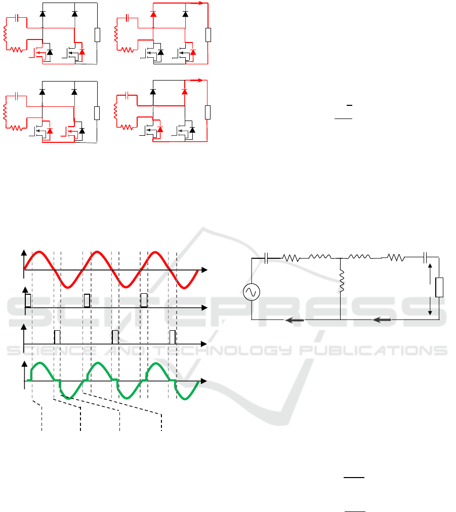
Figure 3: Operating modes of the semi-active rectifier. (a)
Mode I, (b) Mode II, (c) Mode III, (d) Mode IV.
Fundamentally, various operating sequences can
be used to control the output power of the semi-active
rectifier. However, the operating modes of the
proposed IPT system are depicted in Figure 3.
Figure 4: Proposed control operating waveform.
In Mode I, the current flows in the positive
direction, switch S5 is on so the current will pass
through this switch and the body diode of switch S6.
However, in this mode, no current passes to the load.
In Mode II, after the switch S5 is switched off, the
current still flows through the diode D1 and the body
diode of the switch S6. The supercapacitor will be
starting to charge in this mode.
The current flows in the negative direction in
Mode III, while switch S6 is on, the current will pass
through it and complete its path through the body
diode of switch S5. In this mode, the current stays in
the resonant tank, and no current passes to the
supercapacitor. In mode IV, switch S6 is switched off
and the current can pass to the supercapacitor through
the body diode of switch S5 and the diode D2.
Moreover, the operating waveform of the semi-active
rectifier is illustrated in Figure 4.
The proposed semi-active rectifier can be
controlled by adjusting the duty cycle (D) of both
switches in the range of (0-0.5). The root main square
(RMS) of the resonant tank output voltage (Ve) is
defined as Eq. 1.
(1)
4 PROPOSED FOD TECHNIQUE
For low-power applications, foreign objects in
proximity of the transmitter side can significantly
affect the IPT system parameters. To elaborate on
these effects, the general equivalent circuit of the IPT
system is illustrated in Figure 5.
Figure 5: T-model equivalent circuit of an IPT system.
Where Vs is the input voltage, V
O
is the output
voltage, I
P
, and I
O
are the primary and secondary
currents, respectively. R
1
is the resistance of the
primary coil and R
2
is the resistance of the secondary
coil, C
1
is the primary side compensation capacitor
and C
2
is the secondary side compensation capacitor.
The mathematical model of the IPT system can be
obtained by applying Kirchhoff's voltage law (KVL)
as depicted in Eq 2 and 3.
(2)
(3)
A metallic object can be represented as an
inductance with a series resistance, Meanwhile, it will
decrease the equivalent inductance of the system and
increase the equivalent resistance of it. This change
can also affect the input current.
Typically, the input current can be measured
either directly or using a differential amplifier and a
shunt resistor in series with the power supply. In low-
SC
C2 D1 D2
R2 S5 S6
L2
SC
C2 D1 D2
R2 S5 S6
L2
IO
SC
C2 D1 D2
R2 S5 S6
L2
SC
C2 D1 D2
R2 S5 S6
L2
IO
(a)
(b)
(c) (d)
Vin
Vout
S5
S6
Mode I
Mode II
Mode III
Mode IV
C1
C2
R1
R2
L1-M
VO
VS
L2-M
M
IP
IO
Z
EWSN-IoT 2022 - Special Session on Energy-Aware Wireless Sensor Networks for IoT
266
power applications, the input current range in the case
of misalignment is overlapping with the case of the
FOD, which increases the challenges. However,
measuring the input current is not sufficient to detect
foreign objects.
For such reasons, the controller of the secondary
side is also should be programmed to detect the
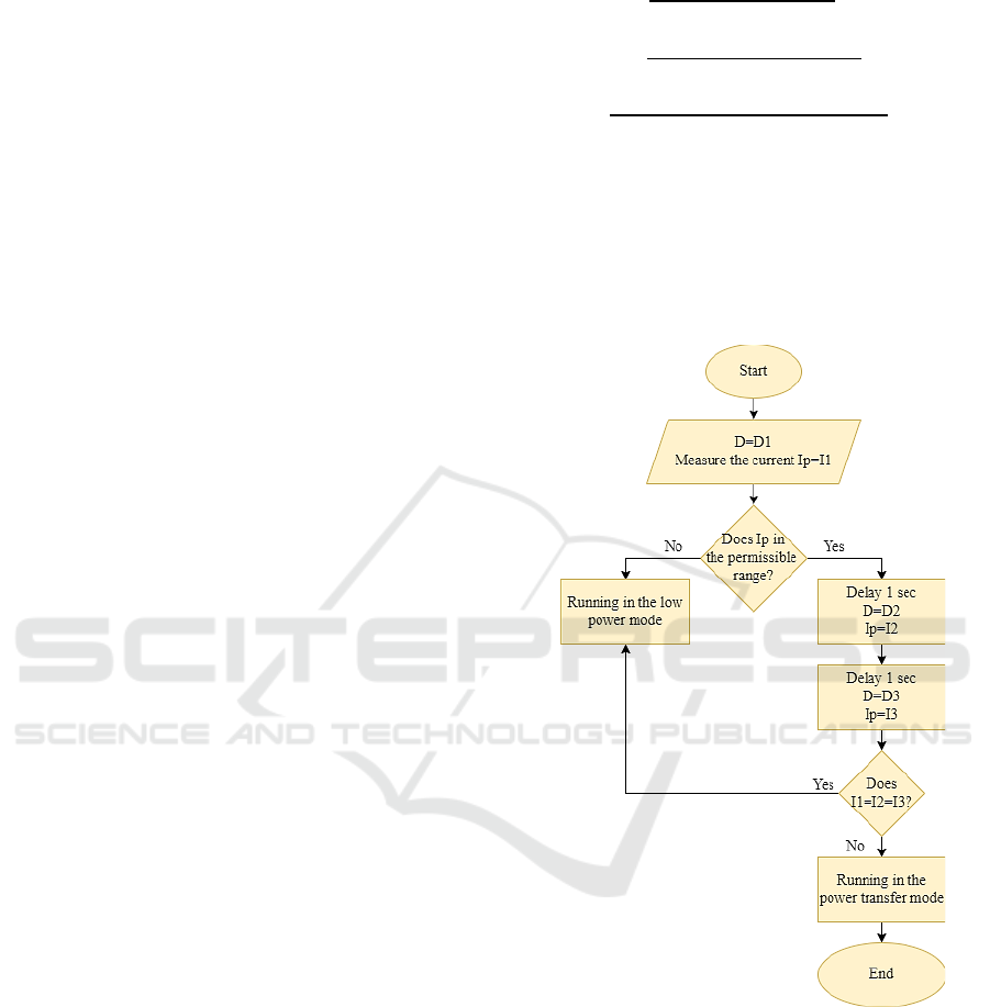
foreign object. Before transferring the power, the
semi-active rectifier begins its work at a certain duty
cycle (D=D1), at this moment the current sensor will
measure the primary current value (Ip= I1) if the
primary current is in the permissible range, the
controller after 1 sec will change the duty cycle to
(D=D2), and the primary current will be (Ip=I2).
After 1 sec, the duty cycle will change to (D=D3) and
the primary current will be (Ip=I3). However, this
process is called a detection process, in case of a
foreign object exists, the primary current will not be
affected by the changes in the duty cycle
(Ip=I1=I2=I3), in this case, the primary circuit will
back to the low power mode. Otherwise, if the amount
of current is changed, this means a permissible
receiver exists and the power transfer process will
begin
5 OPTIMIZING POWER
TECHNIQUE
The proposed technique can optimize the consumed
power at several bands. Firstly by getting rid of
communication between primary and secondary
sides. However, each part is required to control itself
independently. To achieve this goal, two modes of
operation that the primary side can work on are
proposed. The first one is the power transfer mode
and the second one is the low power mode. In the
power transfer mode, electric energy can be
transferred from the primary side to the load at a
certain power level and under the resonance
frequency. This process is valid only after making
sure that there are no foreign objects in the proximity
of the transmitter, as well as, a valid receiver is
existing. In the low power mode, the minimum output
power should be transferred to the secondary side. By
decreasing the input voltage, leads to a decrease in the
amount of output power.
From the previous equations, input power P
in
,
output power P
O,
and power transfer efficiency can
be simply obtained, as illustrated in Eq. 4, 5, and 6.
(4)
(5)
(6)
Both input power, as well as output power, are
related to the square of the input voltage. For that,
input and output power will be decreased when the
input voltage decreases. Moreover, the power transfer
efficiency doesn’t be affected by the amount of input
voltage. The flow chart of the control procedure is
illustrated in Figure 6.
Figure 6: Flowchart of the proposed control.
6 EXPERIMENT SETUP
The experimental prototype of the proposed IPT
system is illustrated in Figure 7. Moreover, the main
components and system parameters that are used in
the experiment are depicted in Table 1.
A Compact Receiving Side Circuit for Wireless Power Transfer with Foreign Object Detection Technique
267
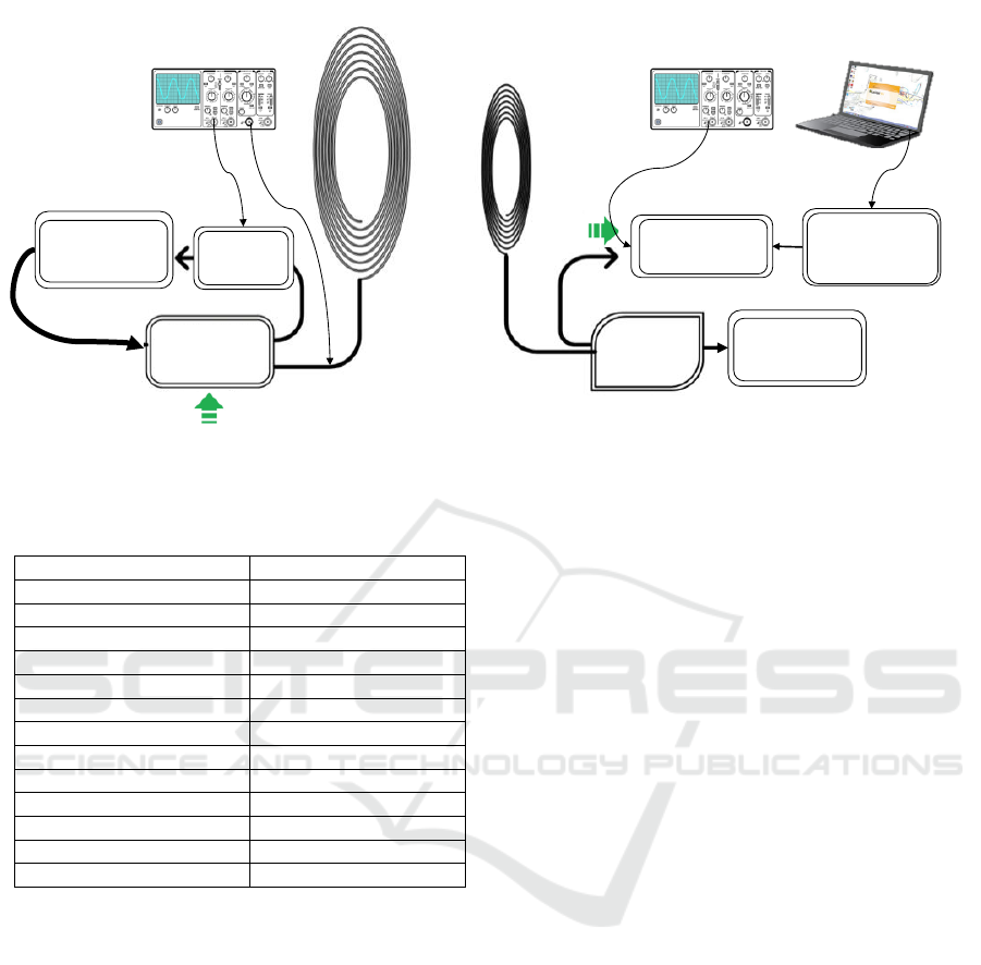
Figure 7: Experimental prototype of the proposed IPT system.
Table 1: System parameters.
Parameters
Values
Operating frequency
100 kHz
Voltage input
5 V
Coupling factor
0.6
Primary coil inductance
10 uH
Primary coil resistance
0.3 Ω
Secondary coil inductance
10 uH
Secondary coil resistance
0.1 Ω
Compensation capacitors
253.3 nF
Switches (S1-S6)
IRLZ44
Diodes (D1, D2)
UF4001
Supercapacitor
3 F, 5 V
Amplifier
LM324
Controller
MSP430FR5969
On the primary, side an MSP430FR5969 controller
is used to generate the pulses that are used to operate
the full-bridge inverter. Typically, MSP430FR5969
is used to generate the desired operating frequency.
Another reason to use the controller is to move
between the low power mode and the transfer power
mode. However, adjusting the duty cycle of the
output pulses changes the amount of generated
voltage.
A current sensor based on an LM324 differential
amplifier is used to measure the input current due to
its high gain, wide power supply range, very low
consumes power, and low input offset voltage and
current.
On the secondary side, the semi-active rectifier is
controlled by the MSP430FR5969 controller, the
mean reason for selecting this controller exactly is the
amount of consumed power compared to other
controllers. It consumes power ten times less than
other controllers (Gotz et al., 2020), where this
purpose is very important on the secondary side, a 3.3
V Zener diode is used to protect the controller from
any voltage variations.
It should be noted that even with the input voltage
of the secondary side less than 3.3 V, the semi-active
rectifier will work as a passive rectifier and the
supercapacitor can be successfully charged.
However, the FOD technique can be effective after
the controller is supplied. The output voltage is
continuously monitored by the controller, a voltage
divider circuit is necessary also to prevent the
malfunction of the controller.
Selecting the supercapacitor size is depending on
the application, the system parameters, and the
availability of charging time. Typically, the size of
the supercapacitor C
storage
can be calculated based on
Eq. 7.
(7)
Where E
WSN
is the energy of the WSN, V
high
and
V
low
are the upper and lower threshold of the
supercapacitor, respectively.
WSN
is the WSN
efficiency.
The DAC software is also used to collect some
data from the IPT system like the detection behavior
and charging times in different cases, it needs an
Arduino controller connected with a PC.
Full-bridge
inverter
Current
sensor
Semi-active
rectifier
MSP430
FR5969
Supercapacitor
/ WSN
Oscilloscope
Arduino DAQ
Transmitter coil
Receiver coil
Input power
Output power
Oscilloscope
Arduino Uno
MSP430
FR5969
EWSN-IoT 2022 - Special Session on Energy-Aware Wireless Sensor Networks for IoT
268
7 RESULTS AND EVALUATION
To evaluate the proposed IPT system, different cases
are tested: no object or receiver, valid receiver, and
foreign object in the proximity of the transmitter.
Moreover, the same experiments are repeated with
misalignment between the coils to investigate the
output results under this condition.
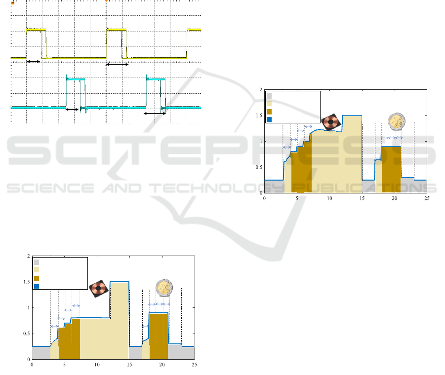
The generated pulses of the secondary side
controllers are illustrated in Figure 8. The pulses are
generated to satisfy the control method requirements,
the duty cycle for both switches is changed during the
detection mode.
Figure 8: Semi-active rectifier switches during the duty
cycle changes.
Initially, when no receiver coil or a foreign object
is in the proximity of the sending side, it is operated
in the low-power mode, any variation of the input
current triggers the controller to work on the power
transfer mode and the detection mode will be starting.
Figure 9 illustrates the input current behavior in
different modes.
Figure 9: Input current at different conditions.
In the first three seconds, the proposed system was
working on the low-power mode, the amount of the
input current is 0.25 A, then the receiver coil is
located in the proximity of the transmitter, for that,
the input current is changed and the mode of
operation is moving to the detection mode, variations
of the duty cycle during three seconds are enough to
increase the current from 0.6 to 0.8 A, resulting in the
detecting of the receiver then the power transfer is
starting with around 0.82 A. After three seconds, the
receiver is removed and the operation mode is still in
the power transfer mode, so the current increases to
1.5 A. When the input current is equal to the no-load
current for three seconds the system moves to the low
power mode. Per second 17, a 2 euro coin is situated
in the proximity of the transmitter. Input current is
varying and the operation mode is moved to the
detection mode. It's obvious from the figure that the
variation of the duty cycle didn’t change the amount
of the input current, it is fixed around 0.9 A, so the
system is moved to the low power mode. Moreover,
per second 23, the foreign object is removed and the
system is still in the low-power mode.
The same procedure is repeated with a
misalignment of 8 mm between the transmitter and
receiver, the result is demonstrated in Figure 10.
Figure 10: Input current at different conditions with
misalignment.
The only difference between the two cases is what
happens during the transfer of the power to the
receiver coil. The input current in the power transfer
mode increases from 0.8 to 1 A in the detection mode
and around 1.2 A in the power transfer mode.
Moreover, when the coin is in the proximity of the
transmitter, the same behavior of the no-
misalignment case is formed.
The supercapacitor takes around 40 sec to be fully
charged in the case of no-misalignment, the output
current is around 330 mA, it is obvious from the
figure that the current is almost constant during the
charging process. However, 17 sec are required to get
the controller desired voltage, this means, the FOD
method can start working after this period.
S5
S6
D2
D1
D1
D2
F=100 kHz, 2 V/div
D1
D2
D3
No
device
No
device
Coin
No
device
ΔI
ΔI
D1
D2
D3
No
device
Low power mode
Power transfer mode
Detection Mode
mode
Input current
Time in sec
Current in A
Receiver
D1
D2
D3
No
device
No
device
Coin
No
device
ΔI
D1
D2
D3
No
device
Low power mode
Power transfer mode
Detection Mode
mode
Input current
Receiver
Current in A
Time in sec
ΔI
A Compact Receiving Side Circuit for Wireless Power Transfer with Foreign Object Detection Technique
269
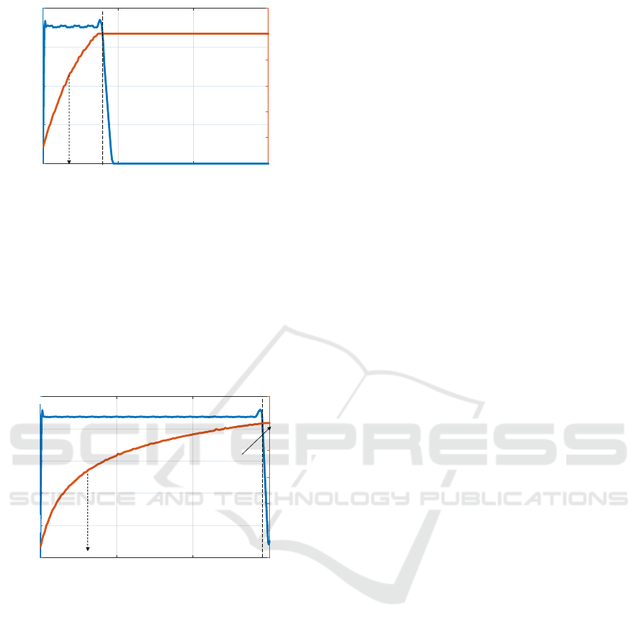
Figure 11: Charging current and voltage with no
misalignment.
An 8 mm misalignment between the coils is also
considered, in this case, the supercapacitor requires
150 sec to complete the charging process, while the
current charging is 90 mA. The CC of charging also
exists even with this amount of misalignment.
However, the 3.3 V can be obtained after 32 sec,
where the controller can start to detect foreign
objects, as illustrated in Figure 12.
Figure 12: Charging current and voltage with an 8 mm
misalignment.
Typically, the consumed power level depends on
the used WSN and the mode of operation. For
example, WSN based on ARM Cortex-m3
microprocessor consumes 500mW with 5V in active
power mode and 80PW in sleep power mode. In this
case, the proposed system can supply the WSN
continuously in the sleeping mode and more than one
minute in the active power mode per charge.
However, it is considered very well because the
charging time is about 40sec with no misalignment
between the coils and about 150sec in the worst case.
The power supplying time will be changed if another
type of WSN is used. A lot of WSN’s consume much
less power than the ARM Cortex-m3.
8 CONCLUSIONS
This paper introduced an IPT system with a
communication-free between the primary and the
secondary sides. An efficient semi-active rectifier is
controlled by the proposed method to charge
supercapacitors, especially for WSN applications.
Both analytical and experimental results show that the
proposed control technique success to detect foreign
objects in the proximity of the transmitter side.
Optimizing the power consumption is also considered
using two different types of operation mode; power
transfer mode and low-power mode. In the case of no
receiver detecting or foreign object existing in the
proximity of the transmitter, the primary side
controller decreases the input voltage by adjusting the
duty cycle, resulting in activating the low-power
mode. Compared to other studies, the proposed
system has many benefits, such as compactness,
sensorless, communication-free, and the security of
charging. These benefits give a great advantage to
using the proposed technique instead of other limited
ones.
ACKNOWLEDGEMENTS
The authors would like to thank the DAAD for the
support through the projects " International Winter
school on smart E-Helth (Smart E-Health)
57599935", and the Federal Ministry for Economic
Affairs and Energy and AIF for funding the project
"(Weartrack) Research grant AIF-ZIM
ZF4075906S09" within the Central Innovation
Program for SMEs (ZIM)
REFERENCES
Kanoun, Olfa, Sabrine Khriji, Slim Naifar, Sonia Bradai,
Ghada Bouattour, Ayda Bouhamed, Dhouha El
Houssaini, and Christian Viehweger. 2021. "Prospects
of Wireless Energy-Aware Sensors for Smart Factories
in the Industry 4.0 Era" Electronics 10, no. 23: 2929.
Bouattour, Ghada, Mohamed Elhawy, Slim Naifar,
Christian Viehweger, Houda Ben Jmaa Derbel, and
Olfa Kanoun. 2020. "Multiplexed Supply of a MISO
Wireless Power Transfer System for Battery-Free
Wireless Sensors" Energies 13, no. 5: 1244.
Bouattour, G., Kallel, B., Derbel, H. and Kanoun, O., 2019.
Passive Peak Voltage Sensor for Multiple Sending
Coils Inductive Power Transmission System. 2019
IEEE International Symposium on Measurements &
Networking (M&N),.
CC mode
CV mode
17
0
0
0.1
0.2
0.3
0.4
50 100 150
0
1
2
3
4
5
6
Voltage in V
Time in sec
Current in A
CV mode
32
0
0
0.2
0.4
0.6
0.1
50 100 150
0
1
2
3
4
5
6
Voltage in V
Time in sec
Current in A
CC mode
0.8
EWSN-IoT 2022 - Special Session on Energy-Aware Wireless Sensor Networks for IoT
270

Adawy, A., Bouattour, G., Ibbini, M., Derbel, N. and
Kanoun, O., 2021. Sliding Mode Control of an
Inductive Power Transmission System with Maximum
Efficiency. 2021 18th International Multi-Conference
on Systems, Signals & Devices (SSD),.
Adawi, A., Bouattour, G., Ibbini, M., & Kanoun, O. (2020).
Design and Control of an Inductive Power
Transmission System with AC-AC Converter for a
Constant Output Current. In 2020 17th International
Multi-Conference on Systems, Signals & Devices
(SSD). 2020 17th International Multi-Conference on
Systems, Signals & Devices (SSD). IEEE.
Mai, J., Wang, Y., Yao, Y. and Xu, D., 2021. Analysis and
Design of High-Misalignment-Tolerant Compensation
Topologies With Constant-Current or Constant-
Voltage Output for IPT Systems. IEEE Transactions on
Power Electronics, 36(3), pp.2685-2695.
Shi, W., Dong, J., Soeiro, T. and Bauer, P., 2021. Integrated
Solution for Electric Vehicle and Foreign Object
Detection in the Application of Dynamic Inductive
Power Transfer. IEEE Transactions on Vehicular
Technology, 70(11), pp.11365-11377.
Shi, W., Grazian, F., Dong, J., Soeiro, T. and Bauer, P.,
2020. Detection of Metallic Foreign Objects and
Electric Vehicles Using Auxiliary Coil Sets for
Dynamic Inductive Power Transfer Systems. 2020
IEEE 29th International Symposium on Industrial
Electronics (ISIE),.
Hoffman PF, Boyer RJ, Henderson RA. Foreign object
detection system and method suitable for source
resonator of wireless energy transfer system. Apr. 5,
2016. U.S. Patent 9,304,042 B2.
Bell D, Leabman MA. Systems and methods of object
detection using one or more video cameras in wireless
power charging systems. Jan. 16, 2018. U.S. Patent
9,871,387 B1.
Zhang, Y., Yan, Z., Zhu, J., Li, S. and Mi, C., 2019. A
review of foreign object detection (FOD) for inductive
power transfer systems. eTransportation, 1, p.100002.
Jung, H. and Lee, B., 2021. Wireless Power and
Bidirectional Data Transfer System for IoT and Mobile
Devices. IEEE Transactions on Industrial Electronics,
pp.1-1
Karimi, M., Schmid, A. and Dehollain, C., 2021. Wireless
Power and Data Transmission for Implanted Devices
via Inductive Links: A Systematic Review. IEEE
Sensors Journal, 21(6), pp.7145-7161.
Barbruni, G., Asti, F., Ros, P., Ghezzi, D., Demarchi, D.
and Carrara, S., 2021. A 20 Mbps, 433 MHz RF ASK
Transmitter to Inductively Power a Distributed
Network of Miniaturised Neural Implants. 2021 IEEE
International Symposium on Medical Measurements
and Applications (MeMeA),.
Yenil, V. and Cetin, S., 2021. Constant Voltage Control of
A Double Sided LCC Compensated IPT Converter
Based On Pulse Density Modulation. 2021 IEEE 19th
International Power Electronics and Motion Control
Conference (PEMC),.
Nutwong, S., Sangswang, A. and Naetiladdanon, S., 2019.
An Inverter Topology for Wireless Power Transfer
System with Multiple Transmitter Coils. Applied
Sciences, 9(8), p.1551.
Somsak, T., Namin, A., Sriprom, T., Thongpron, J.,
Kamnarn, U. and Patcharaprakiti, N., 2021. Constant
Current - voltage with Maximum Efficiency Inductive
Wireless EV Charging Control using Dual - sides DC
Converters. 2021 18th International Conference on
Electrical Engineering/Electronics, Computer,
Telecommunications and Information Technology
(ECTI-CON),.
Na, K., Ma, H., Namgoong, G., Kim, K., Jung, J. and Bien,
F., 2018. Step‐charging technique for CC/CV mode
battery charging with low‐cost control components in
IPT systems. IET Power Electronics, 11(15), pp.2523-
2530.
Iam, I., Hoi, I., Huang, Z., Gong, C., Lam, C., Mak, P. and
Martins, R., 2020. Constant-Frequency and Non-
Communication-Based Inductive Power Transfer
Converter for Battery Charging. IEEE Journal of
Emerging and Selected Topics in Power Electronics,
pp.1-1.
Gotz, M., Khriji, S., Cheour, R., Arief, W. and Kanoun, O.,
2020. Benchmarking-Based Investigation on Energy
Efficiency of Low-Power Microcontrollers. IEEE
Transactions on Instrumentation and Measurement,
69(10), pp.7505-7512.
A Compact Receiving Side Circuit for Wireless Power Transfer with Foreign Object Detection Technique
271
