
Digital Surface Model Generation with Aerial Surveying System
“LEICA ADS80”
Vojkan Stanojević
1
, Zlatan Milonjić
1
, Dejan Đorđević
1
, Saša Bakrač
1,2 a
, Marko Stojanović
1,2 b
and Zoran Stevanović
3
1
Military Geographical Institute, Mije Kovačevića 5, Belgrade, Serbia
2
Military Academy, University of Defence, Veljka Lukica Kurjaka 33, Belgrade, Serbia
3
Ministry of Defence Republic of Serbia, Birčaninova 5, Belgrade, Serbia
stojanovicm80@yahoo.com, zoran.stevanovic.steki@gmail.com
Keywords: LiDAR, Digital Surface Models, Algorithms, Pushbroom Scanner, Semi-Global Matching, Orthorectification.
Abstract: The aerial imaging system LiDAR is data collection technology for Digital Surface Models (DSM) and Digital
Elevation Models (DEM). Digital line Pushbroom scanner Leica ADS80 can be used to obtain DSM / DEM
thanks to the recorded material. The data obtained using the ADS80 provide several advantages over LiDAR
results, especially since the generation of orthophotos can be based on the same data set. As a fundamental
approach, the principle of Semi-Global Matching (SGM) it is used, which is suitable for the process of
calculating digital models of high-performance and high-resolution surfaces. This paper presents the SGM
approach during processing images obtained by the ADS80 system, as well as comparing the results obtained
using the LiDAR system - in terms of data processing. A comparative analysis and comparison of SGP and
LiDAR ALS80 HP properties was performed, which is illustrated on a specific example. It has been shown
that SGM can be used as an alternative to the LiDAR system. For certain applications for which it is necessary
to generate a digital model of a high-resolution surface or to make orthophotos - thus saving additional flight
costs - SGM is the priority choice.
1 INTRODUCTION
In the last decade an aerial scanning system known as
LiDAR (Light Detection and Ranging) has been
affirmed as a key technology for obtaining high-
resolution digital surface models (DSM) as well as/or
for obtaining digital elevation models (DEM). At the
same time, there is a growing need to improve the
accuracy and higher resolution of digital surface
models and digital elevation models. The LiDAR
system is usually used to meet the above requirements
for various needs, including obtaining orthophotos.
However, considering the significant cost of
procurement, its use only for orthorectification
purposes is avoided. Taking into account the fact that
the application of the aerial photogrammetric
recording camera ADS80 from Leica Geosystems
provides multiple stereo coverage, the recorded
material can and should be used for photogrammetric
a
https://orcid.org/0000-0003-0211-3765
b
https://orcid.org/0000-0002-2193-1483
acquisition of digital surface models. Therefore, in
addition to the LiDAR system intended for data
acquisition, there is a need to develop procedures-
algorithms for generating digital surface models
based on data recorded by the ADS80 line scanner - a
digital camera for aerial photogrammetric recording.
Depending on the size of the pixels in the field
(Ground Sampling Distance - GSD), a high-
resolution DSM is generated, striving to match the
current image resolution. In other words, each point
of generated DSM corresponds to one pixel.
Algorithms that minimize both values and various
constraints at the global level are called global image
matching and are ranked among the best algorithms
in terms of achieving high quality and resolution. The
advantages of these algorithms are the performance
related to the Semi-Global Matching (SGM) principle
developed by Hirschmüller (Hirschmüller, 2008;
Hirschmüller and Bucher, 2010).
Stanojevi
´
c, V., Milonji
´
c, Z., Dordevic, D., Bakra
ˇ
c, S., Stojanovi
´
c, M. and Stevanovi
´
c, Z.
Digital Surface Model Generation with Aerial Surveying System “LEICA ADS80”.
DOI: 10.5220/0011026700003185
In Proceedings of the 8th International Conference on Geographical Information Systems Theory, Applications and Management (GISTAM 2022), pages 107-114
ISBN: 978-989-758-571-5; ISSN: 2184-500X
Copyright
c
2022 by SCITEPRESS – Science and Technology Publications, Lda. All rights reserved
107
Semi-global matching approximates two-
dimensional, global aggregation of value matching by
a number of one-dimensional value trajectories.
Similar accuracy is still achieved as the application of
full global matching, but much faster - such as by
systematically comparing SGM with local and global
matching algorithms using different value functions
according to Hirschmüller and Scharstein
(Hirschmüller and Scharstein 2007; Szeliski, 2010).
As a result, SGM is further researched and improved
by different researchers for different types of
applications and data sets including aerial
photographs, terrestrial and satellite data or video
sequences.
It has been noticed that SGM meets customers
need for a high-resolution, high-performance digital
surface model. Taking into account the fact that the
SGM principle is well accepted with regard to the
quality of the results, the algorithm is adapted to the
unique properties of the ADS80 line Pushbroom
scanner using the existing software environment, with
a special highly optimized module.
The rest of this paper describes the process of
obtaining a digital surface model based on ADS80
data based on the SGM principle.
2 SEMI-GLOBAL MATCHING
SGM represents an approach to image (Hu at al.,
2015). The essence of the algorithm is in the method
of solving the coincidence or pairing of individual
identical parts of stereo pairs, so that the principle of
SGM is based on computer vision. Images
(snapshots) usually represent a two-dimensional
projection of a three-dimensional world.
2.1 Algorithm
To generate a digital surface model of the expected
accuracy, it is necessary to ensure the redundancy of
the input data, which is achieved thanks to multiple
images with a continuous pushbroom scanning with
100% overlapping. Since it is generated using
stereoscopic images, the DSM is usually represented
by a landscape dome which contains elevation
information about all the details above the surface,
including the tops of buildings in trees (Milonjic et
al., 2016).
Digital system for aerial photogrammetric
recording ADS80 represents the integration of three
technologies into one system for data collection in
digital form:
Sensor Head (SH82),
Global Positioning System (GPS) and
Inertial Navigation System (INS) also known
as Inertial Measurement Unit (IMU).
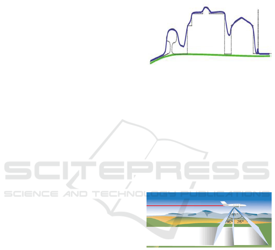
Figure 1: Display of actual shapes (black), digital surface
model (blue) and digital terrain model (green).
Their combination can determine the coordinates
of points on the earth's surface with high accuracy.
As mentioned, the complete solution for
generating DSM is presented with Leica XPro
software, ie. DSM Extraction module based on Semi-
Global Matching principle.
Computer spatial stereo vision refers to the
registration of data, ie, the capture of images from two
or more cameras that are horizontally spaced from
each other (from different databases). In the case of
the ADS80 digital aerial photogrammetric recording
system, this was achieved by using a Pushbroom line
scanner with three shooting angles: backward - nadir
- forward:
Figure 2: Three different shooting angles.
In this way, it is possible to capture objects from
different angles (each object is captured three times),
so that based on the analysis of similarities and
differences in views, parameters used in computer
vision applications such as the reconstruction of the
original three-dimensional scene can be calculated.
So, each object and scene are recorded three times,
where, at first glance, they are slightly different. By
comparing derived stereo pairs, additional
information about the depth of the scene can be
obtained. The process of obtaining the depth of a
scene from a stereo pair is called space calculation
(Zhang et al., 2017).
GISTAM 2022 - 8th International Conference on Geographical Information Systems Theory, Applications and Management
108
Since the geometry of the camera is known, it can
be concluded that the base distance B = C
l
- C
r
is
constant. Comparing similar triangles, it is possible to
determine the distance to the point (X, Y, Z) of the
object in space or the depth of the object Z by
applying triangulation:
f
x
Z
X
l
and
f
x
Z
BX
r
(1
)
so that the following equation can be derived:
d
fB
xx
fB
Z
rl
(2)
The problem of pairing identical points or areas
based on stereo pairs is called the matching problem,
where the procedure is performed by algorithms that
include searching and comparing details. This process
can be greatly simplified by introducing certain
assumptions and limitations into the algorithms. The
assumptions applied in the algorithms of SGM
principles are:
epipolar correction,
Uniqueness pairing,
smooth surface,
pairing order.
2.1.1 Epipolar Correction
If the camera geometry is known, two-dimensional
search of matching points on images can be
simplified by one-dimensional search by applying
image correction based on epipolar geometry (Wang
et al., 2018).
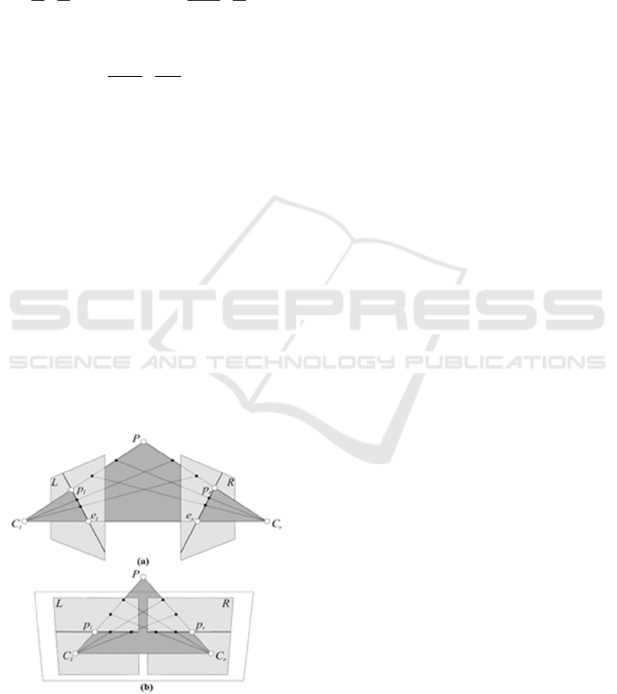
Figure 3: Epipolar correction.
The epipolar correction of the images is shown in
Figure 3. The optical centres of the two cameras are
represented by points C
l
and C
r
, while a point on the
earth's surface is represented by point P. The
projection of that point P in the plane of the left
camera L is at point p
l
, and in the plane of the right
camera R is at point p
r
. Any other point located in the
P-C
l
direction will be projected on the p
r
-e
r
direction
called the epipolar projection line p
l
, where e
r
represents the epipole where geometrically represents
the image of the optical center of the left camera C
l
in
the right camera. The points can be projected in the
same way in the left chamber as in Figure 3a.
Correction of the images is achieved by straightening
the planes L and R so that p
l
-e
l
and p
r
-e
r
form a line in
the same plane as in the figure 3b:
If the projections of all points are corrected in the
same way, the result is that the matching elements of
the stereo pair are on the same horizontal line, which
allows the matching problem to be simplified and
solved by searching only in the direction of one axis:
x
r
= x
l
+ d while
y
r
=
y
l
(3
)
In equation (3), the value d represents the
horizontal shift between two matching elements of
the image called the disparity. By calculating the
disparity for all elements of the image, a disparity
map is obtained.
2.1.2 Uniqueness of Pairing
The details in the stereo pair must be uniquely paired
to allow further processing in computer stereo vision
applications (Ye et al., 2018). This means that an
element of one image is paired with only one element
of another image. If the image contains large regions
of constant intensity (monochrome parts), then within
such a region a point from one image based on the
same intensity can be paired with any point or more
of them within the same region on another image and
vice versa. The biggest problem with stereo pair
pairing occurs due to the fact that certain elements do
not exist on both images. This phenomenon occurs
because not all details are visible for all cameras,
example, some scene parts are sheltered by objects
even though they are visible to another camera
(Figure 4).:
If there is no possibility of matching an element
of the image, the depth for that element cannot be
calculated and it is said that this element is sheltered
for another camera.
Digital Surface Model Generation with Aerial Surveying System “LEICA ADS80”
109
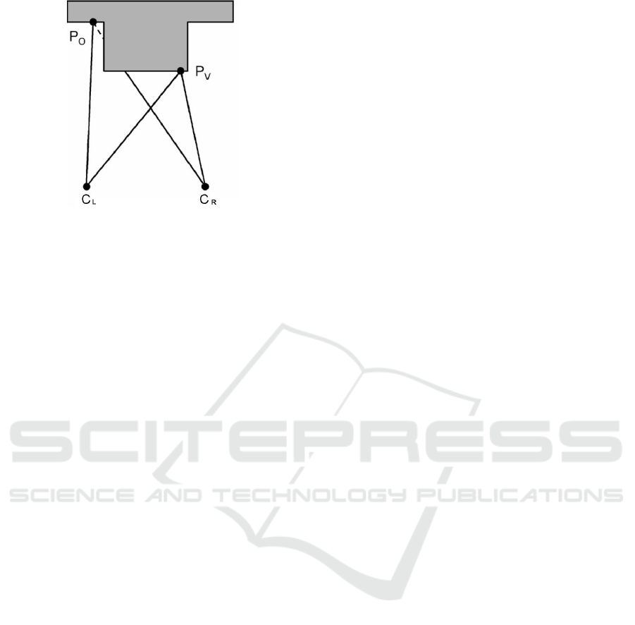
Figure 4: Example of shelter: P
V
- visible point for both
cameras; P
0
- sheltered point for the right camera.
Uniqueness pairing is applicable for opaque
surfaces. For transparent surfaces, one element of the
image can have two depths - the depth of the
transparent surface as well as the depth of the surface
in the background that is visible through the
transparent surface. The problem with uniqueness
pairing also occurs with oblique surfaces when during
the left and right projection of the same line there is a
difference in the projection length.
2.1.3 Smooth Surface
In terms of disparity, the smoothness of the objects
surface means that the values of disparities of
adjacent points differ very little. Larger differences in
the value of disparity occur at the boundaries of
objects where depth jumps occur between adjacent
elements of the image. Applying the surface
smoothness assumption increases the efficiency of
the stereopair pairing algorithm.
2.1.4 Pairing Order
If could be noticed two points of the scene P1 and P2,
whereby on one image the projection p1L of the point
P1 is located to the left of the projection p2L of the
point P2, then, in the case of the correct pairing
sequence, on the second image the projection p1R of
the point P1 is located to the left of the projection p2R
of the point P2. The assumption of such a pairing
sequence can be applied to most real scenes, and the
pairing order may change in certain situations.
The easiest way to pair the images is to pair each
element of one image individually with an element of
another image that completely matches or is most
similar to that element in terms of colour and contrast.
This approach, which is based on the pairing of
individual pixels, does not assume the smoothness of
the surfaces, i.e., the continuity of the disparity values
within the surfaces, whereby results with incorrectly
paired elements can be obtained. The cause of errors
when pairing individual pixels is found in a large
number of “candidates” that can match in colour. In
order to overcome this problem, the simplest
implementation of the surface smoothness
assumption is that adjacent pixels have a constant
disparity value. If a “window” is formed (for instance
of the size of 8x8 of image elements), for such a
window can be calculated the sum of the absolute
values of the differences in the intensity of individual
pixels within the window (Sum of Absolute
Differences), the sum of the absolute values of the
squares of the intensity of individual pixels within the
window (Sum of Squared Differences), a normalized
circular-correlation function or some other function
that measures the intensity of a window. By dragging
windows through the left and right images and
comparing the window intensity measure, windows
of the most similar intensity can be paired. Since the
window intensities are compared, it is possible to
calculate the disparity for the whole window, so that
for each element of the image inside the window (x,
y) a three-dimensional structure (x, y, d) is obtained
which is called the Disparity Space Image.
The biggest challenge when pairing certain parts
of the image using windows is choosing the window
size. If the windows are too small, errors may occur
as when pairing individual pixels due to the large
number of pairing candidates. In contrast, if larger
windows are used, the possibility of pairing the wrong
parts is reduced but an error occurs due to local
treatment of smoothness (constant disparity values
within the window) on the oversized part of the
image. The best results of pairing the appropriate
parts of the image using windows are achieved by
applying a variable window size in such a way that
smaller windows are used near depth jumps, while
larger windows are used in places that are further
away.
This value function is most used in semi-global
matching and is called the Mutual Information (MI)
function. MI function depends on entropy H both
from individual images and from the common
entropy of stereo pairs H
1,2
as well:
MI
1,2
=
H
1
+
H
2
(D) –
H
1,2
(4
)
By using quality images, the value of the common
entropy is small because one image can be predicted
by another, which increases their common
information (MI). All stereo image pairing algorithms
define a pairing consumption function when
performing a process of pairing pixels with common
information. The pairing consumption function is the
GISTAM 2022 - 8th International Conference on Geographical Information Systems Theory, Applications and Management
110
smallest for exact pairing and vice versa, in case of
incorrect pairing the pairing consumption function
increases.
The SGM approach is suitable for generating a
high-resolution DSM which matches the pixel value
in the field (Ground Sample Distance - GSD).
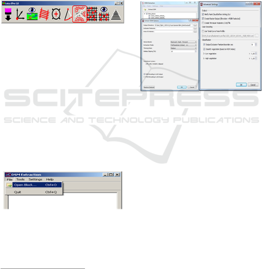
2.2 DSM Generation
The complete solution for generating DSM (Yang et
al., 2020) is presented with the Leica Xpro software
with DSM extraction module:
Figure 5: Leica XPro software main window (starting the
DSM Extraction module).
Software Leica Xpro consists of several modules
(applications). Unlike other modules, a module DSM
Extraction takes up the most system memory, so it is
necessary to provide a minimum of 8 gigabytes of
RAM for its operation. Since the significant time is
spent during the process of generating digital surface
models, it is recommended to use a local network of
high-performance computers (High Performance
Computing – HPC).
2.2.1 Input Data - Selection of Blocks and
Recordings Rows
As input data are used ADS L0
3
images (recording
rows) which are previously inserted in the Block
(module Block Preparation). The images can be of the
panchromatic or infrared spectrum and must have a
pyramidal structure formed.
Figure 6: Opening the block.
2.2.2 Defining Options for DSM Generation
After loading the block and selecting images to
generate DSM, additional adjustment of the digital
surface model extraction was performed:
3
Georeferenced images without radiometric and geometric
correction (
“raw” images).
Exclusion features (exclusion from the
generation process) and Area of Interest – for
this step is necessary to provide shape file with
defined coordinate system (*.prj file); if
coordinate system (*.prj) file was not provided,
the module would use automatically WGS84
coordinate system,
Stereo Bands – selection of stereo coverage,
where the following variants are possible:
- panchromatic: Backward – Nadir – Forward
- panchromatic: Backward – Nadir
- infrared: Backward – Nadir
Figure 7: Defining options for DSM generation.
To generate DSM using two stereo angles is a
significant waste of time but also better coverage of
point cloud. Otherwise, in specific cases (snow, etc.),
the use of the infrared spectrum is recommended
(Yang et al., 2020).
Possible variants of digital surface model
generation:
Quick – a fast generation method used to gain
insight into the appearance of the model. The time
to generate the model is very short, but the point
density is also low,
Full Resolution – full resolution - used for
orthorectification purposes. After processing of
the obtained point cloud, it is possible to derive a
digital terrain model (DTM),
Full Resolution (Urban) – the full resolution for
urban areas is applied for the purposes of
modelling and visualization of urban areas. After
processing of the obtained point cloud, a digital
surface model can be derived (DSM).
There are three different degrees of point filtering:
Mild – slightly, where the eye is filtered 95 %
points,
Digital Surface Model Generation with Aerial Surveying System “LEICA ADS80”
111
Medium – mediocre, where the eye is filtered 97
% points and
Aggressive – aggressively, where the eye is
filtered 99 % points.
After the generation process is completed, the
following results are obtained:
A file with a dense point cloud in the format LAS
1.2,
A file with a refined point cloud in the format las
1.2 and
Processing results (*.log files).
All points contain GPS time of registration
(recording) in Nadir. Depending on need, the outputs
may contain both RGB and FCIR information.
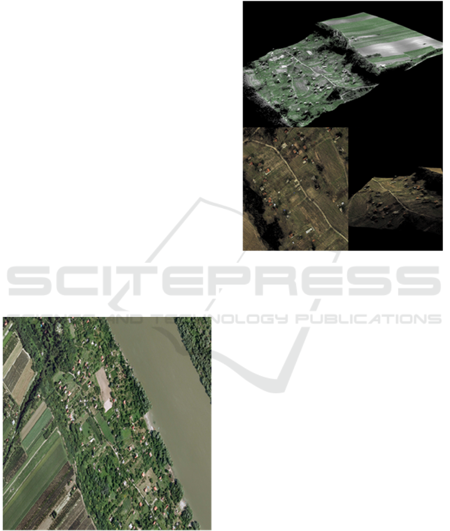
3 RESULTS OF DIGITAL
SURFACE MODEL
GENERATION
The generation of a digital surface model was
performed using aerial survey data of urban area
Slankamen. The set of equipment consists of the Piper
Seneca V aircraft from the American manufacturer
Piper Aircraft and digital aerial photogrammetric
camera ADS80 from the Swiss manufacturer Leica
Geosystems AG, as well as the associated software.
Figure 8: Slankamen - test area.
The digital surface model was generated using the
module DSM Extraction, while data preparation was
done using the appropriate software modules Leica
XPro.
Figure 9: Details of the digital surface model - terrain
profile.
Similar to the Leica ADS80 digital aerial
photogrammetric camera, LiDAR is the result of
integrating three technologies into one system:
Laser Scanning and Ranging System,
Global Positioning System – GPS,
Inertial Navigation System – INS (also known as
Inertial Measurement Unit – IMU) for registering
position changes between two GPS readings, as
well as to determine orientation and
RGB/NIR (Red-Green-Blue/Near Infrared) high
resolution camera (optional).
Laser scanning represents a method of collecting
digital spatial data. The principle of the LiDAR
system is based on the emission of a high-frequency
laser beam that is partially reflected and partly
absorbed by the ground or other objects in space. The
time difference between the emitted and reflected part
of the laser beam gives the length between the
instrument and the points on the field, while the
coordinates of the points are obtained based on
measured distances, laser beam angles (mirror angles)
and elements of external orientation.
As an example of new technology for generating
digital surface models, the ADS80 system is
increasingly being used as an alternative. Digital
GISTAM 2022 - 8th International Conference on Geographical Information Systems Theory, Applications and Management
112

surface models are generated based on images taken
in ideal conditions (angle of sunlight, avoidance of
clouds and turbulence, ...). The accuracy of DSM
generation depends on the accuracy of aero
triangulation - about 0.5 GSD in position and about
1.5 GSD in height, whereby turbulence during flight
can affect the reduction of image quality; thus, and to
reduce the quality of DSM. Typical high resolution is
up to 5 cm and only top of the surface is measured
with processing time of 10.000-20.000 pts/s.
Considering LiDAR, vertical accuracy is up to 5 cm,
both top and ground of the surface are measured with
processing time of 1.000.000 pts/s.
In both cases, DSMs with many points are
obtained, so additional processing is necessary prior
to usage for certain purposes. The data can be
classified automatically with the aim of determining
a digital terrain model (DTM), urban areas or
vegetation with minimal manual interventions.
Significantly higher points density obtained by
applying the SGM algorithm facilitates the
identification of the data structure and reduces errors
during manual editing. In addition, the advantage in
addition to the possibility of using image matching
procedures is in the geometry of the image and the
continuous processing of the recorded aerial data
(Yang et al., 2020).
4 APPLICATION
Basic survey (very suitable for orthorectification),
Storing altitude data for the purposes of making
digital topographic maps,
Production of digital and analogue orthophoto
plans and maps,
Solving the problem of construction profiles in the
design of roads and military engineering projects,
Three-dimensional representations of landforms
and flight simulations,
Landscape architecture and spatial planning (3D
modelling of urban areas for the needs of spatial
analysis and visualization),
Surveillance analyses,
Management of natural resources and
aboveground infrastructure (data can be used for
classification of vegetation, forests, calculation of
forest wood volumes as well as for development
of information system of natural resources),
Communication planning,
Determining locations for dams and bridges,
Hydrological and ecological modelling,
Hydraulic modelling simulation,
Analysis of geomorphological parameters
(exposure, slopes, curvature of the terrain),
Basis for other types of spatial information
(satellite images, thematic maps, etc.)
5 CONCLUSION AND
PERSPECTIVES
This paper presents the acquisition of digital surface
models using the principle based on Semi-Global
Matching (SGM) using data obtained by ADS80
pushbroom scanner, as well as a comparison of
ADS80 and LiDAR systems. It can be concluded that
by applying the SGM principle can be derived very
consistent surface models comparing with the models
derived by the LiDAR sensor and which in the future
do not have to be only an alternative for generating a
digital surface model. Thanks to the high-resolution
images obtained using the ADS80 digital aerial
photogrammetric camera it is possible to derive high
density point clouds. Increasing the points density
reveals details which are difficult for a LiDAR sensor
to detect.
To conclude, it is shown that the obtained digital
surface models using the ADS80 system are an
effective alternative to data obtained using LiDAR
technology, especially in conditions where high
resolution is required. Although both data sets can
generally be used for orthorectification purposes, it is
better to choose the ADS80 system as it is based on
the same data set of identical geometry and resolution
- avoiding the additional cost of a LiDAR system
procurement.
Based on this practical experience and
forthcoming needs, the SGM principle will continue
to be refined and applied in practice. The goal is
definitive integration into the working environment
of the ADS system in the process of generating digital
surface models.
REFERENCES
Hirschmüller, H., Scharstein, D. (2007). Evaluation of Cost
Functions for Stereo Matching. Proc. IEEE Conference
on CVPR, Minneapolis, Minnesota.
Hirschmüller, H. (2008). Stereo Processing by Semiglobal
Matching and Mutual Information. IEEE Transactions
on Pattern Analysis and Machine Intelligence, Vol. 30,
No. 2.
Hirschmüller, H. and Bucher, T. (2010). Evaluation of
Digital Surface Models by Semi-Global Matching,
DGPF, Vienna, Austria.
Digital Surface Model Generation with Aerial Surveying System “LEICA ADS80”
113

Szeliski, R. (2010). The book , Computer Vision:
Algorithms and Applications, Springer.
Hu, H., Rzhanov, Y.;, Hatcher, P.J., Bergeron, R.D.
(2015). Binary adaptive semi-global matching based on
image edges. In Proceedings of the 7th International
Conference on Digital Image Processing, Los Angeles,
CA, USA, 9–10 April.
Milonjić, Z., Đorđević, D., Drobnjak, S. (2016).
Automatska ekstrakcija Digitalnog modela površi
savremenim metodama, SYM-OP-IS 2016
Zhang, Y., Zhang, Y., Mo, D., Zhang, Y., Li, X. (2017).
Direct digital surface model generation by semi-global
vertical, Remote Sens, 9, 214.
Wang, D., Liu, H., Cheng, X. (2018). A Miniature
Binocular Endoscope with Local Feature Matching and
Stereo Matching for 3D Measurement and 3D
Reconstruction, Sensors, 18, 2243.
Ye, L., Wu, B. (2018). Integrated image matching and
segmentation for 3D surface reconstruction in urban
areas, Photogramm. Eng Remote Sens, 84, 135–148.
Yang, W., Li, X., Yang , B., Fu., Y. (2020).
A Novel Stereo Matching Algorithm for Digital
Surface Model (DSM) Generation in Water Areas,
Remote Sensing, 12, 870; doi:10.3390/rs12050870
GISTAM 2022 - 8th International Conference on Geographical Information Systems Theory, Applications and Management
114
