
Comparative Study of Two Approaches for Application of Terrestrial
Laser Scanner in Structural Health Monitoring and Damage
Assessment
Shakhzod M. Takhirov
a
Department of Civil and Environmental Engineering, University of California,
Berkeley, 337 Davis Hall, Berkeley, California, U.S.A.
Keywords: Laser Scanning, Displacement Tracking, Laser Targets, Structural Health Monitoring, Corner Detection and
Tracking, Structural Damage Assessment.
Abstract: The main objective of the paper was to evaluate two approaches aimed at tracking small displacements. The
first approach is based on the usage of laser targets commonly used for stitching point clouds together. The
second approach is based on the estimation of a corner of a prismatic shape and utilizes thin horizontal slices
of the shape’s point cloud. The corner’s location is estimated as an intersection of two straight lines best fitted
to the point clouds before and after the corner. It was shown that for both approaches a sub-millimetre
accuracy can be achieved. The first approach requires the installation of two laser targets in order to measure
the change of the distance between them. The second approach offers more flexibility because it does not
require the installation of a laser target. Hence it can be used in the quantitative assessment of structural
damage in the aftermath of natural disasters such as earthquakes, fires, tsunamis, landslides and hurricanes,
to name a few.
1 INTRODUCTION
The application of terrestrial laser scanners and
drones in structural health monitoring and structural
assessment in the aftermath of a natural disaster is
steadily increasing. Terrestrial laser scanners usually
acquire point clouds with a better accuracy than those
collected by the drones. It is quite common that the
laser scanners deliver a few millimetres accuracy.
While this accuracy might be sufficient for most
applications such as tracking large surfaces, it is not
adequate for monitoring small displacements. The
option of utilizing laser scanning targets can increase
the accuracy of tracking. This is related to the fact that
their vertices can be acquired with a better accuracy
based on complex manipulations of the target’s point
cloud. Because of that, they are commonly used as
reference points for stitching the point clouds to each
other. Based on the specifics of the target’s shape and
colouring pattern, their vertices can be acquired with
much greater accuracy and their displacement can be
tracked with a sub-millimetre accuracy. This high
a
https://orcid.org/0000-0002-4396-7946
accuracy was reported earlier (Takhirov, 2009) for a
single field measurement comparing the
displacement of the target from laser scans acquired
by ScanStation 2 (Leica GeoSystems AG, 2007) to
that obtained by accurate position transducers. This
adequate accuracy for the Trimble laser scanner
(Trimble, 2016) was confirmed for a series of
measurements conducted in the laboratory
environment (Takhirov, Gilani, and Allen, 2021).
This paper is focused on the evaluation of this
approach for the Faro Focus
S
(Faro, 2021) laser
scanner. In addition, this approach was compared to
another approach based on tracking the corner points
of the prismatic structural elements or components.
This approach was developed earlier (Takhirov and
Mosalam, 2014) and evaluated for ScanStation 2 in
the reconnaissance effort following the 2010 Haiti
Earthquake (Mosalam, Park, and Takhirov, 2014). It
was also evaluated for a cost-effective scanner
(Takhirov, Gilani, and Allen, 2020). Recently this
approach was developed further for applications in
quality control of construction (Takhirov, 2021).
166
Takhirov, S.
Comparative Study of Two Approaches for Application of Terrestrial Laser Scanner in Structural Health Monitoring and Damage Assessment.
DOI: 10.5220/0010992000003121
In Proceedings of the 10th International Conference on Photonics, Optics and Laser Technology (PHOTOPTICS 2022), pages 166-171
ISBN: 978-989-758-554-8; ISSN: 2184-4364
Copyright
c
2022 by SCITEPRESS – Science and Technology Publications, Lda. All rights reserved
Point clouds collected by the C10 laser scanner (Leica
GeoSystems AG, 2010) was used in the latter study.
This paper is focused on the evaluation of both
approaches for point clouds collected by the Faro
Focus
S
laser scanner (Faro, 2021).
2 EXPERIMENTAL SETUP
The laser scanning project was conducted in a
laboratory environment and a special experimental
setup was assembled for the project. The setup
consisted of a linear bearing rail with two carriages
that can slide along the rail’s axis. One of the
carriages was fixed and the other one was displaced
in respect to the fixed one. A rigid block was mounted
on top of each carriage. To imitate the typical texture
and colouring of the material commonly used in
construction, two concrete blocks were used. As
noted earlier, both were placed on the carriages of a
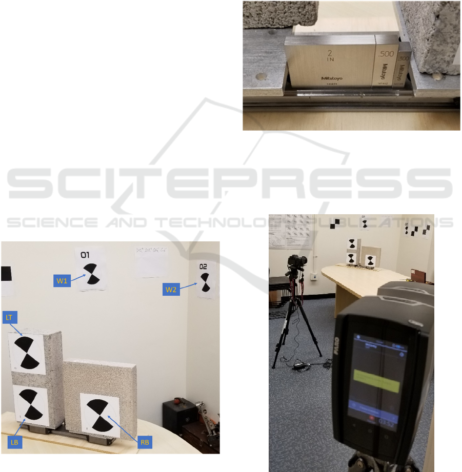
linear bearing system as presented in Figure 1. One of
the blocks was larger in size with overall dimensions
of 394 mm by 197 mm by 89 mm. Two laser scanning
targets (LT and LB) were installed on this block as
shown in Figure 1. The second block was smaller
with overall dimensions of 292 mm by 292 mm by 51
mm. This block had only one laser scanning target
(RB) and the block and the target were used as a
reference. For this purpose, the block was installed on
a fixed carriage of the linear bearing system that did
not move during the experiments.
Figure 1: Setup: two concrete blocks on a linear bearing
system with a few targets.
Two additional fixed laser scanning targets were
used in the study. They were mounted on the wall as
shown in Figure 1 and they were labelled W1 and W2,
respectively.
The tall block was left free to move in respect to
the fixed one, but it was restrained to only move along
the linear bearing system by its attachment to the
movable carriage in the system. The displacements
were imposed in an incremental way by inserting
high-precision blocks (Mitutoyo, 2016) between the
carriages as presented in Figure 2.
Figure 2: Displacement between carriages set by high-
precision blocks.
As shown in Figure 3, the terrestrial laser scanner,
Faro Focus
S
(Faro, 2021), was used to collect point
clouds of both blocks at each displacement.
Figure 3: Terrestrial laser scanner used in the setup.
Comparative Study of Two Approaches for Application of Terrestrial Laser Scanner in Structural Health Monitoring and Damage
Assessment
167
The laser scanner was placed at about 3.8 m away
from the blocks and it was not moved during the
experiment. The scanner was installed at about 45
degrees to the planes of the concrete blocks. It had a
setting of 1/4 resolution and 3x quality (in the scanner
specific options selectable for a scanning process).
The laser scanner was levelled during the scans
ensuring that the vertical axis of all scans coincided
with the true gravitational axis.
3 TWO APPROACHES
Two approaches were evaluated in this study. The
first was based on tracking the centres of laser
scanning targets and the second was based on
monitoring the displacements of the concrete block’s
corner in respect to the corner of the fixed block.
3.1 First Approach
The first approach for tracking the displacements of
the blocks was based on utilization of the laser
scanning targets. In each laser scan the centres of the
targets were estimated by using Cyclone software
from Leica GeoSystems (Leica GeoSystems AG,
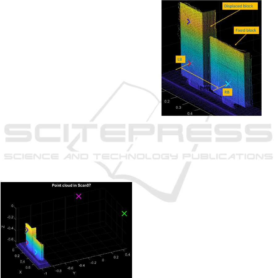
2018). A result showing all the targets for one of the
typical scans is presented in Figure 4. The target
vertices are indicated by crosses. In this paper, the
point clouds are presented in a local coordinate
system ensuring that the X-axis is parallel to the
direction of displacements and the Z-axis is parallel
to the true gravitational vertical axis.
Figure 4: Vertices of laser scanning targets and the point
cloud.
The acquired target centres were exported in
ASCII format and all remaining data reduction was
conducted in the Matlab environment (MathWorks,
2016). Estimates of the distances between the vertices
are presented in Figure 5 for LB to RB targets as a
typical example.
It is worth noting that the point cloud data and the
location of vertices does need to be transformed into
a new coordinate system because the distances
between the vertices are not dependent on a selection
of a coordinate system.
Figure 5: Approach 1: distance between vertices of targets.
This procedure was applied to all five targets in
the study. The targets fixed to the wall were used for
estimation of accuracy of the approach since the
targets were not moving in respect to each other.
This approach was evaluated earlier (Takhirov,
Gilani, and Allen, 2021) for a terrestrial laser scanner
Trimble TX6 (Trimble, 2016) and it was shown to be
an adequate correlation with displacements measured
by accurate position transducers.
3.2 Second Approach
The second approach for tracking the displacements
of the blocks was based on finding a corner of the
moving block at the elevation of the target’s centre,
and tracking its displacement from scan to scan. In
this case, a thin horizontal slice of the point cloud at
the elevation of the target’s centre was analysed as
shown in Figure 6. In this case, the corner of the fixed
block was used as a reference.
A plan view of a typical horizontal slice is shown
in Figure 7. The point cloud corresponding to the
front and the side surfaces of the block are separated
from each other. These subsets of point clouds were
individually best fitted to straight lines by the least
square method. An intersection point of these two
straight lines was considered as a corner of the block.
PHOTOPTICS 2022 - 10th International Conference on Photonics, Optics and Laser Technology
168
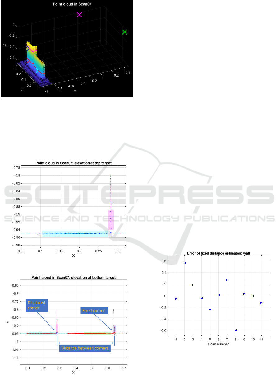
Figure 6: Horizontal slices of point clouds at elevations of
target centres (LB and RB).
To increase the accuracy, the points right next to
the corner were removed to minimize the effects of
the corner’s imperfections. The points in shaded
boxes shown in Figure 7 were used for best fitting to
the straight lines.
Figure 7: Typical result for a corner estimation.
Figure 8: Approach 2: distance between the corners is
estimated.
A corner of the fixed block was estimated in the
same way. The distance between two corners was
estimated as shown in Figure 8 and it was tracked
from scan to scan.
This approach was introduced earlier for the
estimation of residual drifts of columns in a
reconnaissance effort conducted soon after the 2010
Haiti Earthquake (Mosalam, Park, and Takhirov,
2014). This study was conducted by means of a
ScanStation 2 laser scanner (Leica GeoSystems AG,
2007). The application of this approach for the quality
control in construction was recently studied
(Takhirov, 2021). In the latter case, a point cloud
collected by the C10 laser scanner (Leica
GeoSystems AG, 2011) was used.
As mentioned earlier this paper is focused on the
evaluation of both approaches by the Faro Focus
S
laser scanner (Faro, 2021).
4 RESULTS AND DISCUSSION
The approaches described in the previous section of
the paper were compared to each other.
The distance between two targets mounted on the
walls of the laboratory (W1 and W2) must remain the
same. The distances between those targets measured
from the laser scans using the first approach provided
information about its accuracy. A variability of the
estimates of distances between wall-mounted targets
is presented in Figure 9. This variability is shown in
respect to the average of all distances. This result
shows that the variability stays within ±0.6 mm for all
eleven scans.
Figure 9: Variability of estimates of distances between wall
fixed targets (W1 and W2): in respect to the mean.
The distances between the targets mounted on the
movable block (LT and LB) must also remain the
same. The variability of the distance measurements is
Y
E
r
r
o
r
, mm
Comparative Study of Two Approaches for Application of Terrestrial Laser Scanner in Structural Health Monitoring and Damage
Assessment
169
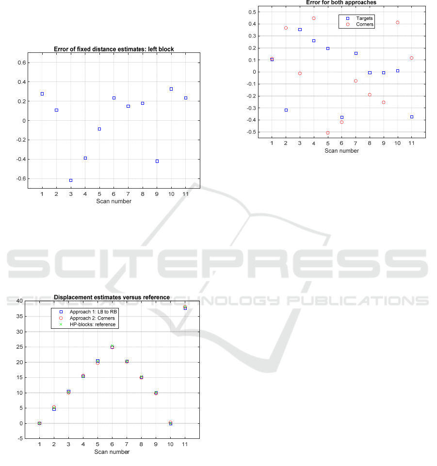
presented in Figure 10. The variability of distances
between those targets is also very close to ±0.6 mm
for all eleven scans. The slight difference between the
two variabilities can be related to the accuracy of the
scanner or the spacing differences in the horizontal
direction (wall-mounted targets) and vertical
direction (left block mounted targets).
Figure 10: Variability of distances between LB and LT: in
respect to the mean.
Figure 11 shows the displacements measured by
both approaches compared to the displacements set
by the high-precision blocks (noted as HP-blocks in
the plot).
Figure 11: Displacement estimates: two approaches.
The error between the two approaches is
presented in Figure 12. As shown in the plot, the error
of the displacement estimate stays within ±0.55 mm.
As shown in Figure 12, both approaches have
about the same sub-millimetre accuracy. The
approach using the laser scanning targets has slightly
better accuracy with the error remaining within a
±0.40 mm range around its average. In the approach
based on tracking corners, the error varies within a
±0.55 mm range around its average.
Figure 12: Errors for two approaches (in respect to the
mean).
5 CONCLUSIONS
The main objective of the paper was to evaluate two
approaches aimed at tracking small displacements.
The first approach is based on tracking displacements
of laser targets commonly used for stitching point
clouds to each other. The second approach is based
on the estimation of corners of thin horizontal slices
of a prismatic shape’s point cloud. The corner’s
location is estimated as an intersection of two straight
lines best fitted to the point clouds beyond the corner.
It was shown that for both approaches a sub-
millimetre accuracy can be achieved. The first
approach requires the installation of two laser targets
to measure the change of the distance between them
but offers slightly better accuracy of ±0.4 mm. The
second approach offers more flexibility because it
does not require the installation of a laser target.
Hence it can be used in the quantitative assessment of
structural damage in aftermath of natural disasters
such as earthquakes, fires, tsunamis, landslides, and
hurricanes, to name a few. Based on the results of this
work, the error of this approach is about ±0.55 mm
greater than that of the first approach.
ACKNOWLEDGEMENTS
Special thanks are due to Faro for providing an access
to the Faro Focus
S
laser scanner. Special thanks are
due to Holly Halligan of UC Berkeley for editing the
paper.
E
r
r
o
r
, mm
X coordinate, mm
E
r
r
o
r
, mm
PHOTOPTICS 2022 - 10th International Conference on Photonics, Optics and Laser Technology
170

REFERENCES
Faro (2021). https://media.faro.com/-/media/Project/
FARO/FARO/FARO/Resources/TechSheet_Focus_La
ser_Scanner/TechSheet_Focus_Laser_Scanner_EN.pd
f?rev=1291d7f5ef814fe99d471dde60321833.
Leica Geosystems AG (2007). https://w3.leica-
geosystems.com/downloads123/hds/hds/ScanStation/b
rochures/LeicaScanStation%202_brochure_en.pdf.
Leica Geosystems AG (2011). Leica ScanStation C10.
http://w3.leica-geosystems.com/downloads123/hds/
hds/ScanStation%20C10/brochures-datasheet/Leica_
ScanStation_C10_DS_us.pdf.
Leica Geosystems AG (2018). Cyclone Version 9.2.1.
MathWorks (2016). Matlab Version R2016b.
Mitutoyo (2016). https://www.mitutoyo.com/wp-content/
uploads/2016/09/E-section-Gage-Blocks.pdf last
retrieved on 11/23/20.
Mosalam, K.M., Takhirov, S.M., and Park, S. (2014).
Applications of Laser Scanning to Structures in
Laboratory Tests and Field Surveys. Journal of
Structural Control and Health Monitoring, Volume 21,
Issue 1, pages 115–134, January 2014.
Takhirov, S.M. (2009). Video, Still, and Laser Imaging
at nees@berkeley: Case Studies, Presentation at
Bi-annual Hybrd Simulation Workshop, August 2009.
Takhirov, S.M., and Mosalam K.M. (2014). Applications of
Laser Scanning to Structural Testing and Field Survey
in Earthquake Engineering. 10th US National
Conference on Earthquake Engineering, Frontiers of
Earthquake Engineering, Quake Summit 2012, July 21-
25, 2014, Anchorage, Alaska.
Takhirov, S.M., Gilani, A., and Allen, J. (2020).
Experimental Evaluation of Novel On-Demand and
Smart Real-Time Structural Monitoring of Buckling
Restrained Brace’s Deformation with Laser Scanners.
EWSHM2020. The 10th European Workshop on
Structural Health Monitoring. Palermo, Italy, July 6-9,
2020.
Takhirov, S.M. (2021). Control of Construction Quality by
a Terrestrial Laser Scanner: Example of Steel Frame
Building. HORA-2021, the 3rd International Congress
on Human-Computer Interaction, Optimization and
Robotic Applications, June 11-13, 2021, Turkey.
Takhirov, S.M., Gilani, A., and Allen, J. (2021).
Comparative Evaluation of Laser Scanning and Image
Tracking for Deformation Monitoring of Buckling
Restrained Brace. 10th International Conference on
Structural Health Monitoring of Intelligent
Infrastructure. 30 June - 2 July, 2021, Porto, Portugal.
Trimble Inc (2016). The Trimble TX6 laser scanner.
http://trl.trimble.com/docus hare/dsweb /Get/Docum
ent-82496 5/022516-282_Trimb leTX6 DS_US_10
16_LR.pdf. Accessed 3 Jan 2020.
Comparative Study of Two Approaches for Application of Terrestrial Laser Scanner in Structural Health Monitoring and Damage
Assessment
171
