Acousto-optic k-space Filtering of Optical Beams
Konstantin B. Yushkov
a
National University of Science and Technology “MISIS”, 4 Leninsky Prospekt, Moscow 119049, Russia
Keywords:
Acousto-optics, Tunable Filter, Spatial Filter, Phase Imaging, Optical Trapping.
Abstract:
Acousto-optic tunable filters (AOTFs) can be used for spatial filtering of optical beams. A noncollinear AOTF
has a tunable ring-shaped transfer function determined by geometry of the refractive index surface in a uniaxial
crystal. Different axially symmetric transfer functions can be synthesized using multi-frequency ultrasonic
signals. In the report, theory of AOTF-based spatial filtering of optical beams is summarized. Specific transfer
function of the AOTF — bandpass spatial frequency filter — enables hyperspectal phase imaging in dark-field
mode using incoherent illumination. Operation of a dynamic ring-shaped optical trap based on the noncollinear
AOTF is demonstrated.
1 INTRODUCTION
Acousto-optic tunable filters (AOTF) find broad ap-
plications as hyperspectral imaging devices (wide-
aperture monochromators and programmable multi-
window filters) in the fields of biophotonics, remote
sensing, and space research (Lu and Fei, 2014; Ko-
rablev et al., 2018; Genchi et al., 2021). Besides that,
AOTFs are also capable of tunable spatial filtering of
optical beams. This feature has been known since
1980-ies (Balakshy, 1984), but only a few of its appli-
cations in Optics, Photonics, and Laser Physics have
been reported until recently (Balakshy and Voloshi-
nov, 2005; Balakshy and Kostyuk, 2009). In this re-
port, fundamentals and novel applications of AOTF-
based optical beam shaping are observed.
Anisotropic acousto-optic diffraction in Bragg
regime is used in AOTFs. It is a tree-wave mixing
linear optical interaction, which is governed by the
phase matching condition. Ultrasonic wave produces
periodic modulation of refractive index in an interac-
tion medium — a volume phase grating to which a
reciprocal grating vector can be assigned. Efficient in-
teraction is only possible if momentum of interacting
waves is conserved. Thus, Bragg phase matching de-
termines wavelength and angular selectivity that en-
ables design of tunable optical filters. Interaction of
finite-size optical beams is analyzed using plane wave
decomposition. As the result, the acousto-optic fil-
ter can operate as a tunable k-space filter of optical
beams.
a
https://orcid.org/0000-0001-9015-799X
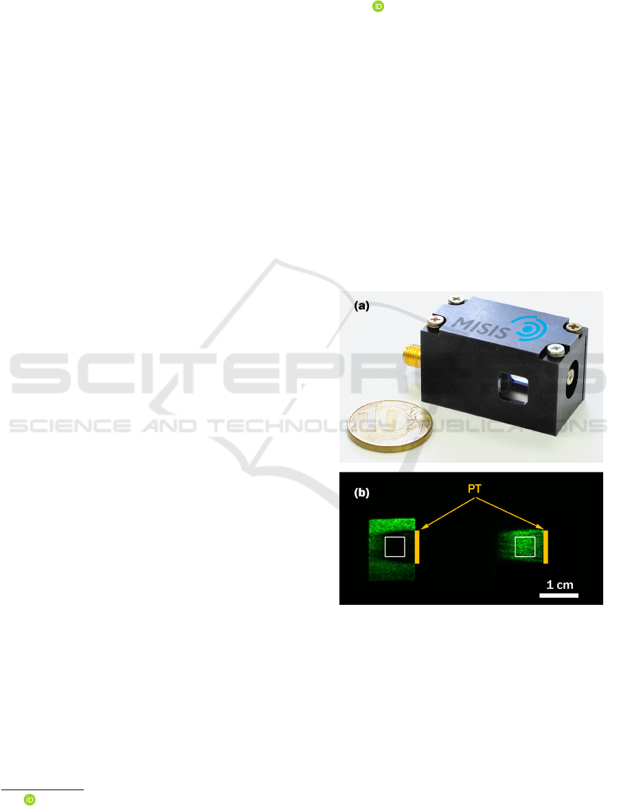
Figure 1: Noncollinear paratellurite AOTF: (a) real-size
photograph; (b) acoustic field visualization: left — 0
th
or-
der; right — 1
st
order; white rectangle — optical aperture;
yellow rectangle — piezotransducer (PT).
A paratellurite (TeO
2
) single crystal AOTF de-
signed and fabricated in-house (NUST “MISIS”) is
shown in Fig. 1 (a). There are two beams at the AOTF
output: the 0
th
and the 1
st
diffraction orders, Fig. 1 (b).
The AOTF demonstrates diffraction efficiency over
98% in the optical aperture area (5 × 5 mm
2
) and ho-
mogeneity of the diffracted field intensity within 15%
r.m.s.
Yushkov, K.
Acousto-optic k-space Filtering of Optical Beams.
DOI: 10.5220/0010972700003121
In Proceedings of the 10th International Conference on Photonics, Optics and Laser Technology (PHOTOPTICS 2022), pages 69-75
ISBN: 978-989-758-554-8; ISSN: 2184-4364
Copyright
c
2022 by SCITEPRESS – Science and Technology Publications, Lda. All rights reserved
69
2 FUNDAMENTALS
2.1 AOTF Transfer Function
The transfer function of a linear space-invariant op-
tical system is defined as a transmission coefficient
of the angular spectrum (Goodman, 2005). The
first-order transmission coefficient of a Bragg grating
is derived from plane-wave coupling-of-modes the-
ory (Yariv and Yeh, 1984):
H
ao
(k
x
,k
y
;F) =
Q
p
Q
2
+ R
2
(k
x
,k
y
;F)
×
sin
π
2
q
Q
2
+ R
2
(k
x
,k
y
;F), (1)
where Q is the coupling coefficient and R(k
x
,k
y
;F)
is the phase mismatch depending transverse compo-
nents of the wave vector k
x
and k
y
and ultrasound fre-
quency F provided optical frequency λ is given.
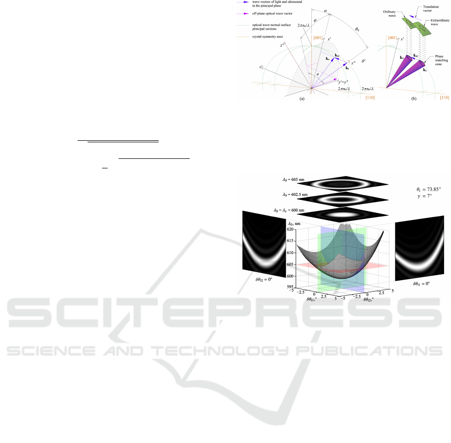
The mismatch R(k
x
,k
y
;F) is calculated from a 3D
wave vector diagram, see Fig. 2. AOTFs are designed
in uniaxial crystals using their birefringence. To ob-
tain wide acceptance angle, which is necessary for
image processing, noncritical phase matching (NPM)
geometry is chosen. Angular bandwidth of NPM is
directly related to curvature of the optical wave nor-
mal surface in the crystal (Yushkov, 2021; Yushkov
and Naumenko, 2021). It follows from differential ge-
ometry of wave normal surfaces that two fundamental
topologies of phase matching in the neighborhood of
NPM points are elliptical and hyperbolic. The NPM
frequency F
npm
is a local minimum of F(k
x
,k
y
) for the
elliptical topology and the saddle point for the hyper-
bolic one. Topological transition between these ge-
ometries takes place only at certain direction of ultra-
sound, which are determined only by principal values
of dielectric permittivity tensor (Yushkov and Nau-
menko, 2021). The vector diagram in Fig. 2 illustrates
conical phase matching in a positive uniaxial crystal.
Explicit expression for R(k
x
,k
y
;F) in a non-
collinear acousto-optic diffraction geometry in uniax-
ial crystals can be found elsewhere (Yushkov et al.,
2020a; Yushkov et al., 2020b). Figure 3 shows a
typical phase matching surface in k-space (k
x
∝ δθ
i2
,
k
y
∝ δθ
i1
).
Intensity transfer function
T
1
(k
x
,k
y
) = |H
ao
(k
x
,k
y
)|
2
(2)
can be readily visualized in experiment. The setup for
transfer function visualization is schematically shown
in Fig. 4 (a). A collimated laser beam is focused onto
an AOTF. An output polarizer is used to select one
of the diffraction orders. The output beam is cap-
tured from a screen with a CCD. Experiment in Figs 4
Figure 2: 3D wave vector diagram of anisotropic Bragg
diffraction: (a) definition of angular coordinates for off-
axial diffraction in a uniaxial crystal; (b) conical phase
matching in the neighborhood of the noncritical phase
matching geometry. Reproduced under Open Access Li-
cence from (Yushkov et al., 2020a),
c
2020 OSA.
Figure 3: Zero phase mismatch surface: the case of non-
collinear AOTF. Reproduced under Open Access Licence
from (Gorevoy et al., 2021),
c
2021 OSA.
(b)-(d) shows the transfer function T
1
measured ex-
perimentally. Paratellurite AOTF with acoustic beam
orientation α = 9.06
◦
and λ = 532 nm laser were
used, the transfer functions were measured at RF sig-
nal frequencies of 132.4, 133.0, and 133.6 MHz. The
first result is a low-pass angular frequency filter with
maximum transmission at k
x
= k
y
= 0 at F ≈ F
npm
=
132.4 MHz. The other results demonstrate a tunable
bandpass filter with almost circular phase matching
locus k
2
x
+ k
2
y
= ρ
2
(F) with ρ
2
∝ (F − F
npm
). Simula-
tions show that at low paratellurite crystal cut angles
(α . 12
◦
) the transfer function asymmetry manifests
itself mainly as the shift of the transfer function cen-
ter (Yushkov et al., 2020b).
2.2 Optical System Layouts
Two common optical schemes for AOTF-based opti-
cal beam shaping systems are shown in 5: the confo-
cal one and the Fourier-transform one. For simplicity,
both optical schemes in Fig. 5 are shown with unity
scaling factors and equal focal lengths f of front-end
and back-end optics. A general case of arbitrary focal
lengths can be analyzed in the same way. Beam stops
PHOTOPTICS 2022 - 10th International Conference on Photonics, Optics and Laser Technology
70
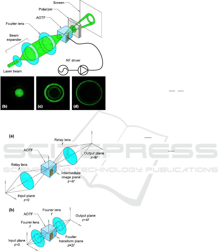
Figure 4: Visualization of AOTF transfer function: (a) ex-
periment scheme; (b)-(d) first-order AOTF transfer func-
tions measured at different signal frequencies.
Figure 5: Two principal layouts of AOTF-based spatial fil-
tering schemes: (a) confocal scheme; (b) Fourier-transform
scheme.
to separate the diffraction orders are assumed but not
plotted.
The confocal system shown in Fig. 5 (a) performs
direct k-space filtering of the optical beam:
A
out
(k
x
,k
y
) = H
ao
(k
x
,k
y
)A
in
(k
x
,k
y
). (3)
In this scheme, the input field U
in
(x,y) is relayed to
the AO interaction plane and its angular spectrum is
unaltered. The diffracted field has the angular spec-
trum modified according to Eq. (3).
The confocal optical scheme is typical for low-
aberration hyperspectral imaging systems (Suhre
et al., 2004). Annular transfer function of the AOTF
enables application of this scheme for hyperspectral
imaging in dark field mode. Application of this new
imaging modality for phase imaging is discussed in
Sec. 3.1.
The Fourier-transform optical scheme shown in
Fig. 5 (b). In this scheme, the AOTF transfer func-
tion is a complex-valued multiplier in the output field
distribution:
U
out
(x,y) = H
ao
x
λ f
,
y
λ f
U
in
(x,y) (4)
where the scaling factor between k-space and coor-
dinate space (x,y) is λ f : x/(λ f ) = k
x
and y/(λ f ) =
k
y
. Derivation of Eq. (4) simply follows from prop-
erties of optical Fourier transform performed by a
lens (Goodman, 2005):
U
fp
(x,y) =
1
iλ f
ZZ
+∞
−∞
U
in
(x
0
,y
0
)×
exp
−
2πi
λ f
(xx
0
+ yy
0
)
dx
0
dy
0
(5)
is the optical field at the Fourier plane z = 2 f (i.e., at
the AOTF input), and
A
fp
(k
x
,k
y
) = −iλ fU
in
(−λ f k
x
,−λ f k
y
) (6)
is its plane wave spectrum. Equation (4) explicitly
follows from applying the optical Fourier transform
twice.
Fourier-transform scheme is an effective solution
for laser beam shaping. Dynamic annular optical trap
based on this principle is described in Sec. 3.2.
2.3 Laser Beam Shaping
Laser beam shaping is a new branch in acousto-optic
instrumentation, which broadens the range of applied
problems in science and engineering solved with the
usage of the effect of light diffraction by ultrasound
(Yushkov et al., 2018). In can extend operation rates
of current beam shaping methods (Dickey, 2014) up
to 100 kHz owing to fast response of AOTFs and other
acousto-optic devices.
Transfer function analysis in Sec. 2.1 was made
under assumption of single-frequency RF signals re-
sulting in a periodic phase grating with unique grat-
ing vector k
ac
. A straightforward way to synthesize
transfer functions with variable transmission width is
Acousto-optic k-space Filtering of Optical Beams
71

to apply multifrequency RF signals. Each monochro-
matic component of ultrasound will provide phase
matching at its own locus of spatial frequencies re-
sulting in broadening of the transfer function or gen-
eration of multiple independent rings. Acoustic time
aperture of the AOTF, τ
ac
, is the minimum time re-
quired to change transfer function. The time aperture
is reciprocal to RF phase matching bandwidth δF.
In order to provide controllable phase relations be-
tween components of the RF signal, one can use dis-
persive waveform synthesis (Yushkov et al., 2019b).
The ultrasonic signal S(t) is calculated as the Fresnel
transform (i.e., Fourier transform with quadratic spec-
tral phase factor) of the transmission window function
W (F
k
):
S(t) =
1
K
K
∑
k=1
W (F
k
)exp
πiF
2
k
τ
ac
∆F
×
exp(−2πiF
k
t), (7)
where ∆F is the effective FWHM signal bandwidth;
the number of sampling points is determined from the
Nyqist criterion, K = 2∆Fτ
ac
; and the frequency grid
centered at the frequency F
c
is
F
k
= ∆F
2k − K − 1
K − 1
+ F
c
. (8)
Equation (7) was derived to comply with the period-
icity property of discrete Fourier transform. The cen-
tral frequency F
c
can be chosen arbitrarily that allows
continuous tuning of the transmitted interval of spatial
frequencies.
The signal S(t) is sampled and synthesized using
an RF arbitrary waveform generator (AWG). In eq. (7)
it was assumed that two conditions are met to provide
stationary AOTF transmission with minimized distor-
tions:
1. RF signal period equals the AOTF time aperture
τ
ac
;
2. the transmission window satisfies the uncer-
tainty relation for chirped pulses (Yushkov et al.,
2021b).
The dispersive waveform synthesis method enables
such output modes as flat-top laser beam shaping and
generation of bottle laser beams with variable diam-
eter and wall thickness (Yushkov et al., 2021a). The
examples of Gaussian laser beam shaping are shown
in Fig. 6. Panels (a) and (c) were obtained with single-
frequency RF signals corresponding to Fig. 4; panels
(b) and (d) were obtained with multi-frequency RF
signals synthesized according to (7).
Figure 6: Laser beam shaping with a noncollinear AOTF:
(a) low-pass spatial filtering; (b) flat-top beam shaping; (c)
band-pass spatial filtering; (d) bottle beam shaping. Repro-
duced from (Yushkov et al., 2021a),
c
2021 SPIE–OSA.
Figure 7: Experimental setup for hyperspectral phase imag-
ing based on AOTF operation in dark-field mode: red ar-
rows — optical path. Reproduced under Open Access Li-
cence from (Yushkov et al., 2020a),
c
2020 OSA.
3 APPLICATIONS OVERVIEW
3.1 Phase Imaging
Angular selectivity of acousto-optic Bragg diffraction
can be used for physical-level phase imaging. For ex-
ample, it has been previously shown that differential
phase imaging can be obtained with gradient transfer
functions of an AOTF (Balakshy and Kostyuk, 2009;
Balakshy, 2018).
The confocal AOTF scheme, Fig. 5, can process
optical images in dark field mode that enables phase
imaging. Coherent phase imaging system is a bright-
field light microscope with narrowband object illumi-
nation and a confocal hyperspectral imaging system
placed at the microscope output optical port (Yushkov
et al., 2016). Changing the frequency of ultrasound,
one can select the spatial frequency transmitted by
the AOTF and therefore to change object visualiza-
tion mode.
Phase imaging with broadband incoherent illumi-
nation requires a system modification since differ-
ent wavelength of the input light will be efficiently
diffracted at different spatial frequencies. When a
plane wave passes through a phase object its an-
gular spectrum is broadened because of scattering.
Lower spatial frequencies of the optical beam are
blocked by a spatial light modulator (SLM) placed
PHOTOPTICS 2022 - 10th International Conference on Photonics, Optics and Laser Technology
72
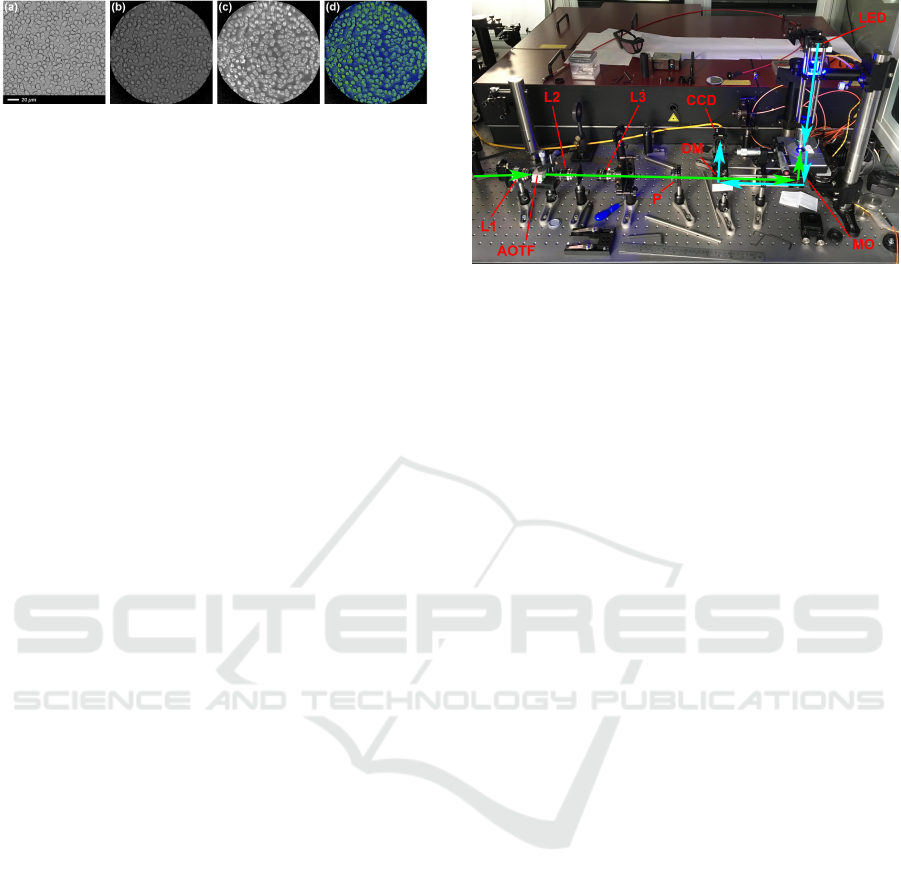
Figure 8: Demonstration of acousto-optic phase imaging:
(a) reference image captured with an RGB camera; (b)
bright-field spectral image; (c) dark-field phase image; (d)
false-color fusion of amplitude-and-phase modulation. Re-
produced under Open Access Licence from (Yushkov et al.,
2020a),
c
2020 OSA.
in a Fourier-conjugated plane of the system (Yushkov
et al., 2019a; Yushkov et al., 2020a). Higher spatial
frequencies that contain only the scattered light are
transmitted to satisfy dark field phase imaging prin-
ciple. Then the conical beam is spectrally filtered by
the AOTF. According to the phase matching surface
symmetry, all components of the conical beam are
diffracted by the AOTF within the same wavelength
window. Matched spectral and spatial filtering results
in high resolution wide-field phase imaging.
When the spatial light modulator is switched off,
the AOTF operates in a regular bright-field spectral
imaging mode. That allows correct calibration of
phase imaging and false-color fusion of phase-and-
amplitude modulation. An example of phase imaging
is shown in Fig. 8.
3.2 Optical Trapping
The phenomenon of optical trapping has been known
for four decades (Ashkin, 1992). The range of appli-
cation of optical traps and tweezers covers many dis-
ciplines ranging from microbiology to manipulation
of cold atoms. The technology of optical traps is con-
stantly being improved, and recently a need has arisen
for dynamical generation of various geometrical con-
figurations of optical traps, which requires advanced
methods of laser beam shaping. One of such meth-
ods is a noncollinear AOTF based laser beam shap-
ing. The use of several frequencies to feed the AOTF
makes it possible to synthesize various radial field dis-
tributions and to tune them with sub-10-µs response
time.
Experimental setup of a ring-shaped optical trap
is shown in Fig. 9 (Obydennov et al., 2021a; Oby-
dennov et al., 2021b). The optical scheme is a modi-
fied Fourier-transform scheme, Fig. 5 (b), with an ad-
ditional relay lens group between the AOTF and the
second Fourier lens. The relay optics performs laser
beam magnification and transport from the AOTF to
the back focal plane of a microscope objective, which
is the second Fourier lens. Thus, the angular aper-
ture of the AOTF was matched with the aperture of
Figure 9: Optical trapping setup based on a noncollinear
AOTF: CCD — imaging camera; DM — long-pass dichroic
mirror; L1, L2, L3 — lenses; LED — light emitting diode
for illumination; MO — microscope objective; P — thin-
film polarizer; green arrows — laser beam path at 532 nm;
cyan arrows — illumination path at 460 nm.
the objective. Laser radiation with the wavelength of
532 nm was used. Passing through the expander, the
laser beam was focused by means of a Fourier lens
into the volume of a noncollinear paratellurite AOTF
specially optimized and fabricated for this work. The
operating frequency of the filter in the wide-aperture
diffraction geometry is 132.35 MHz, the bandwidth
is 0.24 MHz. The 0
th
diffraction order at the AOTF
output was blocked by a thin-film polarizer. The ob-
jective converted the ring-shaped angular spectrum of
the beam into spatial intensity distribution, which ex-
poses the sample.
The sample was a suspension of polystyrene mi-
crospheres with an average diameter of 10 µm. The
liquid phase of the suspension was deionized water
with the addition of a liquid antiseptic and a surfactant
to prevent adhesion. The suspension was placed in a
special reaction cell made of cover glass. To visualize
the sample, we used a transmission K
¨
ohler illumina-
tion system with a blue diode light source. Passing
through the sample, the radiation was collected by an
objective and imaged onto on the CCD matrix through
a dichroic mirror and a tube lens.
Demonstration of the annular trap operation is
shown in Fig. 10. The radius of the trapping ring was
controlled by changing the RF signal frequency in the
range from 132.4 to 134.0 MHz. A programmable
AWG was used for this purpose. Panel (a) shows
opration of the trap in a static mode, the radius of the
ring being fixed. In this particular example, the mi-
crospheres are arranged in a circle with the radius of
80 µm at F = 134.0 MHz. A dynamic trap is shown
in panels (b) and (c): the RF signal had sawtooth fre-
quency sweep resulting in generation of a series of
convergent or divergent trapping rings. As the result,
the microspheres were either aggregated in the center
of the trap or repulsed from the center.
Acousto-optic k-space Filtering of Optical Beams
73
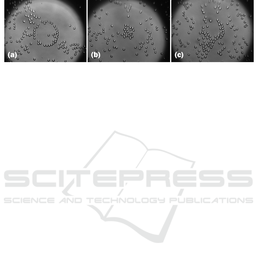
Figure 10: Optical trapping demonstration: (a) static single-ring trap; (b) aggregation of particles by dynamic converging-ring
trap; (c) disaggregation of particles by dynamic diverging-ring trap.
4 DISCUSSION
Diffraction efficiency of an AOTF is one of the key
performance parameters in applications. According
to Eq. 1, for a plane wave component without mis-
match max H
ao
= 1 when Q = 1 and R(k
x
,k
y
;F) = 0.
In practice, the efficiency can be rather close to 1.
Visualization of the 0
th
diffraction order in Fig. 1
demonstrates overall efficiency above 98% within the
whole active aperture of the AOTF. Thus, overall op-
tical losses in the AOTF including Fresnel reflections
can be well below 5% for linearly polarized light.
In optical beam shaping applications described in
Sec. 3 the beams are spatially filtered by the AOTF,
thereby the overall throughput is an integral of the op-
tical beam angular spectrum multiplied by the trans-
fer function H
ao
. In the case of phase imaging, the
optical beam is pre-filtered by the dark-field Fourier-
plane filter implemented on the SLM. Therefore an-
gular spectrum of the beam is already matched with
the annular AOTF transfer function and the polariza-
tion at the SLM output is linear as required for the
AOTF. In the case of annular optical trap, a Gaussian
input beam was used at the AOTF input. For this rea-
son, lower spatial frequencies of the beam were not
used and the diffracted beam intensity was few per-
cent of the input beam even though the diffraction effi-
ciency for phase-matched components of the angular
spectrum was above 95%. Optimization of the sys-
tem throughput by means of refractive flat-top beam
shaping (Laskin et al., 2011; Dickey, 2014) before the
AOTF will be a plot for future work.
Another potential advancement in AOTF-based
laser beam shaping is related to using biaxial crys-
tals. The topology of the transfer function depends
on local curvature of the optical wave normal surface
in the phase matching region of the k-space (Yushkov
and Naumenko, 2021). In a uniaxial crystal, there are
only three types on the NPM transfer function, one
of them being the annular transfer function discussed
in this work. In biaxial crystals, the geometry of the
wave normal surface is more complicated, and other
topologies of the transfer function may exist enabling
asymmetrical transfer functions, one dimensional tun-
able k-space filtering, and high-order NPM geome-
tries.
ACKNOWLEDGEMENTS
The author thanks contributions to this work from the
Acousto-Optical Research Center team.
The research was supported by the Russian Sci-
ence Foundation (RSF) under project 21-12-00247.
REFERENCES
Ashkin, A. (1992). Forces of a single-beam gradient laser
trap on a dielectric sphere in the ray optics regime.
Biophys. J., 61(2):569–582.
Balakshy, V. (1984). Acoustooptical cell as the space fre-
quency filter. Sov. J. Commun. Technol. Electron.,
29(8):1610–1616.
Balakshy, V. (2018). Acousto-optic visualization of optical
wavefronts. Appl. Opt., 57(10):C56.
Balakshy, V. and Kostyuk, D. (2009). Acousto-optic image
processing. Appl. Opt., 48(7):C24.
Balakshy, V. and Voloshinov, V. (2005). Acousto-optic im-
age processing in coherent light. Quantum Electron.,
35(1):85–90.
Dickey, F., editor (2014). Laser Beam Shaping: Theory and
Techniques. CRC Press, Boca Raton, FL, 2nd edition.
Genchi, L., Bucci, A., Laptenok, S., Giammona, A., and
Liberale, C. (2021). Hadamard-transform spectral
acquisition with an acousto-optic tunable filter in a
broadband stimulated raman scattering microscope.
Opt. Express, 29(2):2378–2386.
Goodman, J. (2005). Introduction to Fourier Optics.
Roberts, New York, 3rd edition.
Gorevoy, A., Machikhin, A., Martynov, G., and Pozhar,
V. (2021). Spatiospectral transformation of noncol-
PHOTOPTICS 2022 - 10th International Conference on Photonics, Optics and Laser Technology
74

limated light beams diffracted by ultrasound in bire-
fringent crystals. Photonics Res., 9(5):687.
Korablev, O., Belyaev, D., Dobrolenskiy, Y., Trokhi-
movskiy, A., and Kalinnikov, Y. (2018). Acousto-
optic tunable filter spectrometers in space missions.
Appl. Opt., 57(10):C103–C119.
Laskin, A., Shcherbakov, A., Molchanov, V., Laskin, V.,
and Makarov, O. (2011). Developing the refractive
light beam shapers as lossless apodization systems
suppressing the side-lobes in Fourier transform opti-
cal systems. Proc. SPIE, 8011:80110L.
Lu, G. and Fei, B. (2014). Medical hyperspectral imaging:
a review. J. Biomed. Opt., 19(1):010901.
Obydennov, D., Yushkov, K., and Molchanov, V. (2021a).
Acousto-optic annular beam shaping for optical traps
and lattices. Proc. SPIE, 11926:1192610.
Obydennov, D., Yushkov, K., and Molchanov, V. (2021b).
Ring-shaped optical trap based on acousto-optic tun-
able spatial filter. Opt. Lett., 46(18):4494.
Suhre, D., Denes, L., and Gupta, N. (2004). Telecentric
confocal optics for aberration correction of acousto-
optic tunable filters. Appl. Opt., 43(6):1255–1260.
Yariv, A. and Yeh, P. (1984). Optical Waves in Crystals.
Wiley, New York.
Yushkov, K. (2021). Noncritical acousto-optic Bragg phase
matching: Analysis of orthorhombic and monoclinic
crystal systems. Appl. Opt., 60(24):7113.
Yushkov, K., Champagne, J., Kastelik, J.-C., Makarov, O.,
and Molchanov, V. (2020a). AOTF-based hyperspec-
tral imaging phase microscopy. Biomed. Opt. Express,
11(12):7053.
Yushkov, K., Champagne, J., Kastelik, J.-C., and
Molchanov, V. (2019a). Hyperspectral phase imaging
with a spatially matched acousto-optical tunable filter.
Proc. SPIE, 10890:108900V.
Yushkov, K., Chizhikov, A., Makarov, O., and Molchanov,
V. (2020b). Optimization of noncollinear AOTF de-
sign for laser beam shaping. Appl. Opt., 59(27):8575.
Yushkov, K., Gurov, V., and Molchanov, V. (2021a). En-
gineering of aotf transfer function for phase imaging
microscopy and optical trapping. In European Confer-
ences on Biomedical Optics 2021 (ECBO), OSA Tech-
nical Digest, page ETu3B.5, Munchen, Germany. Op-
tical Society of America.
Yushkov, K., Makarov, O., and Molchanov, V. (2019b).
Novel protocol of hyperspectral data acquisition by
means of an acousto-optical tunable filter with synthe-
sized transmission function. Opt. Lett., 44(6):1500.
Yushkov, K., Molchanov, V., Balakshy, V., and Mant-
sevich, S. (2018). Acousto-optical transfer func-
tions as applied to laser beam shaping. Proc. SPIE,
10744:107440Q.
Yushkov, K., Molchanov, V., Belousov, P., and Abrosi-
mov, A. (2016). Contrast enhancement in microscopy
of human thyroid tumors by means of acousto-
optic adaptive spatial filtering. J. Biomed. Opt.,
21(1):016003.
Yushkov, K., Molchanov, V., and Khazanov, E. (2021b).
Uncertainty relation in broadband laser pulse shaping.
Phys. Uspekhi, 64(8):828.
Yushkov, K. and Naumenko, N. (2021). Optical beam
diffraction tensor in birefringent crystals. J. Opt.,
60(9):095602.
Acousto-optic k-space Filtering of Optical Beams
75
