
Development of a Piezoelectric Micromachined Ultrasound
Transducer using Microfabrication Technology for in Vitro
Neuromodulation
Ryo Furukawa
a
and Takashi Tateno
b
Bioengineering and Bioinformatics, Graduate School of Information Science and Technology, Hokkaido University,
Kita 14, Nishi 9, Kita-ku, Sapporo, Hokkaido 060-0814, Japan
Keywords: Numerical Calculations, Microfabrication, Neuromodulation, Piezoelectric Micromachined Ultrasound
Transducer, Ultrasound Brain Stimulation.
Abstract: Ultrasound neuromodulation, in which local and deep areas of the brain are stimulated, is promising for
clinical applications. However, the mechanisms of action underlying the stimulation are still unknown. To
elucidate the induction mechanisms, in vitro experiments are useful because they allow the extracellular
conditions to be easily controlled. In this study, we developed a piezoelectric micromachined ultrasound
transducer (PMUT) to modulate the activity of brain slices at the micrometer scale. To examine the
relationship between the transducer size and the resonant frequency of the voltage-driven oscillations, we
modeled the multi-layered structure and performed numerical calculations. A simple mathematical expression
to estimate the size of the PMUT was obtained. We also designed and fabricated a PMUT with identical
circular diaphragms with 580-μm radius. In addition, recording microelectrodes were fabricated into the
PMUTs to monitor the transducer-driven neural activity. To characterize the PMUT properties, including the
intensity and resonant frequency, we measured the pressure oscillations of the transducer driven by the applied
sinusoidal voltage. Finally, we discuss the possibility of using our PMUT to stimulate brain slices in future
applications.
1 INTRODUCTION
Neuromodulation techniques have been studied as
promising tools for the treatment of brain diseases
(Bewernick et al., 2010). Because the intensity of
electromagnetic waves attenuates with increasing
distance, noninvasively inducing transcranial neural
responses in deep brain regions is difficult using
conventional methods, such as transcranial direct
current and magnetic stimulation methods (Wagner et
al., 2007). Overcoming this limitation, transcranial
ultrasound stimulation has recently drawn attention
owing to its low- or non-invasiveness and higher
spatial resolution (Tufail et al., 2010).
Neural impulses have historically been considered
to be electrical signals; the suprathreshold
depolarization of neural membranes was also
influenced by mechanical mechanisms. Thus,
a
https://orcid.org/0000-0001-8920-1025
b
https://orcid.org/0000-0001-9429-9880
describing a neural impulse via a mechanical pathway
could support a physical basis for ultrasound-driven
neuromodulation. However, its underlying
mechanisms at the cellular level are still unknown. A
reason for this is the lack of an in vitro method for
stimulating local circuits in the brain with this
technology at high spatial resolution. In addition,
indirect neural activity through polysynaptic
pathways could affect the neuromodulation, which
further complicates the investigation of the
mechanism of action (Sato et al., 2018). conventional
ultrasound transducers are of limited use for brain
stimulation because they are too large (>10 mm) to
locally stimulate neurons on a spatial scale of tens to
hundreds of micrometers.
Microelectromechanical system (MEMS)
technology has recently been used to produce a
transducer for ultrasound brain stimulation. For
example, Kim et al. developed a capacitive
196
Furukawa, R. and Tateno, T.
Development of a Piezoelectric Micromachined Ultrasound Transducer using Microfabrication Technology for in Vitro Neuromodulation.
DOI: 10.5220/0010938500003123
In Proceedings of the 15th International Joint Conference on Biomedical Engineering Systems and Technologies (BIOSTEC 2022) - Volume 1: BIODEVICES, pages 196-203
ISBN: 978-989-758-552-4; ISSN: 2184-4305
Copyright
c
2022 by SCITEPRESS – Science and Technology Publications, Lda. All rights reserved
micromachined ultrasound transducer (CMUT) and
conducted an in vivo experiment to stimulate the
brain of a freely moving mouse (Kim et al., 2019) ;
their CMUT stimulated the brain regions on a scale of
2.8 mm. In addition, Lee et al. developed a
piezoelectric micromachined ultrasound transducer
(PMUT) and demonstrated its effectiveness for
elucidating the cellular mechanisms of
neuromodulation in cultured neural networks in vitro
(Lee et al., 2019). However, in their experiments with
cultured brain cells, because neurons in the neural
tissue were isolated and rewired in cultured networks,
the original neural networks were rebuilt in networks
with a random connection.
For a given energy input, PMUTs are more
effective than CMUTs in driving micrometer-sized
ultrasound transducers (Manwar et al., 2020).
Therefore, we used PMUTs in this study. We
examined how the device structure influences the
resonant frequency and the intensity of the generated
ultrasound. In addition, we propose that an in vitro
experimental system is useful for examining the
cellular mechanisms of ultrasound neuromodulation
because it allows the extracellular conditions of the
targeted neurons to be easily controlled.
We first examined the relationships among the
multi-layered PMUT structure, the size of the
diaphragms in the transducer, and the resonant
frequency of the transducer. Each of the diaphragms
was designed to resonate at 500 kHz for neural
stimulation. A physical model of the PMUT was
constructed. The relationships among the PMUT
properties were analytically calculated using this
model and the physical parameters of the PMUT
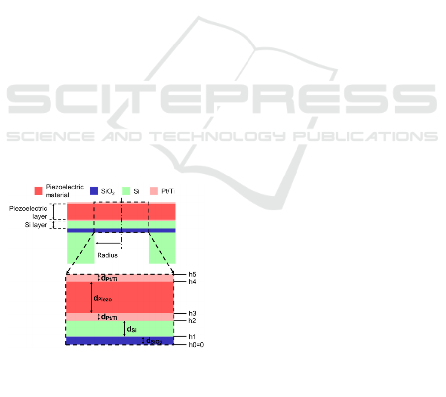
Figure 1: Cross-section of the PMUT, which consisted of
piezoelecctric material, Si, SiO
2
, and Pt/Ti layers. The
expanded view of the top pannel (dashed square) is shown
in the bottom panel. The layer thicknesses are indicated by
arrows, which are considered in Eqs (5) and (7).
materials. In addition, the result of the analytical
calculation was compared with that of numerical
simulations using multiphysics software. We then
designed a PMUT and circular diaphragms as
microelectrodes to simultaneously record the neural
activity in a brain slice under ultrasound stimulation.
Because the ultrasound-driven response is strongly
dependent on the background activity of neural
circuits, we consider that PMUT devices equipped
with recording electrodes are more appropriate than
conventional methods without recording functions
for neural stimulation. To characterize the PMUT
properties, including the intensity and resonant
frequency, we measured the pressure oscillations of
the transducer driven by the applied sinusoidal
voltage. Finally, we examine whether our PMUT has
the potential to effectively stimulate local networks in
brain slices in future studies.
2 METHODS
To locally stimulate brain slices, we aimed to develop
a PMUT that satisfies three numerical conditions: (i)
a resonant frequency of the diaphragm of 500 kHz,
(ii) an ultrasound intensity for stimulation greater
than 0.5 W/cm
2
, and (iii) a diaphragm radius smaller
than 0.6 mm (Lee et al., 2019).
2.1 The PMUT Model and Numerical
Calculations
Our PMUT consisted of the following five
components: a piezoelectric film, a silicon (Si) layer,
a SiO
2
membrane, top and bottom Pt/Ti electrodes,
and a Si supporting layer (Fig. 1). To convert electric
(voltage) signals into ultrasound pressures, a thin film
of a piezoelectric material was used as the transducer.
To achieve a thin diaphragm as a vibrating plate,
circular drains were designed from the back side of
the supporting Si substrate (Fig. 1, top); for the
experiments, the PMUT device was inverted.
The simple diaphragm model of the PMUT is
described below. A diaphragm was first modeled as a
single-layered circular plate with radius r
0
, before a
multi-layered case was considered. The position on
the plate was represented by a two-dimensional polar
coordinate (r, θ) with the plate center defined as r = 0.
If a uniform radial tension 𝑇 is applied to the plate,
the deflection 𝑤(𝑟,𝜃) of the plate from the resting
state can be expressed as (Wah, 1962):
𝐷∇
𝑤−𝑇∇
𝑤+𝜌
𝜕
𝑤
𝜕𝑡
=0 ,
(1)
Development of a Piezoelectric Micromachined Ultrasound Transducer using Microfabrication Technology for in Vitro Neuromodulation
197

where t is the time, ∇
and ∇
are the Laplace
operator and the biharmonic operator, respectively.
Here, 𝜌 is the density per unit area of the plate, and 𝐷
is the flexural rigidity of the plate, which can be
written as:
𝐷=
𝐸ℎ
12(1 − 𝜈
)
,
(2)
where 𝐸 is Young’s modulus, ℎ is the thickness, and
𝜈 is the Poisson ratio (Wah, 1962).
The actual circular diaphragm consists of multiple
layers, as shown in Fig. 1. Thus, using each thickness,
𝑑
, of the layers and the corresponding volume
density, 𝜌
, from the bottom to the top (i = 1, ⋯, 5),
the total mass per plate area, 𝜌
, for the multiple
layers can be described as:
𝜌
=𝜌
𝑑
.
(3)
Similarly, the height, ℎ
, of the n-th layer (n = 1, ⋯,
5) is defined as:
ℎ
= 𝑑
.
(4)
Furthermore, according to Ref. (Muralt et al., 2005),
the stress center 𝑧
is defined as:
𝑧
=
1
2
ℎ
−ℎ
𝑠𝑒(𝑛)
𝑑
𝑠𝑒(𝑛)
,
(5)
where 𝑠𝑒(𝑛) indicates the relevant compliance of the
n-th layer. 𝑠𝑒(𝑛) can be described as (Muralt et al.,
2005):
𝑠𝑒
(
𝑛
)
=𝑠
(
)
(
1−𝑣(𝑛)
)
,
(6)
where 𝑠
()
denotes the elastic compliance term of
each layer, and the subscript represents the usual
tensor compliance notation. For the multi-layered
plate, the flexural rigidity, 𝐷
, of the diaphragm can
be described as (Muralt et al., 2005):
𝐷
=
1
3
(ℎ
−𝑧
)
−(ℎ
−𝑧
)
𝑠
(
)
(1 − 𝑣(𝑛)
)
.
(7)
Two extreme types of boundary conditions for the
vibrating plate governed by Eq. (1) were considered:
(i) a clamped condition (CC) and (ii) a simply
supported condition (SSC). On the boundary of the
plate (r = r
0
), the CC is described as:
𝑤=0,
(8a)
𝜕𝑤
𝜕𝑟
=0.
(8b)
The SSC is described as:
𝑤=0, (9a)
𝜕
𝑤
𝜕𝑟
+𝜈
1
𝑟
𝜕𝑤
𝜕𝑟
+
1
𝑟
𝜕
𝑤
𝜕𝜃
=0 , (9
b
)
where θ represents an angular variable of the polar
coordinates. In this manuscript, both ideal boundary
conditions were applied in the numerical calculation.
By solving Eq. (1) analytically with the CC or SSC,
the relationship among the plate radius, r
0
, resonant
frequency f
r
, and other plate parameters can be
described as:
𝑟
=
𝛼𝛽
2𝜋
𝑓
𝐷
𝜌
,
(10)
where 𝛼 and 𝛽 are constants that depend on the
boundary conditions (Wah, 1962): (𝛼, 𝛽) = (2.84,
6.16) for the CC and (𝛼, 𝛽) = (2.31, 3.71) for the SSC.
We note that actual vibration of such plates
corresponds to a boundary condition between these
two extreme boundary conditions.
To characterize the relationships among the radius
and thickness of a diaphragm, and the resonant
frequency, we performed the numerical calculation of
the multi-layered circular plate. First, we calculated
the forced oscillation properties for the physical
model of the plate with five layers: top Pt/Ti
electrode, piezoelectric material, bottom Pt/Ti
electrode, Si, and SiO
2
layers (Fig. 1, bottom). The
thicknesses of these layers were assumed to be 0.10,
𝑑
, 0.10, 𝑑
, and 1.0 μm, respectively (Table 1).
For convenience, the two Ti/Pt-electrode layers were
simplified as single Pt layers. The thicknesses of the
Pt/Ti electrode and SiO
2
layers were fixed because
they were much thinner than the other two materials.
The goal of the numerical calculation was to
determine the appropriate radius of the diaphragm,
and thicknesses of the piezoelectric material and Si
layers when the diaphragm resonates in response to a
500-kHz sinusoidal input.
BIODEVICES 2022 - 15th International Conference on Biomedical Electronics and Devices
198

Table 1: Material parameters used in the numerical calculation.
Material Thickness in
µ
m Youn
g
’s modulus in GPa Densit
y
in k
g
/m
3
Poisson’s ratio
PZT d
piezo
63 7500 0.34
Si d
Si
170 2329 0.28
SiO
2
1.0 70 2200 0.17
Pt 0.1 168 2145 0.38
To confirm the results from the numerical
calculation, we also performed a numerical
simulation, using general-purpose physics simulation
software (COMSOL Multiphysics, Ver. 5.5,
COMSOLAB, Sweden) on a supercomputer system
(PRIMERGY CX400/CX2550, FUJITSU, Japan) at
the Hokkaido University Computer Center. Using the
finite-element method (FEM) in this simulation
software, we calculated the resonant frequency and
determined the sizes of the PMUT. We modeled the
five-layered plate with 𝑑
and 𝑑
and compared
the results with those of the calculation. Before the
simulation, we determined the mesh size, which split
the modeling domain into a discrete number of
elements; the mesh size ranged from 12.6 to 70.0 μm.
In the simulation, the resonant frequencies were
calculated using frequency-domain analysis. We used
lead zirconate titanate (PZT) as the piezoelectric
material in the simulation because this was used in
our microfabrication process, which is described
below. The thicknesses of the PZT and Si layers
ranged from 25 to 250 μm and 7 to 35 μm,
respectively. All parameters of the four materials
used in the simulation are listed in Table 1.
To obtain simple mathematical relationships
among r
0
, 𝑑
, and 𝑑
under a 500-kHz resonant-
frequency condition with the first resonant mode (0,
1) (Hong et al., 2006), we collected 50 data points of
the triplet parameters (r
0
, 𝑑
, 𝑑
) from the FEM
simulation. Low-order polynomial functions of the
three parameters were fitted to the data points using a
Figure 2: Design of a printed circuit board (left) and the
PMUT (lower right) with an array of four diaphragms and
eight recording electrodes (upper right).
least-square approximation. For the five-layered
model, optimal functions were determined on the
basis of minimizing the square errors between the
fitted functions and the data points.
2.2 PMUT Design and
Microfabrication Processes
To stimulate a brain slice with high-spatial resolution,
the PMUT was designed with an array of four
diaphragms (Fig. 2). Microelectrodes (200 200
μ m
2
) were also designed on the substate to
simultaneously record the electrical activity of the
brain slice. The sizes of the diaphragms were
determined from the results of the numerical
simulation to optimally resonate the plates at 500
kHz.
Our microfabrication process was based on
MEMS technology and the initial substrate was a
silicon-on-insulator (SOI) wafer consisting of three
layers: a device layer (Si), an insulating membrane
(SiO
2
), and a handle layer (Si). Briefly, our
microfabrication process is described as follows:
(1) We used an SOI substrate with a Si handle
layer (500 µm), an insulating membrane (1
µm), and a Si device layer (10 µm). We
deposited 1-µm-thick SiO
2
on the bottom side
(Fig. 3A).
(2) As the electrode material, a layer comprising a
100-nm-thick Pt coating and 10-nm-thick Ti
coating was deposed on the substrate using a
sputtering system (RSC-3ERD, Riken-sha Co.,
Japan). Subsequently, the recording electrodes
and their wires were patterned on the bottom
side by photolithography (Fig. 3B).
(3) We formed the recording electrodes and their
wires on the substrate using an inductively
coupled plasma reactive ion etching (ICP-
RIE) system (RIE-101HU, SUMCO Co.,
Japan). Subsequently, the protective film for
the wires was formed on the bottom side (Fig.
3C).
(4) An epoxy resin (bond E205) was applied on
the bottom side by the sputtering system.
Thereafter, the PZT film was attached on the
top of the substrate (Fig. 3C).
Development of a Piezoelectric Micromachined Ultrasound Transducer using Microfabrication Technology for in Vitro Neuromodulation
199
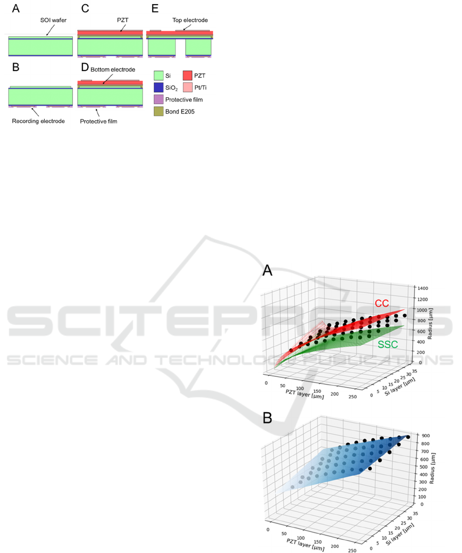
Figure 3: Microfabrication processes used to construct our
PMUT. The different colors represent the different
materials (Si, PZT, SiO
2
, Pt/Ti, protective film, and epoxy
resin E205). The thickness of each material in the figure
does not reflect its actual size.
(5) The top electrodes of the PZT and their wires
to drive the diaphragms were patterned and
formed using the ICP-RIE system (Fig. 3D).
(6) As the final step to create the diaphragm shape,
the Si handle layer was removed from the back
side using a Deep-RIE instrument (MUC-21
ASE-SRE, SPP Technologies Co., Japan). The
last remaining surface-resist layer was
removed using acetone and isopropyl alcohol
(Fig. 3E).
2.3 Measurement of PMUT Properties
To characterize the properties of the fabricated
PMUTs, we measured the resonant frequencies of the
diaphragms. In the present study, four PMUT devices
were used in the measurement. Initially, a cylindrical
acrylic chamber with an internal diameter of 30 mm
was attached to the substrate on a custom-made
printed circuit board (Fig. 2, left). Subsequently,
individual diaphragms in the PMUT were driven by a
sinusoidal signal with a voltage amplitude of 10 V,
which was generated by a multifunction generator
(WF1947, NF Electronic Instruments, Japan) through
a high-speed bipolar amplifier (HSA4014, NF
Electronic Instruments) with a 10-times voltage gain.
The frequencies ranged from 250 to 800 kHz. In the
measurement, the chamber, including the PMUT, was
filled with water. The generated acoustic pressure just
above the diaphragm in the chamber was measured
with a calibrated needle hydrophone (HY05N, Toray
Engineering Co., Japan); the distance between the
diaphragm and the hydrophone was approximately 1
mm. The data obtained from the hydrophone was
recorded by an oscilloscope (DSOX1102G, Keysight
Technologies, USA) with a digital data-acquisition
system. In the measurement, the measured resonant
frequency was obtained as the frequency at which the
maximum peak response was in the frequency range
(i.e., 250–800 Hz) of the applied voltage signals. The
error rate (%) was calculated as 100 × |fr − 500 | / 500
(fr in kHz). In addition, as an index of ultrasound
intensity, we used the time-integral intensity (spatial
peak pulse average, I
sppa
) (Fomenko et al., 2018),
which is defined as the time-averaged power of
acoustic pressure, normalized by the density of the
fluid medium (i.e., water) and the velocity inside the
medium, during a certain period.
3 RESULTS
3.1 Expression of the Three
Parameters
Figure 4 shows the relationships among the size
parameters (r
0
, 𝑑
, and 𝑑
) of the diaphragm under
a resonant frequency of 500 kHz. In both plots, the
Figure 4: Relationships among the three size parameters (r
0
,
d
PZT
, d
Si
). In both plots, the black dots represent the data
points from the FEM simulations of the five-layered
physical model. (A) The red and green curves represent the
relationships obtained Eq. (10) under the CC and SSC,
respectively. (B) The blue curve represents the relationship
described by Eq. (11).
BIODEVICES 2022 - 15th International Conference on Biomedical Electronics and Devices
200
data points indicated by dots were obtained from the
FEM simulation of the five-layered plate model; these
data points are identical in the two plots. The
simulation result indicates that r
0
monotonically
increases as the thickness of the PZT layer or the Si
layer increases. Moreover, Eq. (11) was determined
by applying the least-squares method to the FEM data
(Fig. 4B):
𝑟
(
𝑑
,𝑑
)
=315+ 5.72𝑑
+ 1.98𝑑
−11.9 10
𝑑
𝑑
(11)
The relationship for the five-layered plate was
approximately described as four terms, including a
second-order polynomial of 𝑑
𝑑
( 𝑅
=
0.975). The result (Fig. 4A) shows that the red curve
of the three size parameters for the model under the
CC overestimates the plate radius compared with the
FEM simulation (black dots). By contrast, the green
curve for the five-layered model under the SSC
underestimates the plate radius. These numerical
results suggest that the actual vibration of such plates
corresponds to a boundary condition between the CC
and SSC. In addition, we determined 𝑑
and 𝑑
to
be 100 and 10 μm, respectively, and r
0
to be 580 μm
based on the numerical calculations (Fig. 2).
3.2 Microfabrication of the Diaphragm
We successfully microfabricated the PMUT device
with four diaphragms and eight microelectrodes (Fig.
5). The packaged and enlarged PMUTs are illustrated
in Fig. 5A and 5B, respectively.
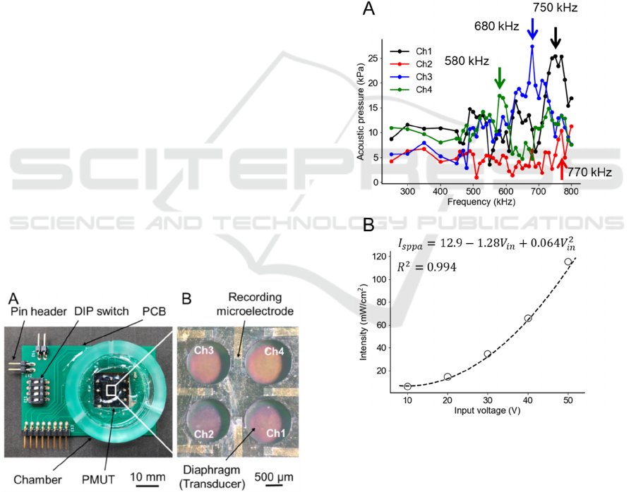
Figure 5: Images of the microfabricated PMUT. (A) The
packaged substrate with the PMUT device. (B) Front side
of the PMUT with four diaphragms (channels, Chs) and
eight electrodes (corresponding to the bottom side of the
schematic illustration in Fig. 3E).
3.3 Response Characteristics of the
Fabricated PMUT
To characterize the response of the fabricated PMUT,
we measured the acoustic pressure of individual
diaphragms when the PMUT was driven by
sinusoidal voltage signals (AC amplitude, 10–50 V).
A typical example of the frequency response for four
diaphragms (channels 1 to 4) is illustrated in Fig. 6A
for an AC amplitude of 10 V. In the pressure
measurement, the maximum of acoustic pressure was
27.4 kPa in channel 3 at 680 kHz. In channels 1, 3,
and 4, resonance phenomena were seen at specific
frequencies, while the resonant acoustic pressure was
smaller in channel 2 (10.4 kPa) than ones in other
channels. In addition, although each of the resonant
Figure 6: Measured acoustic characteristics of the
fabricated PMUT and an intnsity estimation from the data
points. (A) Measured acoustic pressure as a function of
frequency for a sinusoidal voltage input. These frequency
response characteristics were obtained by applying a 10-V
signal at different frequencies. The channel numbers
correspond to those shown in Fig. 5B. The resonant
frequencies are indicated by the arrows in each channles.
(B) Resonant acoustic intensities for different input
voltages. The dashed line represents the relationship
between input voltages and resultant intensities as a
quadratic function described by Eq. (12).
Development of a Piezoelectric Micromachined Ultrasound Transducer using Microfabrication Technology for in Vitro Neuromodulation
201

frequencies was different from the targeted frequency
(i.e., 500 kHz), the error rate of the four diaphragms
was 39 ± 15% for the PMUT device (Fig. 6A).
Overall, the error rate of the seven diaphragms out of
three examined PMUT devices was 42±12%.
Moreover, when the input voltage amplitude was
increased, the response intensity at the resonant
frequency monotonically was increased (Fig. 6B).
The relationship between the response intensity, 𝐼
(in mW/cm
2
), and input voltage amplitude, V
in
(in V),
was approximated by the following quadratic
function (𝑅
=0.994):
𝐼
(
𝑉
)
=12.9 − 1.28𝑉
+ 0.064𝑉
.
(12)
Here, a standard linear regression method was used to
minimize the mean square error between the data
points and the quadratic function of V
in
with three
parameters. From Eq. (12), we can estimate that
individual diaphragms of the PMUT could
approximately generate 0.5 W/cm
2
integral intensity
when a sinusoidal voltage signal of 100 V is applied,
which satisfies our initial target intensity in this study.
4 DISCUSSION
In this study, we developed a MEMS-based PMUT to
locally stimulate brain slices in vitro. We performed
numerical simulations to examine the relationships
between the diaphragm size and the resonant
frequency of the voltage-driven oscillations.
Modeling the multi-layered structure of the PMUT
diaphragms and FEM simulations provided a simple
mathematical expression to estimate the PMUT size.
For the five-layered diaphragm, the curve describing
the relationship among the three size parameters was
positioned between those based on the analytical
results (Eq. (12)) under the CC and SSC. Therefore,
the analytical expression of Eq. (12) gives a rough
estimate of the three size parameters and would be
useful for selecting the size parameters in preliminary
study stages. In addition, the data points obtained
from the FEM simulation were approximated as a
function of the low-order polynomials. The
expression of the low-order polynomials provides a
direct quantitative formula for a specific structural
condition under the resonant frequency of 500 kHz.
Thus, the result of the simple expression may be also
useful for the design of PMUT devices because a
frequency of 500 kHz is often selected for ultrasound
brain stimulation.
On the basis of the numerical results, we designed
and microfabricated a PMUT with four identical
circular diaphragms with 580-μm radius and eight
recording electrodes. To the best of our knowledge,
this is the first time that recording electrodes have
been fabricated in a PMUT, although we did not
evaluate their electrical properties. Furthermore, to
characterize the PMUT properties, including the
intensity and resonant frequency, we measured the
response of the transducer driven by a sinusoidal
voltage input. Some diaphragms (e.g., channel 4) had
a measured value (f
r
= 580 kHz)) close to the target
resonant frequency. We compared the difference
between numerically predicted and measured
resonant frequency with some previous reports. Then,
our mean error rate 39% was relatively large
compared with the previous studies (10-30%) (Cheng
et al., 2019; Dangi et al., 2020; Lee et al., 2019; Lucia
MS, 2017). In addition, among the four diaphragms,
the variance of the resonance frequency was large
(standard deviation = 74 kHz), and frequency-
response characteristics were not identical. Although
the reasons for the differences between the
numerically predicted and measured values are not
clear, we speculate that there was discrepancy
between the fabricated and designed layer thicknesses
of the diaphragms. To confirm this speculation in
future work, we will take scanning electron
microscope images of the PMUT cross-section to
measure the layer thicknesses.
In addition, the input–output characteristic
properties of the diaphragms imply that the intensities
generated by the fabricated PMUT were similar to
those predicted (> 0.5 W/cm
2
), which is sufficient for
the stimulation of brain slices in vitro. Our estimation
requires feeding more than 100-V input into the
device, how the electric artifacts affect the activity of
neural tissue will be one of our future challenges.
Several recent review papers (Cardenas-rojas et
al., 2021; Pasquinelli et al., 2019) summarized four
potential mechanisms by which ultrasound signals
could trigger action potentials: (i) the generation of
capacitive currents as a result of membrane
displacements, (ii) the activation of mechanosensitive
channels, (iii) sonoporation in the lipid bilayer, and
(iv) coupling with membrane waves along the axon.
Effective ultrasonic neurostimulation may be
possible by combining these mechanisms. Examining
the mechanisms will be included in our future work.
ACKNOWLEDGEMENTS
All authors appreciate Dr. Shuichi Murakami and Dr.
Kazuo Satoh (Osaka Research Institute of Industrial
Science and Technology) for their cooperation on
BIODEVICES 2022 - 15th International Conference on Biomedical Electronics and Devices
202

MEMS processes. This work was supported by a
Grant-in-Aid for Exploratory Research [grant number
18K19794] and a Grant-in-Aid for Scientific
Research (B) [grant number 19H04178] (Japan).
REFERENCES
Bewernick, B. H., Hurlemann, R., Matusch, A., Kayser, S.,
Grubert, C., Hadrysiewicz, B., Axmacher, N., Lemke,
M., Cooper-Mahkorn, D., Cohen, M. X., Brockmann,
H., Lenartz, D., Sturm, V., & Schlaepfer, T. E. (2010).
Nucleus Accumbens Deep Brain Stimulation Decreases
Ratings of Depression and Anxiety in Treatment-
Resistant Depression. Biological Psychiatry, 67(2),
110–116. https://doi.org/10.1016/j.biopsych.2009.09.0
13
Cardenas-rojas, A., Pacheco-barrios, K., Giannoni-luza, S.,
Fregni, F., Rehabilitation, S., Hospital, M. G., Loyola,
S. I. De, & Health, M. (2021). HHS Public Access.
20(4), 401–412. https://doi.org/10.1080/147371
75.2020.1738927.Non-invasive
Cheng, C. Y., Dangi, A., Ren, L., Tiwari, S., Benoit, R. R.,
Qiu, Y., Lay, H. S., Agrawal, S., Pratap, R., Kothapalli,
S. R., Mallouk, T. E., Cochran, S., & Trolier-Mckinstry,
S. (2019). Thin Film PZT-Based PMUT Arrays for
Deterministic Particle Manipulation. IEEE
Transactions on Ultrasonics, Ferroelectrics, and
Frequency Control, 66(10), 1605–1615. https://doi.org/
10.1109/TUFFC.2019.2926211
Dangi, A., Cheng, C. Y., Agrawal, S., Tiwari, S., Datta, G.
R., Benoit, R. R., Pratap, R., Trolier-Mckinstry, S., &
Kothapalli, S. R. (2020). A Photoacoustic Imaging
Device Using Piezoelectric Micromachined Ultrasound
Transducers (PMUTs). IEEE Transactions on
Ultrasonics, Ferroelectrics, and Frequency Control,
67(4), 801–809. https://doi.org/10.1109/TUFFC.20
19.2956463
Fomenko, A., Neudorfer, C., Dallapiazza, R. F., Kalia, S.
K., & Lozano, A. M. (2018). Low-intensity ultrasound
neuromodulation: An overview of mechanisms and
emerging human applications. Brain Stimulation,
11(6), 1209–1217. https://doi.org/10.1016/j.brs.20
18.08.013
Hong, E., Trolier-McKinstry, S., Smith, R., Krishnaswamy,
S. V., & Freidhoff, C. B. (2006). Vibration of
micromachined circular piezoelectric diaphragms.
IEEE Transactions on Ultrasonics, Ferroelectrics, and
Frequency Control, 53(4), 697–705. https://doi.org/
10.1109/TUFFC.2006.1611029
Kim, H., Kim, S., Sim, N. S., Pasquinelli, C., Thielscher,
A., Lee, J. H., & Lee, H. J. (2019). Miniature ultrasound
ring array transducers for transcranial ultrasound
neuromodulation of freely-moving small animals.
Brain Stimulation, 12(2), 251–255. https://doi.org/
10.1016/j.brs.2018.11.007
Lee, J., Ko, K., Shin, H., Oh, S. J., Lee, C. J., Chou, N.,
Choi, N., Tack Oh, M., Chul Lee, B., Chan Jun, S., &
Cho, I. J. (2019). A MEMS ultrasound stimulation
system for modulation of neural circuits with high
spatial resolution in vitro. Microsystems and
Nanoengineering, 5(1). https://doi.org/10.1038/s413
78-019-0070-5
Lucia MS, H. K. and T. J. D. C. (2017). HHS Public Access.
Physiology & Behavior, 176(10), 139–148.
https://doi.org/10.1109/ICSENS.2018.8589733.Evalua
tion
Manwar, R., Kratkiewicz, K., & Avanaki, K. (2020).
Overview of ultrasound detection technologies for
photoacoustic imaging. Micromachines, 11(7), 1–24.
https://doi.org/10.3390/mi11070692
Muralt, P., Ledermann, N., Paborowski, J., Barzegar, A.,
Gentil, S., Belgacem, B., Petitgrand, S., Bosseboeuf,
A., & Setter, N. (2005). Piezoelectric micromachined
ultrasonic transducers based on PZT thin films. IEEE
Transactions on Ultrasonics, Ferroelectrics, and
Frequency Control, 52(12), 2276–2288. https://doi.org/
10.1109/TUFFC.2005.1563270
Pasquinelli, C., Hanson, L. G., Siebner, H. R., Lee, H. J., &
Thielscher, A. (2019). Safety of transcranial focused
ultrasound stimulation: A systematic review of the state
of knowledge from both human and animal studies.
Brain Stimulation, 12(6), 1367–1380. https://doi.org/
10.1016/j.brs.2019.07.024
Sato, T., Shapiro, M. G., & Tsao, D. Y. (2018). Ultrasonic
Neuromodulation Causes Widespread Cortical
Activation via an Indirect Auditory Mechanism.
Neuron, 98(5), 1031-1041.e5. https://doi.org/10.1016/
j.neuron.2018.05.009
Tufail, Y., Matyushov, A., Baldwin, N., Tauchmann, M. L.,
Georges, J., Yoshihiro, A., Tillery, S. I. H., & Tyler, W.
J. (2010). Transcranial Pulsed Ultrasound Stimulates
Intact Brain Circuits. Neuron, 66(5), 681–694.
https://doi.org/10.1016/j.neuron.2010.05.008
Wagner, T., Valero-Cabre, A., & Pascual-Leone, A. (2007).
Noninvasive human brain stimulation. Annual Review
of Biomedical Engineering, 9, 527–565. https://doi.org/
10.1146/annurev.bioeng.9.061206.133100
Wah, T. (1962). Vibration of Circular Plates. The Journal
of the Acoustical Society of America, 34(3), 275–281.
https://doi.org/10.1121/1.1928110
Development of a Piezoelectric Micromachined Ultrasound Transducer using Microfabrication Technology for in Vitro Neuromodulation
203
