
An Efficient Workflow for Representing Real-world Urban Environments
in Game Engines using Open-source Software and Data
Arash Shahbaz Badr
a
and Raffaele De Amicis
b
School of Electrical Engineering and Computer Science, Oregon State University, SW Park Terrace, Corvallis, OR, U.S.A.
Keywords:
GIS, Virtual Geographic Environments, Smart Cities, Geovisualization, Immersive Environments,
Open-source, Game Engines.
Abstract:
Game engines (GEs) constitute a powerful platform for visualizing real geographies in immersive virtual
space, and in the last two years, remarkable strides have been made by the leading providers of Geographic
Information System (GIS) software and services, including Esri and Cesium, toward integrating their products
in GEs. Notwithstanding the strengths of GEs, they lack support for many common GIS file formats, and there
exist only limited georeferencing possibilities. Visualizing large-scale geolocations involves high authoring
costs, and the shortcomings of GEs further complicate the workflow. In this paper, we present a workflow
and its implementation for creating large immersive virtual environments that accurately represent real-world
urban areas. The benefits of the presented development are threefold. First, it makes the process more efficient
by automating multiple steps and incorporating a large portion of the workflow inside the GE. Second, it
facilitates an interactive framework by allowing the developer to efficiently extend the scene components with
functionalities and interactions. Third, it entirely relies on open-source software and data, making it suitable
for many non-commercial domains. To showcase the effectiveness of the tool, we created a virtual replica of
an actual city consisting of the terrain, the streets, and the buildings.
1 INTRODUCTION
Immersive technologies constitute an excellent
medium for visualizing geospatial data. The conven-
tional 2D means of representing such data may strip
away important spatial information, and at the same
time, increase the cognitive demand from the users by
requiring them to obtain and understand inherently
3D information through 2D representations (L
¨
utjens
et al., 2019). Immersing users in the 3D space allows
them to experience the space in a “close-to-natural
perspective,” resulting in better spatial perception
of the visualized environment (Keil et al., 2021).
Interactivity is another strength of immersive tech-
nologies. Using traditional input systems, such as
mouse and keyboard, for interacting with 3D spatial
data is less intuitive and often requires more involved
user interfaces, making the interaction less efficient
(Kellogg et al., 2008; C¸
¨
oltekin et al., 2016).
In recent years, game engines (GEs), such as
Unity and Unreal Engine, have demonstrated to be
effective tools for a diverse set of domains, including
a
https://orcid.org/0000-0001-7181-6662
b
https://orcid.org/0000-0002-6435-4364
geovisualization (Laksono and Aditya, 2019). GEs
are capable of visualizing high-fidelity representa-
tions of data in the 3D virtual space and improving
the user experience with interaction, such as naviga-
tion, exploration, and manipulation. Most GEs also
facilitate creation of cross-platform applications sup-
ported by many devices, including virtual and aug-
mented reality (VR and AR) headsets. They also
empower the developers with many useful capabili-
ties such as physics simulation, spatial sound, anima-
tion, and artificial intelligence (Petridis et al., 2012).
Lastly, the availability of powerful, free GEs makes
them a cost-effective alternative to many traditional
software used for visualization and simulation, es-
pecially in non-corporate research settings. These
strengths make GEs an attractive alternative to tradi-
tional GIS visualization software (Carbonell-Carrera
et al., 2021). GEs, however, have not been devel-
oped for the purpose of processing geospatial data.
Therefore, they generally have insufficient support
for geospatial data and georeferencing (Laksono and
Aditya, 2019). Additionally, creating large-scale, in-
teractive, true-to-reality virtual urban environments is
a complex and time-consuming task, giving rise to
Shahbaz Badr, A. and De Amicis, R.
An Efficient Workflow for Representing Real-world Urban Environments in Game Engines using Open-source Software and Data.
DOI: 10.5220/0010916900003124
In Proceedings of the 17th International Joint Conference on Computer Vision, Imaging and Computer Graphics Theory and Applications (VISIGRAPP 2022) - Volume 1: GRAPP, pages
103-114
ISBN: 978-989-758-555-5; ISSN: 2184-4321
Copyright
c
2022 by SCITEPRESS – Science and Technology Publications, Lda. All rights reserved
103

high authoring costs. This paper introduces a process,
discusses the methodology applied, and describes the
tools used for representing the real-world in immer-
sive virtual space. The proposed approach allows de-
velopers to efficiently extend the environment with
customized user interactions, and it solely utilizes
open-source software and data, making it functional
for a wide range of domains and use cases.
It is worth emphasizing that the strength of our
contribution is not only facilitating the efficient devel-
opment of large urban virtual environments with open
software and data. Beyond that, it enables the devel-
opers to easily extend the environment with function-
alities and interactions to customize it to their partic-
ular usage scenario. This includes the procedural cre-
ation and enhancement of functional and interactive
elements by benefiting from the metadata and other
sources of semantic information. This capability is
crucial for many use cases that involve reasonably-
large geo-environments, where the manual handling
of such elements is impracticable, if not impossible.
1.1 Problem Statement
The process of replicating a real-world place in a vir-
tual world is a time-consuming process that normally
comprises many steps and involves different software.
For visualizing a realistic terrain, for instance, the de-
veloper will likely use a GIS software and/or web ser-
vice to acquire the elevation data of the desired area,
and subsequently, use an image processing tool to
convert the GIS data to a heightmap image in a for-
mat supported by the GE. When creating the terrain
in the GE, the developer has to calculate the appropri-
ate scaling in the horizontal and vertical directions to
ensure that the visualized terrain has the same dimen-
sions as the real-world location. Once the terrain is
produced, the features on the earth’s surface, such as
soil, sand, and water, have to be visualized on top of
the terrain, for example, based on a satellite image or
land cover map of the area.
Once the terrain is generated, the environment has
to be populated with 3D representations of natural and
man-made entities to increase the realism of the visu-
alization. Based on the given use case, this may in-
clude flora and fauna, water bodies, buildings, streets,
and urban furniture. For this purpose, 3D geome-
tries and textures have to be produced or obtained
that look reasonably similar to the real-world objects
found in the area. These objects have to be then dis-
tributed throughout the scene in a manner that accu-
rately reflects the characteristics of the real environ-
ment. Manual creation and placing of these items is
tedious and would be unfeasible in large-scale natu-
ral or urban spaces. For such use cases, procedural
methods can make the workflow more efficient.
Besides the visual representations, the environ-
ment may need to be enhanced with further capa-
bilities, such as user interactions, simulations, data
visualizations, animations, and sounds. Integration
of user interactions is particularly important for im-
mersive geographical applications. MacEachren et al.
(1999) have recognized interactivity as one of the four
I’s essential for virtual geo-environments. Similarly,
Hruby et al. (2019) defined interaction as one of the
criteria necessary for forming spatial presence in such
environments. Data-driven creation of functional and
interactive scene objects would significantly improve
the workflow and reduce the authoring costs.
Performing the described steps is time consum-
ing and prone to error, which often involves exten-
sive manual work (L
¨
utjens et al., 2019) and is difficult
to automate (Gruen, 2008). Moreover, parts of this
workflow may need to be repeated each time a change
in the environment is necessary, and the process often
requires a trial-and-error approach until satisfactory
results are achieved (Herwig and Paar, 2002), which
further impedes the development. Accordingly, au-
thoring costs remain a restricting factor for integrat-
ing geospatial data in virtual environments (de Amicis
et al., 2020). Therefore, we identify a need for defin-
ing and implementing a cost-effective workflow that
is primarily contained in the game engine to simplify
the creation of interactive urban virtual environments.
In the remainder of this article, first, an overview
of the relevant previous work is provided. In sec-
tion 3, the proposed methodology is described in de-
tail. Section 4 discusses a use case that was developed
to test the workflow. Lastly, the conclusion and out-
look are articulated in section 5.
2 PREVIOUS WORK
The acquisition, management, analysis, and visual-
ization of three-dimensional databases for urban ar-
eas have become a topic of growing interest to the
scientific community (Prandi et al., 2015). The use of
immersive technologies for exploring and analyzing
geospatial data started gaining traction within the ge-
ography and cartography communities as early as the
1990s (Fischer and Openshaw, 1995; Batty, 1997).
Since then, simulations based on 3D visualization of
very large CityGML models have become standard
applications for planning purposes. One example of
such applications is the large-scale assessment and
visualization of the energy performance of building
stocks conducted within the SUNSHINE project to
GRAPP 2022 - 17th International Conference on Computer Graphics Theory and Applications
104

allow citizens, public administrations, and govern-
ment agencies to perform citywide analyses (Giovan-
nini et al., 2014). Comprehensive representations of
the urban environment from the geometrical, seman-
tic, and appearance points of view are essential for
designing innovative interaction paradigms. For in-
stance, Gune et al. (2018) showcased a multimodal
representation of geospatial data through sonifying
semantic data in a virtual urban environment con-
current with the visual experience. There are also
several examples of digital representations of cities
developed for utilizing VR and AR technologies for
the simulation of Smart City applications (Thomp-
son et al., 2006). Nevertheless, urban virtual environ-
ments have proved on various occasions to be quite
problematic. One area of major concern is the capa-
bilities of those environments to entirely describe all
the complex forms of the urban setup and the volumi-
nous data involved (Liu, 2020).
The process used for creating and enhancing dif-
ferent immersive geographical environments has been
outlined by multiple researchers. An interesting
work-flow was developed by Henry (2018), where a
kite was deployed to capture a large number of aerial
images of the site. Using photogrammetry software, a
digital elevation model (DEM) and an orthophoto of
the area were generated. A number of the reviewed
workflows focused on benefiting from open-source
and public GIS data to facilitate the creation and mod-
ification of virtual environments. Keil et al. (2021) de-
scribed a workflow for accessing and processing such
data while distinguishing between data acquired from
official sources such as governmental agencies versus
sources created and maintained by the online commu-
nities such as Open Street Map (OSM). Edler et al.
(2018) also studied the use of OSM data for enhanc-
ing the virtual environment with 3D objects and meta-
data. The use of open data is a cost-effective solution
for creating geo-environments and gives developers
access to a vast amount of geospatial data from var-
ious official and non-official sources. However, this
also heightens challenges associated with combining
data of varying resolutions and different file formats.
Procedural creation of virtual worlds has also been
investigated. Smelik et al. (2014) and Kelly and Mc-
Cabe (2017) provide extensive surveys of such efforts
and identify a set of criteria for these systems such
as: The environment should look realistic and non-
homogeneous; System’s input requirements should be
minimal and intuitive; Developers should be able to
control the geometry generation and edit the outcome;
System should be seamlessly integrated in the devel-
opment workflow. Robles-Ortega et al. (2013) argued
that procedural approaches have not been fully uti-
lized in many domains, since most of them focus on
creating imaginary virtual worlds rather than recre-
ating real locations. They developed a procedural
approach for generating real-world streets based on
cadastral GIS data that ensures the realistic represen-
tation of the shape and slope of streets and their inter-
sections. A further approach for reconstructing real-
world cities is to use artificial intelligence and com-
puter vision techniques to extract urban entities from
airborne laser scans or images. Bulatov et al. (2014),
for instance, utilized this approach to automatically
generate building geometries and used UAV record-
ings to apply realistic textures to the buildings.
Aside from the academic work, utilizing GEs for
geovisualization has also become an active field in
the industry, which is apparent from the big invest-
ments made in the recent years. Two of the ma-
jor suppliers of GIS software and services, Esri and
Cesium, announced the integration of their platforms
with Unity and Unreal Engine in 2020 and 2021. The
integration facilitates the streaming of topography, 3D
geometries, and raster imagery from the web, or in
the case of ArcGIS Maps, alternatively through local
files. This capability allows developers to visualize
virtually any location on earth with minimal effort.
There are, however, drawbacks too. Making changes
to the streamed environment is cumbersome, since
rather than utilizing the GE editor, modifications need
to be done through third party GIS software, and the
data has to be deployed to the web server or exported
to a local file. Additionally, when streaming the data
over the web, the user experience highly depends on
the available bandwidth. Blurry objects and holes in
the terrain are likely to appear as well, before the tiles
are entirely loaded. Such visual flaws can become
highly detrimental to the sense of presence. Another
major drawback is the difficulty of implementing user
interactions with the streamed objects. Lastly, when
utilizing these platforms, the user is likely bound to
using proprietary software and web services.
Esri’s CityEngine is another powerful commercial
tool for creating large-scale virtual urban spaces. The
software can directly load the topographic informa-
tion of the desired area from the web and create a ter-
rain. In the same process, OSM data can also be im-
ported. A versatile geometry generation tool enables
the creation of geometries for the imported buildings
and streets according to a rule package that can be
customized by the developer. The produced 3D envi-
ronment can be exported to many common file for-
mats, including Unreal Engine’s Datasmith format.
On the flip side, the imported 3D models are static and
cannot be edited in the GE editor, making the devel-
opment workflow inflexible and inefficient. Similarly,
An Efficient Workflow for Representing Real-world Urban Environments in Game Engines using Open-source Software and Data
105

making the imported models functional and interac-
tive is tedious, if not impossible. Lastly, access to a
commercial software (currently licensed at $4,000 for
a single user) is not always possible.
Considering the discussed challenges and short-
comings, we have designed a process and imple-
mented the respective tools with the aim to stream-
line the use of geospatial data for creating interactive
virtual environments that mirror real-world cities.
3 METHODOLOGY
In this section, the software components and their
functionalities are discussed. The methodology is im-
plemented for Unreal Engine version 4.26 (UE4), but
similar procedures can be replicated with other ma-
jor GEs. The next subsection provides an overview
of the software architecture and its components be-
fore describing the objectives achieved through these
components in the following subsections.
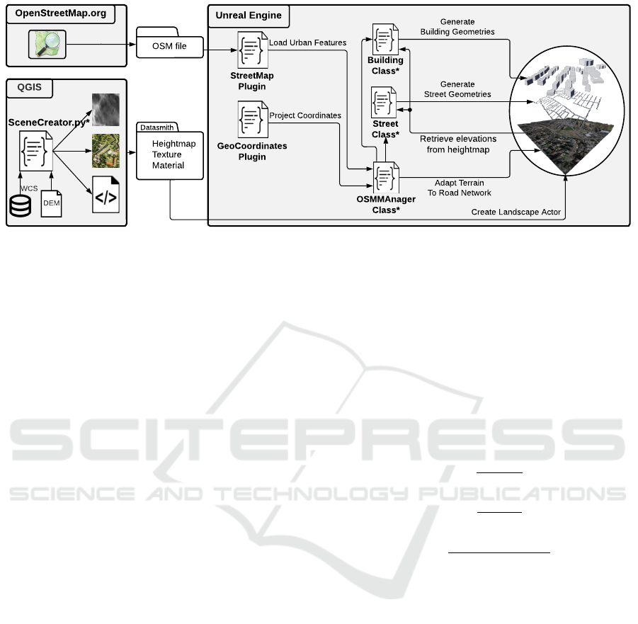
3.1 Software Architecture
Figure 1 shows an overview of our software architec-
ture and the dataflow, where the asterisks indicate the
components developed by the authors. The first com-
ponent is a Python script, called SceneCreator, de-
veloped by us to automate the processing of the geo-
graphical data used for generating a true-to-reality ter-
rain in the 3D space. SceneCreator utilizes the Python
API of the GIS software QGIS, also referred to as
PyQGIS. The script expects a DEM as input, contain-
ing the elevation of earth’s surface within the area of
interest in raster format. The raster is converted to a
heightmap image, where each pixel stores the respec-
tive elevation as a grayscale value. Additionally, an
aerial image is produced to visualize the features of
the environment on terrain’s surface. SceneCreator
outputs the two images along with a Datasmith file,
which can be conveniently imported into UE4 to cre-
ate the landscape and the respective texture material.
The remainder of the workflow is completed in-
side the UE4 editor, which includes loading data,
projecting geolocations to UE4’s coordinate system,
adapting the terrain to the road network, and creat-
ing 3D geometries for streets and buildings. At the
core of this process is a C++ UE4 actor, dubbed OS-
MManager, that has been implemented to coordinate
between various plugins and actors. First, the de-
sired information is read from an OSM file, where the
streets and buildings are stored as sequences of geolo-
cations, expressed in latitudes and longitudes. In the
case of streets, these locations specify the start- and
endpoints of the street segments. In the case of build-
ings, the locations characterize the footprint of the
building. These locations are projected to the scene
space and are used to procedurally construct and dis-
tribute instances of classes that represent the buildings
and streets. The classes have been implemented with
UE4’s Blueprint visual scripting system, and contain
besides the spatial information also the relevant meta-
data and user-defined parameters.
While importing the streets, the developer has the
option to adapt the terrain to the road network in order
to ensure that the sections under the streets are even.
For this purpose, the relevant vertices of the landscape
actor are modified. UE4 creates the landscape actor
based on a heightmap image, where the pixels corre-
spond to the vertices of the tessellated landscape, and
the pixel content specifies the height of the respec-
tive vertex. In order to manipulate this heightmap,
we need to identify which pixels are covered with the
road network. Therefore, a strategy is defined to map
each pair of street nodes to a set of pixels covered by
the respective street segment. Once the affected pix-
els are identified, their value is modified in a manner
that ensures that the terrain is flat under the streets,
while achieving a smooth transition from the start- to
the endpoint of each street segment.
Lastly, geometries are created to visually repre-
sent the buildings and streets in the 3D space. The
geometry creation is performed in each individual in-
stance spawned in the previous steps. In the case of
streets, each street segment is represented with a rect-
angular shape spanned between the start- and end-
point. In the case of buildings, the footprint is ex-
truded with a predetermined height, visualizing an ab-
stract shape of the building.
3.2 Representing the Terrain
To represent the terrain in UE4, a heightmap image
and a texture image are generated using the open-
source software QGIS version 3.20.3. This step as-
sumes the availability of a DEM for the area of inter-
est. A PyQGIS script, called SceneCreator, has been
developed by the authors to process the DEM and to
create the files needed for reproducing the terrain in
UE4. First, the DEM is transformed to a grayscale
heightmap with unsigned 16-bit values, which is the
format accepted by UE4. In the same step, if needed,
the original raster is clipped to the extent of the area of
interest. The heightmap values are also scaled, so that
the range of elevations existent in the area is mapped
to the whole range of 0 to 65535. This is necessary to
maintain accurate scaling of the terrain in the vertical
direction. It is also worth noting that UE4 has a set of
GRAPP 2022 - 17th International Conference on Computer Graphics Theory and Applications
106
Building
Class*
Generate
Building Geometries
Street
Class*
Generate
Street Geometries
Adapt Terrain
To Road Network
OSMMAnager
Class*
GeoCoordinates
Plugin
StreetMap
Plugin
Load Urban Features
Project Coordinates
Unreal Engine
Retrieve elevations
from heightmap
Datasmith
Heightmap
Texture
Material
SceneCreator.py*
QGIS
DEM
WCS
OSM file
OpenStreetMap.org
Create Landscape Actor
Figure 1: An overview of the developed workflow. The components labeled with an asterisks (*) are developed by the authors.
recommended resolutions for the heightmap import,
such as 505, 2017, 4033, etc., along either axis of the
image. This is due to the fact that UE4 divides the
landscape into smaller sections of fixed size. For the
best results, in terms of accuracy and performance,
the recommendations should be followed when cre-
ating a heightmap image. If the heightmap has to be
scaled to a recommended resolution, a bilinear resam-
pling is applied to reduce the pixelation effect.
Additionally, an aerial image of the area is pro-
duced that serves as the texture applied to the sur-
face of the terrain. A convenient method of acquir-
ing the image is to load it through the Web Coverage
Service (WCS), which is a protocol for sharing raster
data over the web. The map is loaded as a new layer
in QGIS, which is subsequently zoomed to the area
of interest and scaled to the desired resolution, while
maintaining the same aspect ratio as the extent of the
area. The resulting layer is then exported as an image.
In addition to the two PNG images, the SceneCre-
ator script also creates a Datasmith file (with exten-
sion .udatasmith). The markup file facilitates im-
porting large collections of assets into UE4 and plac-
ing them in the scene with the hierarchy and trans-
formations specified in the file. This way, complex
scenes built with 3rd party software can be easily re-
constructed in UE4. Aside from this advantage, we
opt for using Datasmith, rather than direct import, for
the following reason. When importing a heightmap
through the UE4 interface, the scaling in the x and y
direction is forced to be equal, implying that the spa-
tial resolution of the pixels in the heightmap is ex-
pected to be the same in both directions. Together
with the limitation of recommended resolutions, this
restriction further curtails developer’s flexibility in
choosing the extent of the desired area. This rule is
not enforced when importing the heightmap through
Datasmith, which makes it a valuable alternative.
A documentation of the Datasmith API was not
available to us, however, we were able to reproduce a
simple file by following the patterns of existing Data-
smith files. This file incorporates a landscape actor
(referencing the heightmap image), a texture (refer-
encing the aerial image), and a material (referencing
the texture). The landscape’s transformation is also
specified in the file. The translation is set to place the
pivot point of the actor (located at the top-left corner
of the terrain) at the origin of the scene. The scaling
is applied according to the following equations:
s
x
=
w
m
· 100
w
p
(1)
s
y
=
h
m
· 100
h
p
(2)
s
z
=
(e
max
− e
min
) · 100
512
(3)
Where s
x
, s
y
, and s
z
are the scales applied to the re-
spective axes. w
m
and h
m
are the width and height
of the visualized area in meters, and w
p
and h
p
are
the width and height of the heightmap image in pix-
els. e
max
and e
min
are the maximum and minimum
elevation present in the DEM. To explain the vertical
scale, the following background is required. By de-
fault, the landscape actor covers a height range from
256 m below the actor’s pivot point to 256 m above it
(the actual maximum is 255.992 m, but the 8 millime-
ters are neglected for the sake of simplicity). Since
the heightmap is expected to be stretched to the full
range of unsigned 16 bits, at the default scale, the dis-
tance between the two extrema spans 512 meters, giv-
ing rise to equation 3. Note that when a landscape is
imported, the default scale value of the actor along all
three axes is 100 rather than 1.
Once the script has completed processing, it pro-
duces an additional text file providing information on
An Efficient Workflow for Representing Real-world Urban Environments in Game Engines using Open-source Software and Data
107

how to set up the georeferencing actor in UE4. Since
the top-left corner of the terrain is placed at scene’s
origin, the georeference of the origin should be set to
the projected coordinates of the northwest point of the
corresponding area. The projected point as well as the
projection method are included in the text file.
3.3 Importing OSM Data
Open Street Map is used to obtain information about
the buildings and streets within the area of interest.
The OSM file, which is in XML format, comprises
elements called nodes, ways, and relations. Nodes
correspond to locations on the earth’s surface and
are specified with their latitude and longitude values.
Ways are an ordered list of nodes used to represent
features such as streets, rivers, coast lines, buildings,
and districts. Relations define a relationship between
a set of nodes, ways, or a combination of both. These
elements can be used, for example, to define a route,
composed of multiple streets, or a building whose
footprint has a hole. Nodes, ways, and relations may
also be associated with a number of tags that represent
the metadata of that entity. Examples of such meta-
data are the name of a street or the number of stories
of a building. Since these tags are optional, one can-
not rely on their availability across all features.
Streets are defined by a set of nodes, referenced
by their IDs. The nodes represent the endpoints of the
street segments connected by a straight line. The seg-
ments correspond to the part of the street between two
intersections. Additionally, new segments are intro-
duced whenever the street deviates from a linear tra-
jectory. Buildings are defined as a sequence of nodes
corresponding to the vertices of a polygon that repre-
sents the footprint of the building. These nodes ap-
pear in the order in which they are connected to each
other, and the first and last nodes are identical to en-
sure a closed polygon.
One simple method of acquiring OSM data is to
download it from online resources. For example, on
the OpenStreetMap website
1
, one needs to only en-
ter the latitudes and longitudes of the corners of the
desired area before downloading the respective OSM
file. To import the downloaded OSM file in UE4, a
customized version of the StreetMap plugin
2
is uti-
lized, which is a C++ plugin originally created for
the engine version 4.19 and has been updated by the
community
3
to make it compatible with newer engine
versions. The tool is capable of importing an OSM
file and storing the information about buildings and
1
openstreetmap.org/export
2
https://github.com/ue4plugins/StreetMap
3
E.g., https://github.com/GameInstitute/StreetMap
streets in respective classes. When importing an OSM
file, the plugin converts the latitudes and longitudes to
UE4 locations. However, it is not possible to choose
the method used for projecting the coordinates, and
it is not possible to associate the origin of the UE4
coordinate system with a specific geolocation. When
an environment has to be formed by various geospa-
tial data (e.g, terrain DEM, aerial image, buildings
and streets locations, and other data-driven features),
it is necessary to be able to associate these elements
with their real-world locations regardless of the co-
ordinate system and spatial projection method used
in the data source. Hence, the aforementioned lim-
itations of the plugin make it difficult to assemble a
geographically accurate scene from different geospa-
tial sources. To make the workflow more flexible and
to allow for a persistent reference point in the scene,
the plugin source code has been modified by us to al-
low access to the latitude and longitude values of the
OSM elements instead of their projected locations.
3.4 Georeferencing
The UE4 editor structures the scene in its own coordi-
nate system, where each unit corresponds to one cm.
In order to be able to represent data-driven entities in
their accurate locations in the scene, a projected coor-
dinate reference system (CRS) is needed to map the
geolocations to the UE4 coordinate system. For this
purpose, the UEGeoCoordinates plugin
4
has been uti-
lized. This plugin, under the name Georeferencing, is
now integrated in the latest version of the engine, ver-
sion 4.27, which was released August 2021. However,
since this project was already set up and functional
with engine version 4.26, we continued working with
the C++ source code of the plugin.
The Georeferencing tool allows the developer to
associate the origin of the UE4 coordinate system
with any particular geographical point. Additionally,
the desired projected CRS can be selected from a wide
range of supported coordinate systems. Once this ref-
erence is set up, any geographical location can be as-
sociated with a location in the UE4 coordinate system,
and vice versa. This allows the developer to easily
place geographical entities in the scene at their accu-
rate location.
3.5 Representing the Buildings
The information about the buildings that are located in
the area of interest can be retrieved for the OSM file.
For each building, the nodes that form its footprint are
transformed to the UE4 coordinate system using the
4
https://github.com/ue4plugins/UEGeoCoordinates
GRAPP 2022 - 17th International Conference on Computer Graphics Theory and Applications
108
georeferencing approach described previously. OSM
nodes generally don’t contain information about their
elevation. Hence, this information has to be obtained
differently. Since the landscape actor is created based
on the heightmap of the area, it is reasonable to ac-
quire the elevation of the terrain at the points corre-
sponding to the nodes and use these values as their
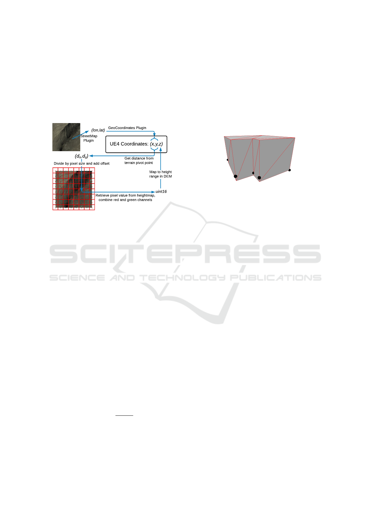
elevation. This process is visualized in figure 2.
(lon,lat)
Get distance from
terrain pivot point
GeoCoordinates Plugin
(d
x
,d
y
)
Divide by pixel size and add offset
UE4 Coordinates: (x,y,z)
StreetMap
Plugin
Retrieve pixel value from heightmap,
combine red and green channels
uint16
Map to height
range in DEM
Figure 2: Calculating the UE4 coordinates of a real-world
point and retrieving the elevation from heightmap. The red
grid illustrates the pixel grid of the heightmap and the re-
spective pixel centers.
To provide some background, a heightmap is im-
ported into UE4 as a 16-bit grayscale image, where
the pixel values represent the height of the landscape
at the corresponding locations. Internally, this infor-
mation is stored in a collection of RGBA textures,
where every channel occupies 8 bits. The most sig-
nificant byte of the 16-bit height value is stored in the
red channel and the least significant byte is stored in
the green channels. When computing the height cor-
responding to a pixel in the heightmap texture, first
the binary representations of the red and green val-
ues are concatenated to a 16-bit unsigned int number.
Given the previous discussion on the vertical scaling
of the terrain, at the default scale, 0 represents a height
of -256 m, whereas 2
16
−1 represents +256 m with re-
spect to the landscape’s pivot point. The pivot point is
located at the top-left corner of the landscape, halfway
between the lowest and highest elevations. Given the
actor’s location and scale along the vertical axis, de-
noted by t
z
and s
z
, the height in the UE4 space, h, can
be computed according to the formula in equation 4,
where p represents the 16-bit pixel value.
h = t
z
+ s
z
(512 ·
p
2
16
− 1
− 256) (4)
To calculate the elevation of a node, first, the pixel
in the heightmap is identified that corresponds to this
point, and the respective pixel content is converted
to a height value using the above approach. For
each building, the elevation of all respective nodes are
computed first. Subsequently, the minimum of these
values is used as the height of the building’s base.
This ensures that the floor (and implicitly the roof)
are aligned horizontally, which achieves the best vi-
sual results, even though it may cause portions of the
building to be hidden below the landscape. Figure 3
depicts an example of a building geometry and the re-
spective footprint nodes.
Figure 3: Extruding the building geometry from footprint
nodes. The building’s base is at height equal to the elevation
of the lowest node (node at the bottom-right corner). Red
edges visualize the triangulation of the geometry.
A UE4-Blueprint class is implemented for repre-
senting the buildings in the UE4 scene. This class
contains the UE4 locations of the vertices of the build-
ing footprint, some parameters for geometry creation
(e.g., height and texture material), as well as some
metadata. When the OSM data is processed, an in-
stance of the building class is spawned for each build-
ing available in the OSM file. Each instance is pop-
ulated with the respective projected locations and the
desired metadata, if available.
The Blueprint class also generates an abstract 3D
representation of the building. For this purpose, a
CustomMesh component is created that is filled with
the triangulation of the building’s geometry. Given
the ordered list of vertices of the footprint, for each
consecutive pair of vertices, two new vertices are
added above the given pair, representing the respec-
tive roof corners. These four vertices form a rectan-
gular wall of the building that can be represented with
two triangles. To create the roof (and possibly the
floor), the Ear Clipping algorithm is implemented in
the Blueprint class based on the version outlined in
(Mei et al., 2013). Since OSM data is not always op-
timized, the algorithm is further extended to be able
to handle edge cases such as degenerate triangles and
identical consecutive nodes.
Even though the Ear Clipping algorithm has O(n
2
)
complexity, it was deemed as feasible for our use case
as the number of the vertices of a building footprint is
expected to be small. Moreover, this number is ex-
pected to be significantly smaller than the number of
the buildings, which makes the overall computation
An Efficient Workflow for Representing Real-world Urban Environments in Game Engines using Open-source Software and Data
109
time of the procedure less dependent on the complex-
ity of individual triangulations. A further limitation
of the Ear Clipping algorithm (and many other algo-
rithms) is that polygons with holes are not supported.
Since the StreetMap plugin does not handle such en-
tities, this drawback of the triangulation algorithm is
not the limiting factor of our specific implementation.
Since UE4 by default treats triangles as one-sided
faces, they need to be added in counterclockwise
(CCW) order to ensure that the rendered face is visi-
ble from outside of the building. To specify the order,
we first determine for each footprint, whether the ver-
tices are labeled in clockwise or CCW order. This can
be judged using the signed version of the Shoelace
formula for computing the area of a planar polygon:
1
2
n
∑
i=1
det
x
i
x
i+1
y
i
y
i+1
(5)
Where x
i
and y
i
are the Cartesian coordinates of the
i−th vertex. If the above sum is positive, the foot-
print is winding CCW and vice versa. Based on this
winding, the triangles are added to the CustomMesh
component in CCW order.
3.6 Representing the Street Network
The street data, extracted from an OSM file, serve two
purposes: (1) The landscape can be modified to en-
sure that it is aligned with the road network. (2) 3D
representations of the streets are created and placed in
the scene. A description of these procedures follows.
3.6.1 Adapting the Terrain
Most publicly available DEMs do not have a spa-
tial resolution high enough to ensure that the sur-
face of the roads are captured accurately. Even if
the DEM provides the required resolution and pre-
cision, it is likely that the 3D software used for vi-
sualizing the terrain will require the resolution to be
scaled down to avoid performance bottlenecks when
visualizing large areas, such as entire cities. Unreal
Engine, for instance, accepts a heightmap image of up
to 8160x8160 pixels for a landscape. If a spatial res-
olution of 1 meter per pixel is desired, this heightmap
covers an area of roughly 67 km
2
. A landscape of this
size, however, is tessellated with over 133 million tri-
angles, which is not feasible for many platforms.
On the other hand, low spatial resolution in the
DEM may result in an uneven terrain along the width
and length of a road. If the streets are represented
with 3D geometries, visual errors will occur when the
street geometries intersect with the terrain surface or
are not correctly aligned on it. Figure 4 demonstrates
some of these issues in an environment created us-
ing CityEngine 2019 and imported into UE4 through
the Datasmith protocol. CityEngine has a feature for
aligning the terrain to shapes, which was utilized.
Nevertheless, the alignment is not maintained after
import since CityEngine and UE4 process and vi-
sualize the heightmap image differently. Our work-
flow modifies the landscape actor in UE4 to minimize
these visual errors. We tested different methods for
modifying the landscape procedurally, such as defin-
ing landscape splines, creating landmass brushes, and
directly modifying the heightmap of the landscape.
We chose the last approach, as it produced the best
visual results, while requiring no action from the de-
veloper aside from setting a few parameters.
Figure 4: Visual errors are possible when the terrain and the
scene elements are not well-aligned.
For performance reasons, UE4 splits the land-
scape into components. Each component is of square
shape and may itself contain either a single section or
a 2-by-2 grid of sections. Each section contains a grid
of mxm quads, with m = 2
n
−1 and n ∈ {3, .., 8}. Each
quad is tessellated with 2 triangles. As mentioned ear-
lier, the information from the input heightmap image
is stored in a set of texture instances. These textures
are associated with landscape components rather than
the entire landscape, however, several landscape com-
ponents may share the same heightmap texture.
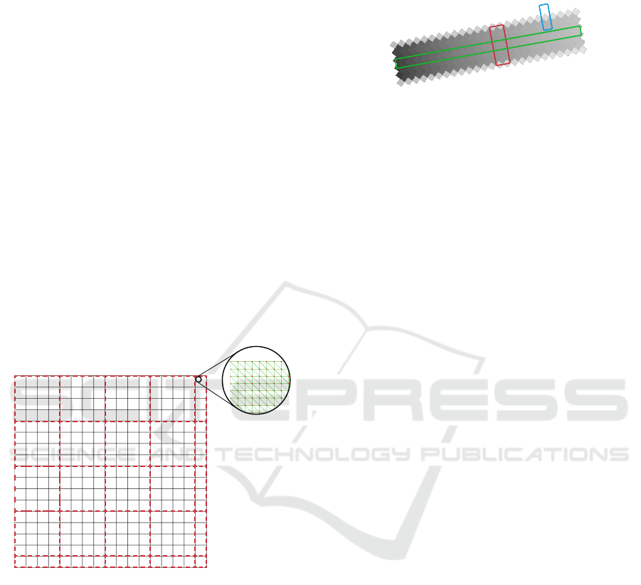
For example, given a 2160x2160 pixel heightmap,
UE4 may create a landscape actor as demonstrated
in figure 5. The landscape is composed of 289 com-
ponents visualized by the black 17-by-17 grid. Each
component has one section with a 127-by-127 grid of
quads, and each quad is tessellated with two triangles.
The green grid depicts the tessellation for a portion
of one of these sections. The imported heightmap is
split into smaller segments and stored as instances of
a texture data structure. The coverage of each texture
is outlined with the red dashed borders. As shown in
GRAPP 2022 - 17th International Conference on Computer Graphics Theory and Applications
110
the figure, every 4-by-4 set of components share a tex-
ture of size 512x512 pixels for storing the respective
height values. The components in the last row and
column of the grid are associated with textures that
are of size 128x512 or 512x128 or 128x128, depend-
ing on their location in the grid. This gives rise to a to-
tal of 25 textures. Note that the total number of pixels
in all textures is 4·512 +128 = 2176 along each axis,
which is larger than the original 2160 pixels. This is
due to the fact that UE4 inserts duplicate pixels at the
intersection of the sections and components. In this
example, pixels at the 127-th row and column corre-
spond to the same locations on the landscape as the
pixels in the 128-th row and column. This pattern is
repeated for every 127-th row and column of textures.
When manipulating the textures programmatically, it
is essential to assign the same value to these overlap-
ping pixels, otherwise, a crack will appear in the land-
scape. Furthermore, when identifying the pixel that
represents a specific location on the terrain, first, the
containing texture needs to be determined, and within
that texture, an offset has to be applied to the index of
the respective pixel to account for the duplicate pixels.
Figure 5: The landscape in UE4 is structured as a set of
components (black grid). Component are formed by a fixed
number of triangles (green). Multiple components can share
the same texture instance for storing the height values (red).
In the proposed method, the pixel values in the
heightmap textures are manipulated to ensure that the
parts of the landscape that are covered by a street are
flat and don’t show abrupt height changes. To achieve
this, the following rules are followed for modifying
the pixel values: (1) Along the length of a street seg-
ment, the pixels are assigned by interpolating between
the heights of the respective endpoints. (2) Along the
width of a street, the pixels are assigned the same
value. (3) Boundary pixels are assigned a value equal
to the mean of the heights of two adjacent pixels along
the line perpendicular to the street (one neighboring
pixel on the street and one outside). Figure 6 illus-
trates how these rules work together.
Figure 6: The heightmap is adapted to the streets. Along
the street, pixels are interpolated between the values of the
endpoints (green). Across the street, pixels have the same
value as the respective center point (red). Boundary pixels
are assigned the average of their neighboring pixels (blue).
As the first step, for each street segment, we iden-
tify the affected heightmap pixels. These pixels form
a rectangle that spans between the start- and endpoint
of the segment and has a width, w, corresponding to
the predetermined width of the road. These pixels are
identified by a modified version of the Bresenham’s
line algorithm (Bresenham, 1965), which takes the
width of the rectangle into account and ensures that
all the pixels in the respective rectangle are captured.
In particular, first, the pixels that represent the line
connecting the start- and endpoint are determined us-
ing the Bresenham’s algorithm. Subsequently, for
each one of these pixels, we specify the perpendic-
ular line segment of length w centered at that pixel
(i.e., the line enclosed by the red box in figure 6). The
endpoints of this line segment represent the boundary
of the rectangle corresponding to the current pixel.
All the pixels that are covered by this perpendicular
line segment will be assigned the same pixel value.
This value is computed by a linear interpolation be-
tween the heights of the endpoints of the street seg-
ment. For this purpose, the real-world elevations at
the location of street segments’ endpoints as well as
points surrounding the street are acquired. These ele-
vations are read from the heightmap textures based on
the same approach used for calculating the elevation
of buildings’ nodes. The acquired height values are
subsequently used to determine the pixel value of the
points affected by the street according to the relation
specified in equation 4.
3.6.2 Creating Street Geometry
Similar to buildings, a UE4 class is developed to
represent the streets in the immersive environment.
When the OSM data is processed, an instance of the
street class is spawned for each street and initialized
with the UE4-locations of the nodes as well as the de-
sired metadata. The locations of the nodes are used to
create and set a spline component along the street.
When generating the 3D geometry, for every con-
An Efficient Workflow for Representing Real-world Urban Environments in Game Engines using Open-source Software and Data
111

secutive pair of spline points, a SplineMesh compo-
nent is added between them. The benefit of using
spline meshes, over simple static meshes, is that with
spline meshes, the engine automatically deforms the
underlying mesh to adapt it to the shape of the spline.
In our case, a simple cube is used as the geometry,
which is stretched along the street segment and scaled
with the predefined street width.
4 TEST SCENARIO
To examine the effectiveness of the developed work-
flow, we created the 3D representation of a real urban
space using UE4. The location chosen for this sce-
nario is the central part of the city of Seaside, along
the Oregon coast in the United States. For visualizing
the terrain, we utilized a DEM representing a larger
area surrounding the desired location. Using the de-
veloped PyQGIS SceneCreator script, the DEM was
clipped to the area of interest by specifying the four
corners of a rectangle identified with the respective
latitudes and longitudes. Further processing is per-
formed as outlined in subsection 3.2. The resulting
image is a grayscale heightmap of size 2160x2160
pixels, covering an area of roughly 1.30x1.36 km.
The accompanying texture image is acquired from
the World Imagery
5
map dataset through WCS. The
Datasmith file produced by the script is imported into
UE4 using the Datasmith Importer, which places a
landscape of accurate proportions in the scene. Sub-
sequently, a georeference actor is placed in the scene
and the projected coordinates of the origin are config-
ured using the information computed by the script.
Additionally, an OSM file is acquired through
the OpenStreetMap website, using the same latitudes
and longitudes used in SceneCreator. Utilizing the
StreetMap plugin, the file is imported into UE4. The
developed OSMManager actor is placed in the scene
and is configured with references to the imported
OSM file as well as the classes representing the build-
ings and streets. A screenshot of the user interface of
the actor is shown in figure 7. Once the actor is set up,
the developer can load the road network by pressing a
button. This process spawns an instance of the street
class for each street represented in OSM and adapts
the landscape to the road network, as described previ-
ously. For the visualized area, 239 street instances are
distributed throughout the scene, with a total length of
over 24.4 km across all streets. Note that a real-world
street may be represented with multiple way elements
in the OSM file, each corresponding to a portion of it.
5
http://server.arcgisonline.com/ArcGIS/rest/services/
World Imagery/MapServer
Subsequently, the developer can select all the street
instances in the scene (or any subset of them) and
press another button to create the corresponding ge-
ometries. Similarly, the building instances are dis-
tributed in the scene with the push of a button and
initialized with the vertices of the footprint. In our
test case, 1206 buildings are generated. Collectively,
the building footprints comprise 6216 nodes, and a
total of 16192 triangles are produced.
Figure 7: Interface of the OSMManager actor.
To measure the time needed for the above com-
putations, we logged the computation time of each
step. The tests are repeated 5 times and the aver-
age value is reported. These experiments were con-
ducted on a Windows workstation with Intel Xeon E5-
2690 2.60GHz CPU, 256 GB of RAM, and NVIDIA
Quadro P6000 graphics card. The procedure for ex-
tracting the street information, populating the scene
with street instances, and adapting the landscape took
on average 3.65 seconds. Extracting the building in-
formation and creating the instances required on av-
erage 1.07 seconds. The average times for generating
the geometries of the streets and buildings were 0.82
and 0.98 seconds respectively. These times are mea-
sured for the processing done by our actors. Addi-
tionally, when large numbers of geometries are added
to the scene, UE4 editor may freeze for a short mo-
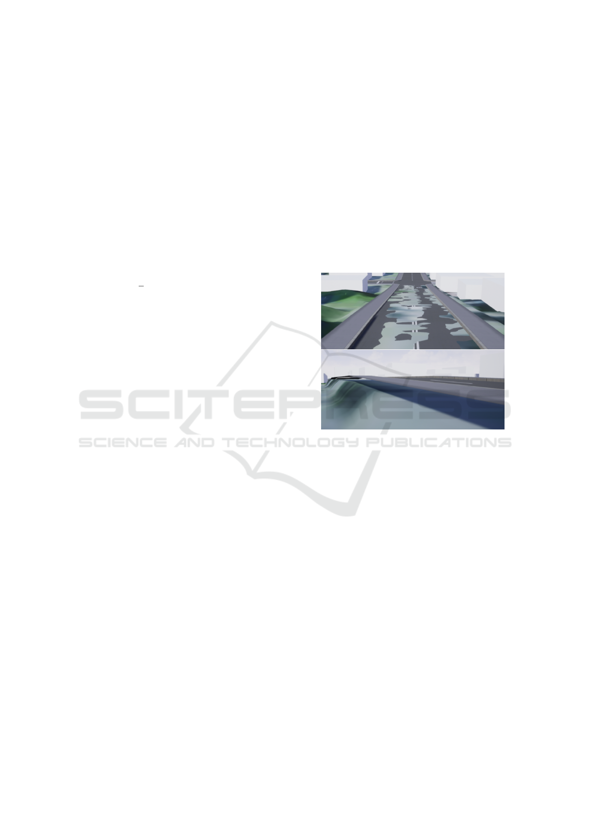
ment to render the scene. Screenshots of the created
environment can be seen in figure 8.
GRAPP 2022 - 17th International Conference on Computer Graphics Theory and Applications
112
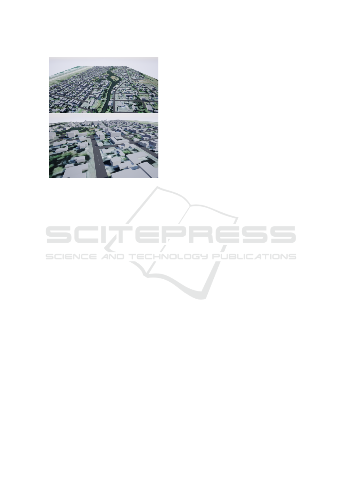
Figure 8: Screenshots of the created environment.
5 CONCLUSION AND OUTLOOK
In this work, we introduced a workflow, discussed the
respective methodology, and described the tools uti-
lized for making it possible to efficiently construct
virtual worlds that replicate large real-world urban
spaces. The process relies entirely on open-source
software and data, which makes it attractive for a
wider audience within the non-commercial research
domain and beyond. The workflow also facilitates
an interactive framework, where the developer is able
to tailor the environment and the interactions to the
use case at hand by extending the classes represent-
ing the scene elements. For instance, consider a sce-
nario where the effects of an earthquake on a city have
to be simulated in the 3D space. With the proposed
approach, individual instances of the building class
can compute the degree of damage suffered, for ex-
ample, based on the building’s age and material type,
as queried from the metadata. Since in our workflow
the geometry creation is procedural, each building is
capable of visualizing its own damage at run time.
With the developed workflow, given a DEM of
the area of interest, within minutes the terrain can be
produced and populated with urban features (streets
and buildings), provided that the developer is well-
familiar with the process and tools. This comes with
the caveat that every location has its own character-
istics and complexities, which will likely require the
developer to try different parameters or make modi-
fications to the process or preprocess the data. This
means that the realistic time of creating a new loca-
tion is expected to be higher. Nevertheless, this work-
flow is significantly more efficient than many existing
approaches, making it a viable option for rapid proto-
typing. This efficiency is brought about by two major
factors. First, the majority of the process is performed
within the GE, making the use of external tools, such
as 3D modelling or image processing software, ob-
solete. Second, the process is largely automated. In
most steps, the developer only needs to set some pa-
rameters and trigger the respective function calls.
Despite the power of the implemented framework,
there is room for improvement in future iterations. We
believe the efficiency can be increased by incorporat-
ing the totality of the workflow inside GE. Currently,
the heightmap image, the aerial image, and the OSM
file need to be produced by external software and im-
ported into UE4. Being able to conduct those tasks
from the GE will speed up the development and im-
prove the developer experience. This can be achieved,
for example, by implementing an interface to open li-
braries, such as GDAL. Another avenue that can be
pursued is to capitalize on the recent developments in
the immersive GIS industry and benefit from the inte-
gration of commercial services, such as Esri and Ce-
sium. These solutions are, however, proprietary and
have further drawbacks as discussed previously.
Enhancing the aesthetics of the environment is an-
other desired objective. Using aerial imagery for vi-
sualizing the terrain surface is a suitable solution for
bird’s-eye view settings, but for first-person experi-
ence, this is less satisfactory. A favorable approach
would be to segment aerial images using artificial in-
telligence and to paint the terrain in accordance with
these segments. Similarly, land cover maps could be
used to automatically populate the scene with natu-
ral features, such as vegetation and water bodies. The
created geometries for the streets and buildings could
also be expanded to more elaborate shapes with pho-
torealistic textures. A further enhancement would be
to deploy intelligent agents in the scene to represent
crowds and traffic. These improvements could boost
the realism of the environment noticeably, and conse-
quently, improve the user experience.
ACKNOWLEDGEMENTS
This research has been partially supported by the Na-
tional Science Foundation (NSF) CIVIC Innovation
Challenge - Resilience to Natural Disasters (Award
number: 2044098).
An Efficient Workflow for Representing Real-world Urban Environments in Game Engines using Open-source Software and Data
113

REFERENCES
Batty, M. (1997). Virtual geography. Futures, 29(4-5):337–
352. Publisher: Elsevier.
Bresenham, J. (1965). Algorithm for computer control of a
digital plotter. IBM Systems Journal, 4(1):25–30.
Bulatov, D., H
¨
aufel, G., Meidow, J., Pohl, M., Solbrig, P.,
and Wernerus, P. (2014). Context-based automatic
reconstruction and texturing of 3d urban terrain for
quick-response tasks. ISPRS Journal of Photogram-
metry and Remote Sensing, 93:157–170.
Carbonell-Carrera, C., Saorin, J., and Meli
´
an D
´
ıaz, D.
(2021). User VR Experience and Motivation Study in
an Immersive 3D Geovisualization Environment Us-
ing a Game Engine for Landscape Design Teaching.
Land, 10(5):492.
de Amicis, R., Bernstein, W. Z., Scholz, J., Radkowski,
R., Sim
˜
oes, B., Lieberman, J., and Prather, E. (2020).
Merging Geospatial Technologies with Cross Reality
in the context of smart manufacturing systems. In
2020 IEEE International Symposium on Mixed and
Augmented Reality Adjunct (ISMAR-Adjunct).
Edler, D., Husar, A., Keil, J., Vetter, M., and Dickmann,
F. (2018). Virtual Reality (VR) and Open Source
Software: A Workflow for Constructing an Interac-
tive Cartographic VR Environment to Explore Urban
Landscapes. KN - Journal of Cartography and Geo-
graphic Information, 68(1):5–13.
Fischer, M. and Openshaw, S. (1995). A Framework for Re-
search on Spatial Analysis Relevant to Geo-Statistical
Informations Systems in Europe.
Giovannini, L., Pezzi, S., di Staso, U., Prandi, F., and
de Amicis, R. (2014). Large-Scale Assessment and
Visualization of the Energy Performance of Buildings
with Ecomaps - Project SUNSHINE: Smart Urban
Services for Higher Energy Efficiency:. In Proceed-
ings of 3rd International Conference on Data Man-
agement Technologies and Applications, pages 170–
177, Vienna, Austria. SCITEPRESS.
Gruen, A. (2008). Reality-based generation of virtual en-
vironments for digital earth. International Journal of
Digital Earth, 1(1):88–106.
Gune, A., De Amicis, R., Sim
˜
oes, B., Sanchez, C., and
Demirel, O. (2018). Graphically Hearing: Enhanc-
ing Understanding of Geospatial Data through an In-
tegrated Auditory and Visual Experience. IEEE Com-
puter Graphics and Applications, 38(4):18–26.
Herwig, A. and Paar, P. (2002). Game Engines: Tools for
Landscape Visualization and Planning? Trends in GIS
Virtualization in Environmental Planning and Design.
Hruby, F., Ressl, R., and de la Borbolla del Valle, G.
(2019). Geovisualization with immersive virtual envi-
ronments in theory and practice. International Journal
of Digital Earth, 12(2):123–136.
Keil, J., Edler, D., Schmitt, T., and Dickmann, F. (2021).
Creating Immersive Virtual Environments Based on
Open Geospatial Data and Game Engines. KN -
Journal of Cartography and Geographic Information,
71(1):53–65.
Kellogg, L., Bawden, G., Bernardin, T., Billen, M.,
Cowgill, E., Hamann, B., Jadamec, M., Kreylos, O.,
Staadt, O., and Sumner, D. (2008). Interactive Visual-
ization to Advance Earthquake Simulation. Pure and
Applied Geophysics, 165(3):621–633.
Kelly, G. and McCabe, H. (2017). A Survey of Procedural
Techniques for City Generation. The ITB Journal.
Laksono, D. and Aditya, T. (2019). Utilizing A Game
Engine for Interactive 3D Topographic Data Visu-
alization. ISPRS International Journal of Geo-
Information, 8(8):361.
Liu, X. (2020). Three-Dimensional Visualized Urban Land-
scape Planning and Design Based on Virtual Reality
Technology. IEEE Access, 8:149510–149521.
C¸
¨
oltekin, A., Hempel, J., Brychtova, A., Giannopoulos, I.,
Stellmach, S., and Dachselt, R. (2016). Gaze and Feet
as Additional Input Modalities for Interacting with
Geospatial Interfaces. In ISPRS Annals of the Pho-
togrammetry, Remote Sensing and Spatial Informa-
tion Sciences, volume III-2. Copernicus GmbH.
L
¨
utjens, M., Kersten, T., Dorschel, B., and Tschirschwitz, F.
(2019). Virtual Reality in Cartography: Immersive 3D
Visualization of the Arctic Clyde Inlet (Canada) Using
Digital Elevation Models and Bathymetric Data. Mul-
timodal Technologies and Interaction, 3(1):9.
MacEachren, A., Edsall, R., Haug, D., Baxter, R., Otto, G.,
Masters, R., Fuhrmann, S., and Qian, L. (1999). Vir-
tual environments for geographic visualization: po-
tential and challenges. In Proceedings of the 1999
workshop on new paradigms in information visualiza-
tion and manipulation, NPIVM ’99, pages 35–40. As-
sociation for Computing Machinery.
Mei, G., Tipper, J., and Xu, N. (2013). Ear-Clipping Based
Algorithms of Generating High-Quality Polygon Tri-
angulation. In Lu, W., Cai, G., Liu, W., and Xing, W.,
editors, Proceedings of the 2012 International Con-
ference on Information Technology and Software En-
gineering, Lecture Notes in Electrical Engineering,
pages 979–988. Springer.
Petridis, P., Dunwell, I., Panzoli, D., Arnab, S., Protopsaltis,
A., Hendrix, M., and de Freitas, S. (2012). Game
Engines Selection Framework for High-Fidelity Seri-
ous Applications. International Journal of Interactive
Worlds, pages 1–19.
Prandi, F., Devigili, F., Soave, M., Di Staso, U., and
De Amicis, R. (2015). 3D web visualization of huge
CityGML models. The International Archives of the
Photogrammetry, Remote Sensing and Spatial Infor-
mation Sciences, XL-3/W3:601–605.
Robles-Ortega, M. D., Ortega, L., Coelho, A., Feito, F., and
de Sousa, A. (2013). Automatic Street Surface Mod-
eling for Web-Based Urban Information Systems. Ur-
ban Planning and Development, 139(1):40–48.
Smelik, R., Tutenel, T., Bidarra, R., and Benes, B. (2014).
A Survey on Procedural Modelling for Virtual Worlds.
Computer Graphics Forum, 33(6):31–50.
Thompson, E. M., Horne, M., and Fleming, D. (2006). Vir-
tual Reality Urban Modelling - An Overview. In Pro-
ceedings of 6th Conference of Construction Applica-
tions of Virtual Reality.
GRAPP 2022 - 17th International Conference on Computer Graphics Theory and Applications
114
