
MUFF: A Low-cost Motorized Positioner Developed by Additive
Manufacturing to Obtain Multi-focus Images
Gustavo Lelis da Silva
1 a
, Jorge Stolfi
1 b
and Helena Cristina da Gama Leit
˜
ao
2 c
1
State University of Campinas (UNICAMP), Campinas, SP, Brazil
2
Federal Fluminense University (UFF) Niteroi, RJ, Brazil
Keywords:
Optical Microscopy, 3D Printing, Multi-focus Stereo, Photometric Stereo, Arduino.
Abstract:
Multifocal microscopy is an established technique to combine several reflected-light microscopy images of an
object, each with a limited depth of focus, into a single image that shows the whole object in focus. Photo-
metric stereo is an independent technique to recover the third dimension of an opaque object, given several
images taken from the same viewpoint with different illumination conditions. We describe a low-cost motor-
ized positioning device for the automatic acquisition of multiple reflected-light low-power microscope images
of an object for combined multifocal and photometric stereo capture of millimeter-scale objects. The device
automatically varies the microscope-to-object distance and the light direction, under control of an Arduino
microcontroller. The device consists of a supporting frame, a microscope holder with motorized vertical dis-
placement, an illumination stage with multiple light sources, and control electronics. The mechanical and
structural parts are largely 3D-printed. The electronics is based on the Arduino microcontroller. The device is
driven through an USB cable by a Python program that runs on a PC.
1 INTRODUCTION
Multi-focus Stereo: An optical microscope usually
can focus only on those points of the target object
that lie in a narrow range of distances from the ob-
jective lens; that is, between two close planes per-
pendicular to the optical axis. The distance ε be-
tween these planes, called depth of field, is inversely
proportional to the magnification and to the effective
aperture of the microscope (Ciciliato and Chiquito,
1995). If the target object cannot fit between these
two planes, it is necessary to acquire several images
J
i
for i = 1,2,..., n, varying the object-lens distance,
so that every visible point of the object is in focus in
at least one of the images. The number n of images
must be at least H/ε, where H is the total extent of
the object in the Z-direction. These images then can
be composited into a single multi-focus image (MFI)
e
J that shows the whole object in focus. See Figure 1
As a by-product, this technique also provides infor-
mation about the three-dimensional shape of the ob-
ject, in the form of a height map — an image
e
Z that,
a
https://orcid.org/0000-0002-3834-412X
b
https://orcid.org/0000-0002-3159-4839
c
https://orcid.org/0000-0002-4722-4963
for each pixel of the combined image, specifies the
approximate Z coordinate of the point on the object’s
surface that is visible at that pixel. This method to re-
cover the 3D shape of the object is known as shape
from focus (Nayar, 1989; Fernandes and Torre
˜
ao,
2010), depth from focus (Grossmann, 1987) or multi-
focus stereo (MFS).
The principles of multi-focus stereo were de-
scribed in 1987 by Grossmann (Grossmann, 1987)
and in 1989 by Nayar (Nayar, 1989). A brief sur-
vey of the field was provided in 2012 by Thiery and
Green (Thiery and Green, 2012), and also in 2003 by
Zamofing et al. (Zamofing and Hugli, 2004). Applica-
tions of MFI and MFS include the imaging of miner-
als (Thiery and Green, 2012), manufacturing (Zamof-
ing and Hugli, 2004), paleontology (Bercovici et al.,
2009), and archaeology (Plisson and Zotkina, 2015).
Photometric Stereo: Another technique for captur-
ing the three-dimensional shape of an object uses
several images J
(k)
for k = 1,2, ... ,m, taken from
the same viewpoint but under different illumina-
tions (Woodham, 1980; Coleman and Jain, 1982).
Analysis of these images yields surface normal map
b
N and an intrinsic color map
b
A, that specify the incli-
144
Lelis da Silva, G., Stolfi, J. and Leitão, H.
MUFF: A Low-cost Motorized Positioner Developed by Additive Manufacturing to Obtain Multi-focus Images.
DOI: 10.5220/0010913500003121
In Proceedings of the 10th International Conference on Photonics, Optics and Laser Technology (PHOTOPTICS 2022), pages 144-151
ISBN: 978-989-758-554-8; ISSN: 2184-4364
Copyright
c
2022 by SCITEPRESS – Science and Technology Publications, Lda. All rights reserved
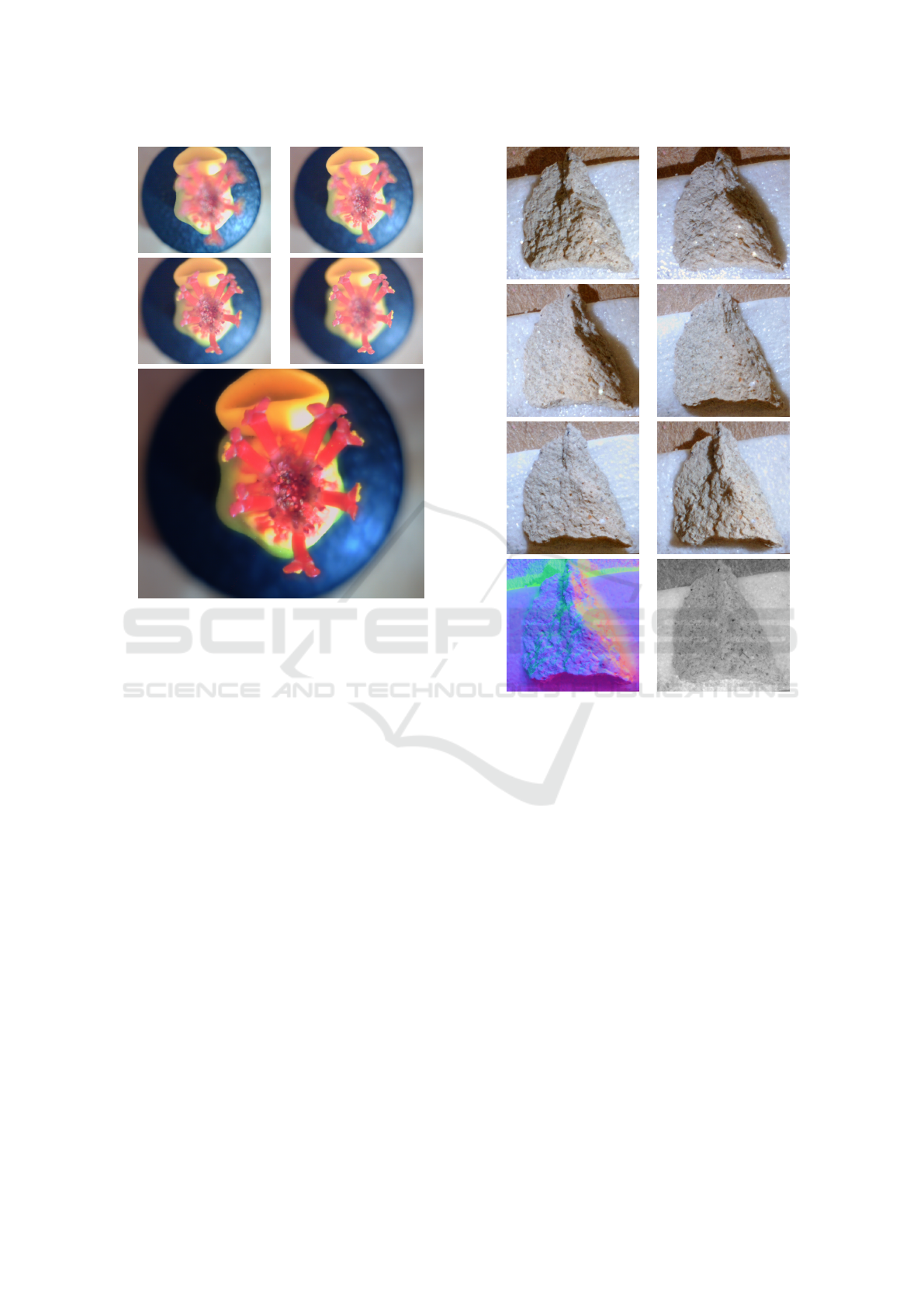
Figure 1: Illustration of the multi-focus imaging technique.
The four images at top are frames J
1
, J
9
, J
17
, and J
25
of
a 25-frame stack.The larger image at bottom is the sharp
composite image
e
J.
nation and per-channel albedo of the visible surface,
respecively, at each pixel. The slope information then
can be integrated to obtain a height map
b
Z (Sarac-
chini et al., 2012). The number m of images must be
at least 6 to provide sufficient data for this computa-
tion (Leit
˜
ao et al., 2008), but several more are needed
if there are complicating factors like projected shad-
ows, glossy highlights, significant self-lighting, etc.
See figure 2. This technique is called Photometric
stereo (PMS).
The physical principles of photometric stereo have
been known since the development of photometry in
1760 by Lambert (Lambert, 1760), and their use by
astronomers in the early 20th century (Rindfleisch,
1966). The first mathematically sound formulation
was given by Woodham in 1980 (Woodham, 1980).
The method has since been improved and generalized,
e. g. by Hertzmann (Goldman et al., 2010), Sarac-
chini et al. (Saracchini et al., 2011), and Qu
´
eau et
al. (Qu
´
eau et al., 2015). Photometric stereo can be
used for scenes of arbitrary size, from planets (with
the sun as light source) (Rindfleisch, 1966) to bacte-
ria (by varying the position of the backscatter detector
in a scanning electron microscope) (Miyamoto et al.,
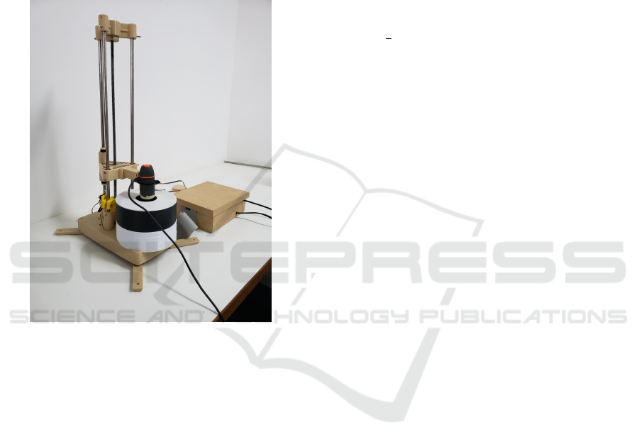
Figure 2: Example of the photometric stereo technique.
The top six images are photos J
(1)
,.. .,J
(6)
of a small
rock/plaster fragment under different lighting conditions.
The images at bottom are is the color-coded surface nor-
mal map
b
N and the intrinsic color map
b
A computed from
the above.
2017).
The two techniques are largely complementary,
because MFS works best when the object’s surface
is discontinuous or has sharp details, wheres PMS
works best when the surface is smooth and fea-
tureless. Therefore, combining the two techniques
promises to yield better reconstructions that what
each method can provide on its own. For this com-
bined approach, one must obtain images J
(k)
i
for n
microscope-to-object distances i = 1,2,. .., n and m
illumination sources k = 1,2, ... ,m. The multifocal
stereo technique is used to obtain a combined sharp
image
e
J
(k)
for each light source k, and a tentative
height map
e
Z
(k)
. Then the photometric stereo tech-
nique is applied to these images, to obtain a single
final height map
b
Z and the intrinsic color map
b
A.
MUFF: A Low-cost Motorized Positioner Developed by Additive Manufacturing to Obtain Multi-focus Images
145
2 THE POSITIONER
One obstacle to this combined multi-
focus/photometric stereo idea is the large number
(mn) of images that must be obtained, which may
reach a hundred or more. In order to alleviate this
problem, we built a simple motorized positioning
device that captures all those images automatically,
varying the distance between the microscope and the
object and the illumination of the same. See Figure 3.
Figure 3: Image of the motorized positioner, with a Cele-
stron Mini Handheld Digital Microscope installed.
The frame is built from 3D-printed plastic ele-
ments and other easily-obtained parts. The stepper
motor (that varies the focus plane) and the LED light
sources (that provide the variable illumination) are
controlled by an Arduino processor and by software
running on a PC. This original design may be a vi-
able alternative to commercial motorized microscope
stands (Silva, 2020).
As seen in Figure 3, the positioner consists of a
stationary supporting frame, a moving carriage that
holds the microscope, and a light box that surrounds
the target object and holds the light sources. The car-
riage is displaced vertically along three fixed guide
rails by a screw, driven by a stepper motor in the
base of the frame. A separate box contains the ded-
icated electronics that control the stepper motor and
the light sources. The electronics and the camera are
connected to the PC by two separate USB cables.
2.1 Operation
Once the positioner is powered up and the operating
software is running, all further user interaction takes
place through a program running on the hosting PC,
that continually displays the image seen by the cam-
era, in real-time.
Specifically, for each job the user commands the
positioner to raise the camera out of the way, places
the target object on the stage inside the light-box, and
commands the positioner to lower the camera until its
focus plane is completely below the visible parts of
the target. That action defines the first focus plane
position z
1
= 0. The user then specifies the number
n of focus positions, the vertical spacing δ between
them, and the number m of illumination conditions.
The program then automatically captures the nm im-
ages J
(k)
i
, looping on k for each camera position i.
Each captured image is displayed by the program, on
a separate window, and saved as a disk file on the PC’s
disk.
3 STRUCTURAL AND
MECHANICAL PARTS
Most structural parts of the frame and carriage
are made of polylactic acid (PLA) thermoplastic,
and were manufactured with a desktop 3D printer
(MAKERBOT REPLICATOR 2). The geometric mod-
els were created by us, using the CAD software sup-
plied with the printer.
Other major structural and mechanical compo-
nents of the system include three vertical steel rails, a
threaded rod and its sliding nut, two clamping springs,
a stepper motor, and six roller bearings (two rotary
and four linear). These parts are held together mostly
by set screws that are self-threaded into the plastic
parts.
3.1 Static Frame
The static frame of the positioner consists of a base
with four extended feet, a lower rail support, an up-
per rail support, a limit switch holder, and three ver-
tical steel columns. See Figure 4. The columns are
smooth solid steel bars, 8mm in diameter, that double
as structural elements and as rails for the carriage.
The lower rail support is a single 3d-printed piece
consisting mainly of three thick-walled tubular rail
holders, with 8 mm internal diameter, connected by
straps in an equilateral triangular prism; and a cubical
motor enclosure, open at the bottom, nestled between
PHOTOPTICS 2022 - 10th International Conference on Photonics, Optics and Laser Technology
146
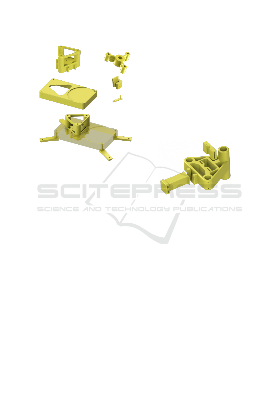
Figure 4: The plastic parts of the frame. Top row: the lower
and upper rail supports. Middle row: the base, limit switch
holder, and one of the four feet. Bottom: how the lower rail
support and the feet are attached to the base.
those tubes. Each rail fits snugly in the vertical hole
of its holder, and is secured by two set screws. The
position and radial orientation of the set screws helps
to ensure that the guides are parallel and equidistant,
in spite of play in the vertical hole and deformation of
the plastic.
The upper rail support too is a single 3D-printed
piece. Its purpose is to hold upper ends of the three
rail guides and of the driving screw in the proper rela-
tive positions. It consists of three thick-walled tubular
guide holders, arranged in an equilateral triangle; and
a central bearing holder. These four sections are held
together by three radial arms. As in the lower sup-
port, each rail is secured to the upper support by two
self-threading set screws.
The base is a hollow rectangular box, measuring
240mm × 140 mm × 33 mm and 3mm thick, fully
open at the bottom. On the top side it has a triangular
opening where the lower support fits, and a circular
depression to hold the light box (see below). Attached
at each corner, on the inside, there is a short vertical
tube that can hold a plastic foot, secured by a screw
from the top of the box. The lower rail support is at-
tached to the base by six screws.
The limit switch holder is a plastic part that is
clamped around one of the guide rails, near the bot-
tom. It holds a microswitch that is positioned and
wired in such a way that the motor turns off imme-
diately when the carriage reaches the lower end of its
range. This detail is meant to protect the motor from
overheating and to prevent the camera from hitting the
target object inside the light box. The vertical position
of the holder can be adjusted according to the camera
dimensions.
3.2 The Carriage
During use, the camera is firmly attached to a plas-
tic carriage that slides on the three rails, driven by
a threaded rod connected to the stepper motor in the
base. It has three separately printed plastic parts: a
chassis, a nut counter-plate, and an interchangeable
camera holder. See Figure 5.
Figure 5: The three plastic parts of the carriage. The bush-
ings, springs, and split nut are not shown.
The chassis, somewhat similar to the lower support,
consists of three vertical tubes connected by straps
in an equilateral triangle. However, the vertical hole
in each tube is wider, and the tube in the back is
more than twice as long as the other two. Two
stainless steel linear motion bearings (type LM08UU,
15mm × 24 mm, with 8 mm internal diameter) are in-
serted in the two tubes at the front and secured by
two set screws each. Two teflon bushings with the
same dimensions are inserted at opposite ends of the
rear tube and each is held by a set screw. All six
set screws are oriented radially. This configuration
of bearings and bushings provides four non-coplanar
points of contact with the rails, that prevent the chas-
sis from tilting in any direction; but still allows the
chassis to slide up and down with low static and dy-
namic friction.
At the center of the chassis there is an opening
with a vertical channel that is meant to hold am M8
hexagonal nut, about 28mm long, split lengthwise
through two opposite faces. In the assembled car-
riage, the halves of the nut are pressed against the
drive screw by a plastic plate with a matching verti-
cal channel, and two steel springs (two 25 mm binder
MUFF: A Low-cost Motorized Positioner Developed by Additive Manufacturing to Obtain Multi-focus Images
147
clips without the handles). One leaf of each spring
is fixed to the pressure plate by a self-threaded screw,
while the other leaf slides down into a slot in the chas-
sis. The pressure from these springs removes any play
that might have existed between the nut and the chas-
sis, thus ensuring that the vertical position of the latter
accurately tracks the rotation of the screw.
The front of the chassis has a pair of slots where
the camera holder can be inserted. The main purpose
of the latter is to position the camera so that its opti-
cal axis matches the axis of the light box. This two-
part design rigidly fixes the camera to the chassis, but
still allows it to be quickly removed for other uses,
or swapped by a different camera, without disassem-
bling the positioner. Also, a camera with different di-
ameter or shape can be accommodated by fabricating
just a new holder (rather than a new chassis).
For the hand-held digital microscope that we used
in out tests, we fabricated a holder (shown in Figure 5)
with an arm about 100 mm long ending with a con-
cave plate. The camera was secured against that plate
by two nylon zip-ties, inserted through a pair of hori-
zontal holes.
3.3 The Driving Mechanism
The mechanism that drives the carriage consists of a
stepper motor, mounted inside the lower support, and
a drive screw that for the full height of the frame, with
plastic connectors at each end. The motor is a NEMA
17 model with 1.1 Nm of torque and 200 steps per
turn. The drive screw is a coarse-threaded M8 (8 mm
diameter, 1.25mm pitch) steel rod bought at a hard-
ware store.
Torque Coupler: Experiments with previous iter-
ations of the device led us to suspect that, because
of the frame’s rigidity, slight misalignments between
the motor axis and the axis of the carriage’s nut were
generating excessive lateral forces greatly increased
friction in the latter, causing slippage in the stepper
motor.
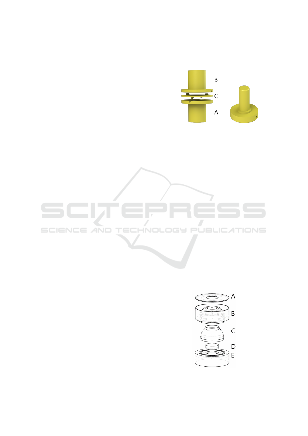
To avoid this potential problem, we designed a
plastic torque coupler to connect the motor to the
drive screw. See Figure 6 (left). It consists of two
“flanges” attached to the motor’s shaft (A) and to the
lower end of the screw (B) by set screws. These two
parts are connected through a transfer disk (C), with
two small teeth on each face. Each pair of teeth slides
along a slots cut into the flat face of the adjacent
flange. The teeth pairs on the two sides are 90 de-
grees offset to each other. Two thin disks of a hard
and smooth PET-like plastic, with slots cut out for the
teeth, are inserted between the three disks to reduce
friction.
Figure 6: Left: the torque/angle coupler between motor and
drive screw. Right: the adapter for the top of the drive screw.
The teeth and slots tightly couple the rotation an-
gle of the screw to that of the motor shaft, and transmit
the full torque of the latter to the former. However,
any misalignment of the two will be accommodated
by lateral shifts of the middle disk, even as the screw
turns, with little lateral stress being felt by either of
them.
Upper Bearing Adapter: The upper end of the
drive screw is inserted in a plastic adapter (Figure 6,
right), that fits into a standard roller bearing that in
turn fits into a cavity on the bottom side of the upper
support.
3.4 The Light-box
The purpose of the light-box is to provide a con-
trolled and repeatable illumination for the target ob-
ject, that is automatically varied as required by the
PMS method. See Figure 7. It consists of a low cylin-
drical platform (E), a specimen stage (D), a light dif-
fuser dome (C), an illumination section (B), and a lid
(A).
Figure 7: Exploded diagram of the light box.
PHOTOPTICS 2022 - 10th International Conference on Photonics, Optics and Laser Technology
148

These parts, printed in white PLA, are not fastened
together, so that the stage can be easily accessed, and
any part of the light box can be excluded, replaced, or
modified if necessary. The platform E is open at the
bottom and fits into a circular depression on top of the
base; its purpose is to ensure that, when the carriage
is at its lowest position, the focus plane of the camera
lies below the target object. The stage D raises the the
target object a bit further so as to improve its illumina-
tion. The diffusing dome C, thin and translucent, may
be used to obtain more uniform and smoother lighting
of the target, if so desired.
The illumination section B is a single plastic part
consisting of a dome that holds the LED light sources
and a cylindrical enclosure that, together with the lid
A, protects their terminals and wiring. The lid has an
opening just wide enough for the camera. The internal
surfaces facing the target are painted matte black.
The device currently has 24 LEDs, arranged in
two rings of 12. A third ring of holes on the dome
could hold another 12 light sources. Each LED
has an independent connection to the electronics box
through a flat 40-wire data cable that exits through a
slot in the back of the section. For greater flexibility,
each LED is held by an individual 3D printed sleeve
(not shown) that is plugged into the corresponding
hole of the light dome. This arrangement can ac-
commodate LEDs of various sizes, holds them more
firmly, and allows their orientation to be individually
adjusted.
4 ELECTRONICS
The main component of the dedicated electronics are
two 10cm × 10 cm printed circuit boards (PCBs) of
the stripboard type, a power supply, and a motor
power drive unit. The electronics circuitry spans also
the 24 LEDS in the light box, the overrun sensing
miscroswitch, and the windings of the stepper motor.
See Figure 8. These components are housed in a low
20cm by 25 cm MDF box, seen in Figure 3.
The central component of the electronics is an Ar-
duino Nano V3 microcontroller (AG, 2017) mounted
on one of the PCBs. All components, except the mo-
tor driver, are powered by the +5V line from the USB
cable, through the Arduino. The rest of the electron-
ics can be conceptually divided into two subsystems:
motion control and lighting control.
4.1 Motion Control
The motion control subsystem applies current pulses
with the proper polarity and timing to the motor wind-
ings. A standard power drive unit (Texas Instruments
DRV8825), fed by a switching power supply type
MS-50-12 (10 A, 12 V, 60 W) is used to convert the bi-
nary 0/5V output signals of the Arduino to the ±12V
voltage and high currents required by the motor, and
also to provide over-current and temperature overload
protection. The Arduino output ports D2, D3, and D4
are connected to the drive’s Enable, Step, and Direc-
tion input pins of the power drive. Outputs 1A, 1B,
2A, and 2B of the drive are connected to the motor
winding terminals.
The motion control circuitry includes the carriage
travel limit sensor, a type MSW-14B micro switch
connected to the Arduino +5V and D10 ports. When
the switch is activated, the Arduino firmware will pre-
vent the motor from turning any further in the direc-
tion that lowers the carriage. This safety feature could
also be used by the controlling script to place the car-
riage at a specified absolute position, independently
of its current state.
4.2 Lighting Control
The light sources currently in use are 24 LEDs, each
producing 10000 mcd of white light with color tem-
perature 5500–6000 K. They are driven by a chain of
three serial-to-parallel demultiplexers (Texas Instru-
ments 74HC595), each with 8 binary 0/+5V outputs.
A 270 Ω resistor limits the current through each LED
to the nominal maximum of 18.5umA. The state of
the LEDs can be changed by the Arduino by sending
24 bits serially through port D6.
5 SOFTWARE
The device’s software consists of a firmware stored
and executed by the Arduino, and a script that runs on
a PC.
5.1 Arduino Firmware
The embedded program muff firmware was writ-
ten in the standard Arduino C-like programming
language. It uses various free libraries, including
the AccelStepper module for stepper motor con-
trol (McCauley, 2017). It receives encoded com-
mands and parameters through the Arduino’s serial
communication (USB) port. Each command consists
of one byte of operation code, and (depending on the
operation) up to four bytes of operand. The avail-
able commands include starting the motor in cruise
(constant speed) mode, up or down, stopping the mo-
tor, raising or lowering the carriage by a specified
MUFF: A Low-cost Motorized Positioner Developed by Additive Manufacturing to Obtain Multi-focus Images
149
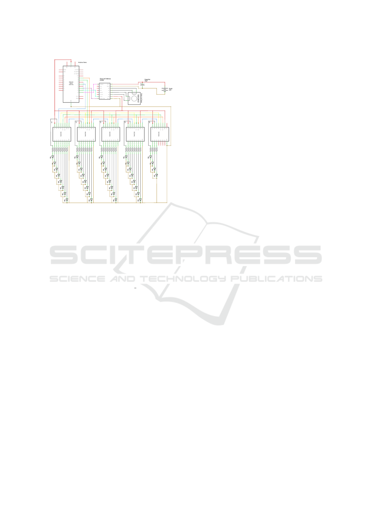
Figure 8: Circuit diagram of the dedicated electronics. Cur-
rently only 24 of the 36 LEDs are installed, thus only the
first three multiplexers are needed.
distance, and turning a specific LED on or off. The
complete list is provided in the software’s documen-
tation (Silva et al., 2019).
5.2 Image Acquisition Script
The image acquisition script muff capture is writ-
ten in the Python language (Silva et al., 2019). It per-
forms two main functions: (a) send to the Arduino the
commands needed to position the camera and turn on
the proper LEDs for each image J
(k)
i
to be acquired;
and (b) capture the image from the camera, saving it
to disk. Currently the script relies on the open-source
software uvccapture for the latter task. These ac-
tions are fully automatic, as described in section 2.1.
The script also lets the user issue individual firmware
commands, e. g. for testing or debugging.
6 CONCLUSIONS
We described a simple device to facilitate capture of
the large number of images required to combine the
techniques of multi-focus and photometric stereo for
millimers-scale objects, by automatically varying the
position of the microscope camera and the sample il-
lumination conditions. The device requires access to
a 3D printer and a few cheap and easily obtainable
parts. The device can position the camera with sub-
millimeter precision and provide up to 24 independent
lighting conditions. These parameters are usually suf-
ficient for good MFS/PMS analysis.
Many possible improvements to the positioner
suggest themselves, such as a more precise driving
mechanism and an angular encoder to remove the risk
of slippage. Indeed, a copy of this device incorporat-
ing these improvements was recently built by Alysson
Mazoni for use at the Geosciences Department of
UNICAMP.
Another very desirable improvement would be a
mechanism to move the speciment stage horizontally,
so that centimeter-scale objects can be automatically
digitized with overlapping MFS/PMS stacks Also, a
mechanism to tilt the stage, even if only by 10-30 de-
grees, would make it possible to combine MFS and
PMS with geometric stereo (GMS), that infers the
third dimension fro multiple images taken from dif-
ferent directions.
ACKNOWLEDGMENTS
This project was partly funded by CNPq (grant
301016/92-5), FAPERJ, UFF (grant PIBINOVA/PDI-
2018), and FAPESP (grant 2013/07699-0).
REFERENCES
AG, A. (2017). Getting started with the ARDUINO NANO.
At https://www.arduino.cc/en/Guide/ArduinoNano.
Bercovici, A., Hadley, A., and Villanueva-Amadoz, U.
(2009). Improving depth of field resolution for pa-
lynological photomicrography. Palaeontologia Elec-
tronica, 12(2):12.
Ciciliato, V. and Chiquito, J. G. (1995). Modelamento do
microsc
´
opio
´
optico como um sistema linear variante
com o deslocamento. In Anais do 13
o
Simp. Bras. de
Telecomunicac¸
˜
oes (SBrT 1995), volume I, pages 258–
263.
Coleman, E. and Jain, R. (1982). Obtaining 3-dimensional
shape of textured and specular surface using four-
source photometry. Computer Graphics and Image
Processing, 18:308–328.
Fernandes, J. L. and Torre
˜
ao, J. R. A. (2010). Shape from
shading through photometric motion. Pattern Anal.
Appl., 13(1):35–58.
Goldman, D. B., Curless, B., Hertzmann, A., and Seitz,
S. M. (2010). Shape and spatially-varying BRDFs
from photometric stereo. IEEE Transactions on Pat-
tern Analysis and Machine Intelligence, 32(6):1060–
1071.
Grossmann, P. (1987). Depth from focus. Pattern Recogni-
tion Letters, 5(1):63–69.
PHOTOPTICS 2022 - 10th International Conference on Photonics, Optics and Laser Technology
150

Lambert, J. H. (1760). Photometria, sive de Mensura et
Gradibus Luminis, Colorum et Umbrae. E. Klett.
Leit
˜
ao, H. C. G., Saracchini, R. F. V., and Stolfi, J.
(2008). Matching photometric observation vectors
with shadows and variable albedo. In Proc. the 21st
Braz. Symp. on Computer Graphics and Image Pro-
cessing (SIBGRAPI 2008), pages 179–186.
McCauley, M. (2017). Accelstepper library for Ar-
duino. At http://www.airspayce.com/mikem/arduino/
AccelStepper/.
Miyamoto, A., Matsuse, H., and Koutaki, G. (2017). Robust
surface reconstruction by design-guided SEM photo-
metric stereo. Measurement Science and Technology,
28(4).
Nayar, S. K. (1989). Shape from focus. Technical Re-
port CMU-RI-TR-89-27, Robotics Institute, Carnegie
Mellon Univ.
Plisson, H. and Zotkina, L. V. (2015). From 2D to 3D at
macro- and microscopic scale in rock art studies. Dig-
ital Applications in Archaeology and Cultural Her-
itage, 2(2–3):102–119.
Qu
´
eau, Y., Lauze, F., and Durou, J.-D. (2015). A L
1
-TV al-
gorithm for robust perspective photometric stereo with
spatially-varying lightings. In Intl. Conf. on Scale
Space and Variational Methods in Computer Vision,
pages 498–510.
Rindfleisch, T. (1966). Photometric method for Lunar to-
pography. Photometric Engineering, 32(3):262–276.
Saracchini, R. F. V., Stolfi, J., and Leit
˜
ao, H. C. G. (2011).
A uniform grid structure to speed up example-based
photometric stereo. IEEE Trans. on Image Processing,
20(12):3495–3507.
Saracchini, R. F. V., Stolfi, J., Leit
˜
ao, H. C. G., Atkinson,
G. A., and Smith, M. L. (2012). A robust multi-scale
integration method to obtain the depth from gradient
maps. Computer Vision and Image Understanding,
116(8):882–895.
Silva, G. L. (2020). Posicionador automatizado para
aplicac¸
˜
ao das t
´
ecnicas de multifocal stereo e photo-
metric stereo para objetos microsc
´
opicos. Final under-
graduate project, Federal Fluminense Univ., Electrical
Eng. Dept. (in Portuguese).
Silva, G. L., Stolfi, J., and Leit
˜
ao, H. C. G. (2019). Muff
positioner - software, diagrams, and stl files. At http:
//www.ic.uff.br/\
∼
hcgl/Muff-index.html.
Thiery, V. and Green, D. I. (2012). The multifocus imaging
technique in petrology. Computers & Geosciences,
45:131 – 138.
Woodham, R. J. (1980). Photometric method for determin-
ing surface orientation from multiple images. Optical
Engineering, 19(1):139–144.
Zamofing, T. and Hugli, H. (2004). Applied multifocus 3D
microscopy. In Proc. SPIE, volume 5265, pages 134–
144.
MUFF: A Low-cost Motorized Positioner Developed by Additive Manufacturing to Obtain Multi-focus Images
151
