A Specification Language and a Modeling Tool for Spatial User
Interaction
Khadidja Chaoui
1 a
, Sabrina Bouzidi-Hassini
1 b
and Yacine Bellik
2 c
, Chabane Karasad
1
and Abderrahmane Hamzaoui
1
1
Laboratoire des M
´
ethodes de Conception de Syst
`
emes (LMCS), Ecole nationale Sup
´
erieure d’Informatique (ESI),
BP, 68M Oued-Smar,16270 Alger, Algeria
2
Laboratoire Interdisciplinaire des Sciences du Num
´
erique, Universit
´
e Paris-Saclay, Orsay, France
Keywords:
Spatial User Interface, Specification Language, Modeling, Simulation.
Abstract:
Spatial user interaction result from considering spatial attributes (localization, orientation. . . ) of entities or
spatial relations between them (distance, relative position. . . ) to trigger system functions. Recently, more
and more spatial interactive applications exist in daily life (parking radar in cars, automatic doors in super-
markets and building...). Such interfaces offer more natural and intuitive interactions due to their facility to
use or downright their transparency. According to our literature review on spatial interaction works, we no-
ticed that most of them focused on the desire to demonstrate the relevance of the interaction paradigm itself.
Unfortunately, only few works were conducted to standardize necessary concepts for the spatial interface de-
velopment such as specification languages, modeling or simulation tools. These letters facilitate designers
work and contribute to the democratization of this kind of interaction. In this context, we present in this pa-
per, a modeling language called SUIL (Spatial User Interaction Language) and a framework for modeling and
simulating spatial interfaces called SIMSIT (Spatial Interfaces Modeling and SImulation Tool).
1 INTRODUCTION
Ambient environments are connected worlds where
sensors and actuators are continuously used to make
inhabitants’ lives more comfortable. Spatial user in-
teraction represents an interesting interaction model
to explore in such environments providing thereby
rich and natural interactions. It refers to interactions
that result from considering spatial attributes of phys-
ical objects and/or users or spatial relations between
them to trigger system functions (Chaoui et al., 2020).
For example, the Guiding Wheelchairs is a spatial in-
teractive application proposed by (Favey et al., 2016)
to secure movements of a wheelchair using distance
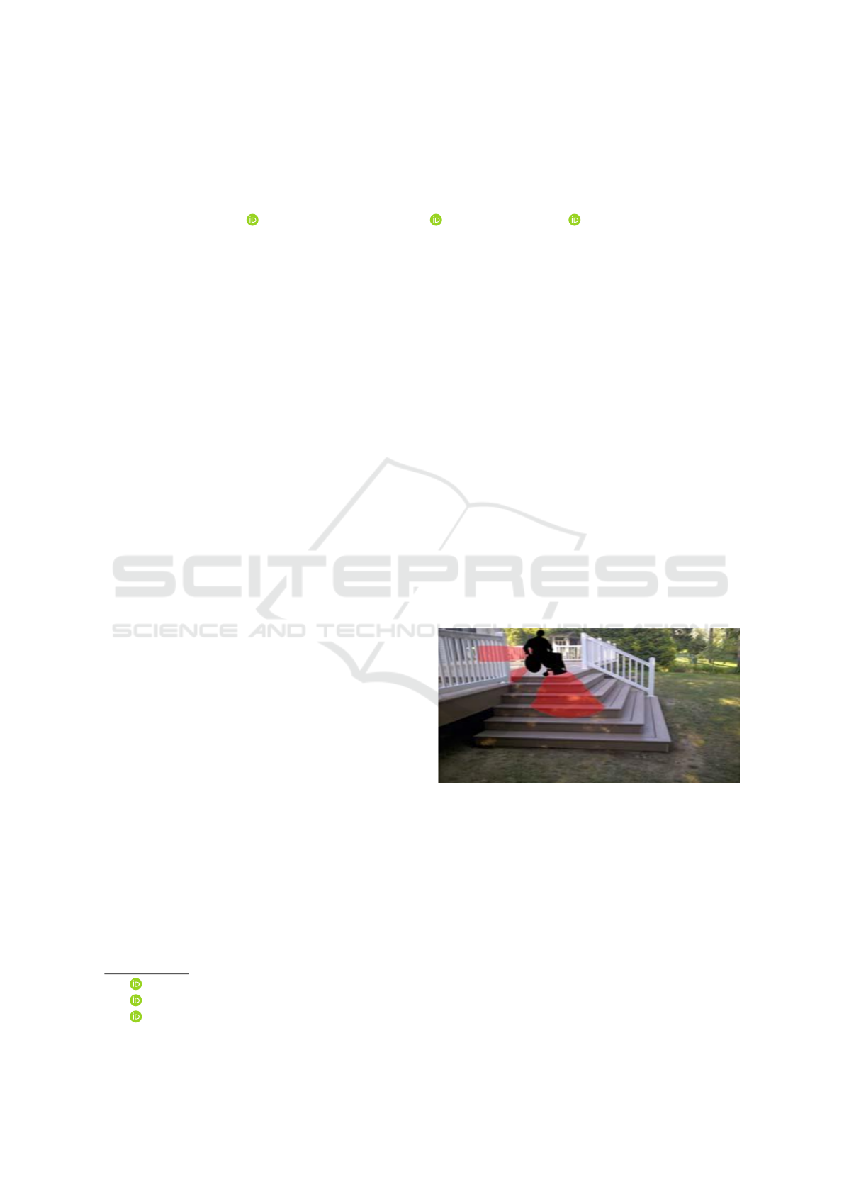
information. Figure 1 illustrates the case where the
chair detects a stairs presence. Thus, the user is
warned of a dangerous situation by sound and vibra-
tion signals.
Many works (academic and marketed) have been
proposed. They demonstrated the relevance of the
spatial user interaction paradigm. Nevertheless, only
a
https://orcid.org/0000-0001-6877-6858
b
https://orcid.org/0000-0002-0466-7190
c
https://orcid.org/0000-0003-0920-3843
Figure 1: Stairs detection (Favey et al., 2016).
few of them were conducted to standardize the nec-
essary concepts or to propose facilitator tools for the
development process of spatial interfaces.
Usually, user interface design tools refer to meth-
ods, languages, or software used for interface design.
They can significantly facilitate the expression of de-
sign ideas. Different design tools exist for graph-
ical (Vos et al., 2018), touch (Khandkar and Mau-
rer, 2010) and multimodal interfaces (Elouali et al.,
2014). However, concerning spatial interfaces design
and development, there is a lack of tools that might
help designers and developers in their task. Despite
Chaoui, K., Bouzidi-Hassini, S., Bellik, Y., Karasad, C. and Hamzaoui, A.
A Specification Language and a Modeling Tool for Spatial User Interaction.
DOI: 10.5220/0010905100003124
In Proceedings of the 17th International Joint Conference on Computer Vision, Imaging and Computer Graphics Theory and Applications (VISIGRAPP 2022) - Volume 2: HUCAPP, pages
225-232
ISBN: 978-989-758-555-5; ISSN: 2184-4321
Copyright
c
2022 by SCITEPRESS – Science and Technology Publications, Lda. All rights reserved
225
the existence of a few tools for proxemic interaction
(which represent a particular point of view of spatial
user interaction, where distance plays a fundamental
role), they remain intended for very specific applica-
tions.
In order to analyze works on tools that support the
design and implementation of spatial interfaces, we
made a comparative table (Table 1) of the works cited
below based on two criteria: Tool type and Genericity.
(Perez et al., 2020) proposed a proxemic interac-
tion modeling tool based on a DSL (Domain Specific
Language). The latter is composed of symbols and
formal notations representing proxemic environment
concepts which are: Entity, Cyber Physical System,
Identity, Proxemic Zone, Proxemic Environment and
Action. From a graphical model, the tool creates an
XML schema used to generate executable code. In
(Marquardt et al., 2011) the authors presented a prox-
imic toolkit that enables prototyping proxemic inter-
action. It consists of a collection library conceived
in a component-oriented architecture and considers
the proxemic variables between people, objects, and
devices. The toolkit involves four main components:
(1) Proximity Toolkit server, (2) Tracking plugin mod-
ules, (3) Visual monitoring tool and (4) Application
programming interface. Another proxemic designers’
tool for prototyping ubicomp space with proxemic in-
teractions is presented in (Kim et al., 2016). It is built
using software and modeling materials, such as: Pho-
toshop, Lego and paper. Interactions can be defined
with photoshop based on proxemic variables. The
tool uses an augmented reality projection for minia-
tures to enable tangible interactions and dynamic rep-
resentations. A hidden marker sticker and a camera-
projector system enable the unobtrusive integration
of digital images on the physical miniature. Spi-
derEyes (Dostal et al., 2014) is a system and toolkit
for designing attention and proximity aware collabo-
rative scenarios around large wall-sized displays us-
ing information visualization pipeline that can be ex-
tended to incorporate proxemic interactions. Authors
in (Chulpongsatorn et al., 2020) explored a design
for information visualization based on distance. It
describes three properties (boundedness, connected-
ness and cardinality) and five design patterns (subdi-
vision, particalization, peculiarization, multiplication
and nesting) that might be considered in design.
According to the previous study, we noticed a lack
of generic approaches and tools capable of handling
the process of building applications supporting spatial
user interaction. In addition, existing works do not
take into account all the possibilities of spatial inter-
action. It treats only proxemic interactions as shown
above which are mainly based on distance. Moreover,
Table 1: Summary of designing tools for proximic user in-
teraction.
Reference Tool type Genericity
(Perez et al.,
2020)
Modeling
language and
prototyping
environment
Generic
(Marquardt
et al., 2011)
Prototyping
environment
For specific
use
(Kim et al.,
2016)
Prototyping
environment
For specific
use
(Dostal et al.,
2014)
Prototyping
environment
For specific
use
(Chulpongsatorn
et al., 2020)
Prototyping
environment
For specific
use
proposed tools target the prototyping of specific ap-
plications, except the recent research of (Perez et al.,
2020) which came forward to define a language for
proxemic interaction specification.
In order to respond to these shortcomings, we in-
troduce in this paper SUIL (Spatial User Interaction
Language) and SIMSIT (Spatial Interface Modeling
and SImulation Tool) which are respectively a model-
ing language and a modeling & simulating framework
for spatial interfaces. The remainder of this article is
structured as follows: Section 2 describes The SUIL
modeling language, and section 3 presents the SIM-
SIT tool. Section 4 provides a conclusion and per-
spectives for future works.
2 SUIL: A SPATIAL USER
INTERACTION LANGUAGE
We propose a language for modeling spatial user in-
terface called SUIL. It enables designers to specify
spatial interfaces with maximum expressivity which
means that it provides for them all needed concepts
to construct the spatial interactions they want to im-
plement. Figure 2 presents the abstract syntax of the
SUIL language.
2.1 Coordinate System
The coordinate system represents the absolute refer-
ence in the given physical space (an ambient room, a
smart house, etc.) that serves to determine absolute
locations and orientations of objects and/or users.
In the following, we will refer to each object and/or
user involved in spatial interactions by the term Spin
(SPatial INteractor). It will be introduced later (in
section 3.3).
HUCAPP 2022 - 6th International Conference on Human Computer Interaction Theory and Applications
226
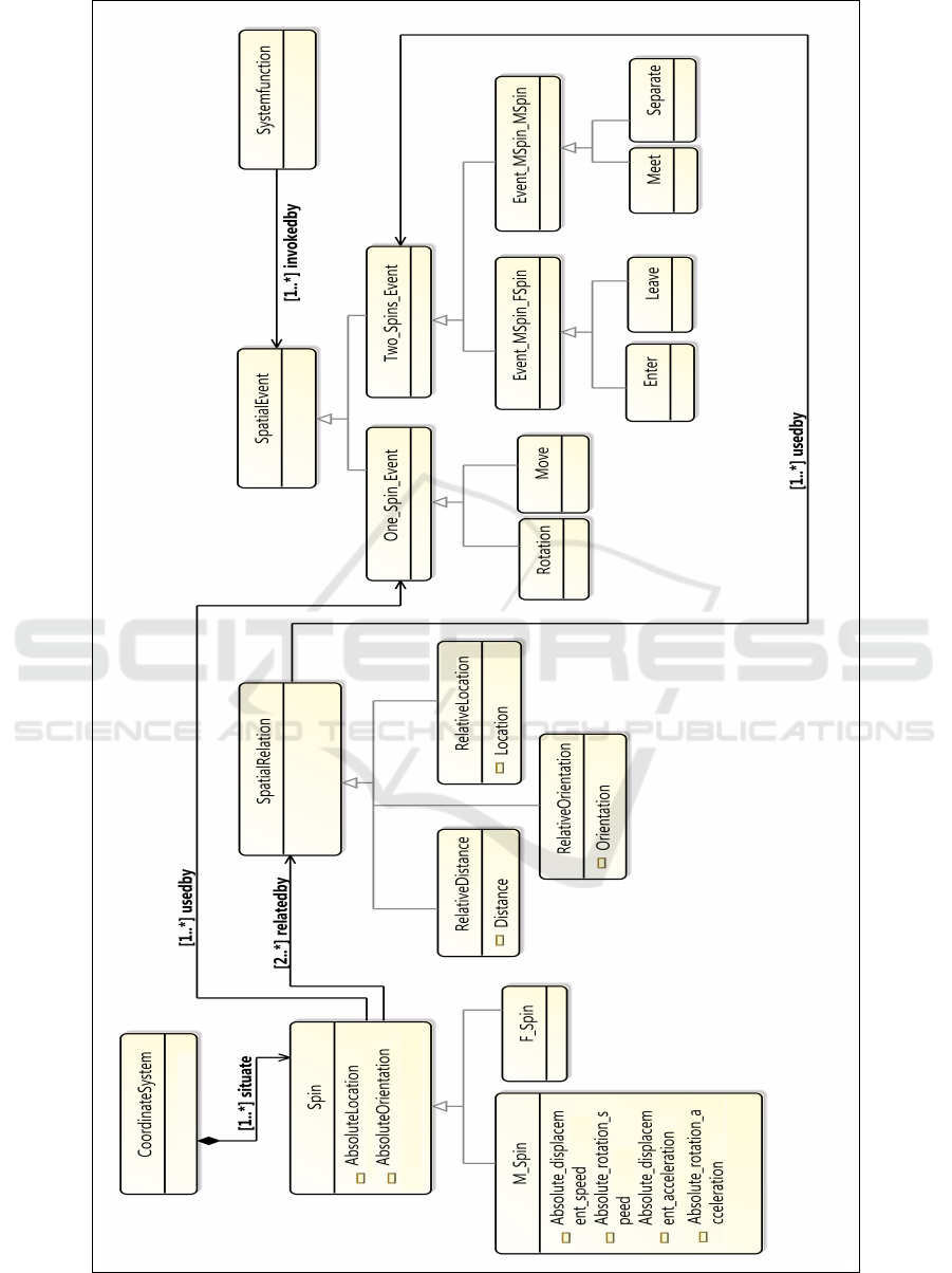
Figure 2: Global view of the SUIL metamodel.
A Specification Language and a Modeling Tool for Spatial User Interaction
227
2.2 Spatial Attributes
Spatial attributes represent spatial characteristics of
the spins. All spins are characterized by their abso-
lute location and absolute orientation in the physical
space regarding the given coordinate system. As we
will see, other attributes can be considered according
to the spin types.
2.3 Spatial Interactor (Spin)
The concept of Spatial interactor (Spin) refers to the
considered entities of the environment. These can be
physical tangible objects, the user’s body or parts of it
for which the system tracks spatial attribute changes
to invoke system functions. We distinguish two types
of spins: fixed spins (F-spin) and mobile spins (M-
spin).
• Fixed Spatial Interactor (F-Spin): An F-spin
is supposed to keep the same absolute location
and the same absolute orientation in the physical
space all the time. It can be, for instance, a piece
of furniture, but it can also refer to some space
areas that the designer wants to define and use as
special regions offering specific services. Thus,
speed and acceleration of a F-spin are always
equal to 0.
• Mobile Spatial Interactor (M-Spin): M-spins con-
cern entities that can move by themselves in the
physical space (such as users and robots) or can be
moved by someone else (such as tangible objects
manipulated by users or robots). Besides abso-
lute location and orientation, these entities can be
characterized by additional attributes due to their
ability to move or to be moved (Table 2). Actually,
a spin is moving if its absolute location and/or
its absolute orientation changes. Therefore, ab-
solute displacement speed and absolute rotation
speed (regarding the coordinate system) can be
considered to characterize movement speed. No-
tate that, M-spins can have their speed and accel-
eration equal to 0 at some moments but can have
them different from 0 at other moments. Thus, the
speed variation can be characterized by absolute
displacement acceleration, and absolute rotation
acceleration.
2.4 Spatial Relations
A spatial relation refers to a spatial link between two
spins. It provides information about a spin A in regard
to another spin B. We identify three spatial relations
Table 2: Spatial attributes according to Spin’s type.
Spin’s
type
Spatial attributes
Absolute location
F-Spin Absolute orientation
Absolute location
M-Spin Absolute orientation
Absolute displacement speed
Absolute rotation speed
Absolute displacement accelera-
tion
Absolute rotation acceleration
relative location, relative distance and relative orien-
tation.
• Relative Location: determines location of a
spin with respect to another reference spin. For
instance, a spin A can be at the left, right, bottom,
top, in front or behind another spin B.
• Relative Distance: represents the amount of space
between two spins. One may think that relative
distance and relative location are redundant.
In fact, they are not. Relative distance can be
calculated from relative location but not the
opposite because for a given distance, multiple
locations are possible (imagine different points at
the surface of a sphere: they are all at the same
distance from the center of the sphere but not
at the same location). Some spatial interactions
are based only on distance while others require
precise location.
• Relative Orientation: it consists in indicating in
which orientation a spin is placed with respect to
another reference spin. For instance, a user can
face a screen or has his back to the screen.
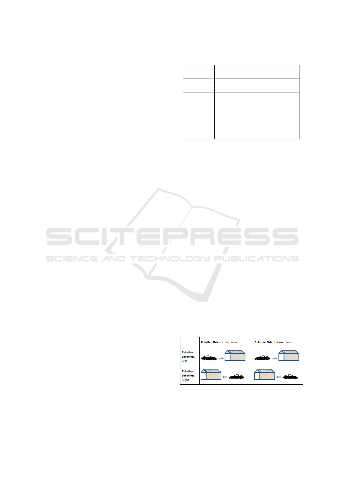
Figure 3 presents an example from real life ex-
plaining the difference between relative location and
relative orientation.
Figure 3: Relative orientation and relative location of a car
in regard to a parking garage.
HUCAPP 2022 - 6th International Conference on Human Computer Interaction Theory and Applications
228

2.5 Trigger Condition
A trigger condition represents the condition required
to be able to invoke a system function. It can be com-
posed of one or many spatial relations connected by
logical operators.
2.6 System Functions
System functions represent the system’s triggered ser-
vices. Each verified trigger condition must invoke a
system function that meets a user’s need.
2.7 Spatial Event
A spatial event interprets the spatial state change of
one or more spins. It is characterized by attributes,
conditions and variants as explained below.
2.7.1 Spatial Event Attributes
Represent spatial properties and spatial relation val-
ues. According to these values, many event instances
(variants) may be considered thus giving the opportu-
nity for designers to specify many associated system
functions.
2.7.2 Spatial Event Condition
Represents a collection of spatial event attributes re-
lated by logical operators. The event is validated
only when the condition is verified. Events are val-
idated after the expiration of a certain (configurable)
time during which the spin remains in the same state.
This allows avoiding the generation of extra unwanted
events. For instance, if a system function is associated
with a 45
◦
rotation event and another one with a 90
◦
rotation event, this will avoid the consideration of the
45
◦
event every time the user turns the spin from 0
◦
to 90
◦
. In addition, in order to facilitate user interac-
tions, we propose to validate events when the required
event’s property belongs to an interval of values rather
than to be an exact value. This reduces the handling
error rate and decreases the interaction time by avoid-
ing the users to carry out their actions with great pre-
cision.
2.7.3 Spatial Event Variants
For each event’s type, several instances can be identi-
fied according to considered event conditions and at-
tributes. Some examples are presented in the follow-
ing section for more explanation.
2.7.4 Spatial Event Types
According to considered spins’ number, we can iden-
tify two categories of events: One-Spin events and
Two-Spins events. Events involving more than two
spins can be expressed using logical operators com-
bined with two-spin events
a. One-spin Events
It is possible to trigger system functions by manip-
ulating only one spin. We identify in this case two
events “Move” and “Rotation”. Notate that these
events concern only the M-spin due to its mobility.
a.1 Rotation: a Rotation event occurs when the
absolute orientation of the M-spin changes along one
of the three axes at least (i.e the X-axis, the Y-axis
and the Z-axis). This leads to identifying three variant
events (Rotation X-axis, Rotation Y-axis, Rotation
Z-axis). If the designer also considers absolute
Speed and absolute acceleration, two other variants
may be identified which are M-Spin Abs Speed and
M-Spin Abs Acceleration.
a.2 Move: a Move occurs when the absolute location
of the M-spin changes.
b. Two-Spin Events
When several spins are available in the system, events
involving two spins may occur. Depending on the
spin types, we can distinguish events related to the
couple (F-spin, M-spin) and others related to the
couple (Mspin, M-spin).
b.1 F-Spin/M-Spin Events.
In this case, the first spin is fixed and the second
one is mobile. We define two events: “Enter” and
“Leave”. For each of them, different variants may be
considered according to the used spatial attributes,
spatial relations, and their values.
b.1.1 Enter: an Enter event occurs when the M-spin
is getting close to the F-spin. According to the used
spatial attributes and relations, many variants can be
identified.
b.1.2 Leave: a Leave event occurs when the M-spin
moves away from the F-spin. According to the used
spatial attributes and relations, many variants can
be identified. Figure 4 shows different variants of
Enter and Leave events depending on location and
orientation.
A Specification Language and a Modeling Tool for Spatial User Interaction
229
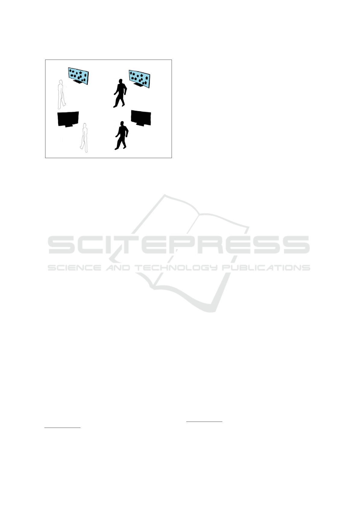
Figure 4: Different variants of Enter and Leave events de-
pending on location and orientation.
b.2 M-spin/M-spin Events.
In the case of two M-spins, we identify two events
“Meet” and “Separate”. At their turn, they may gen-
erate variants according to the used spatial attributes,
relations, and their values. Note that since some re-
lations are not commutative such as Relative Loca-
tion and Relative Orientation, the order of the two M-
Spins, in the event condition, is important (the first
one relatively to the second one).
b.2.1 Meet: a Meet event occurs when the two
M-spins get close to each other i.e., distance between
the two M-spins becomes greater or equal than a
fixed minimum distance and lower than or equal to
a fixed maximum distance. This gives an indication
that some movement is occurring. Relative distance,
location, speed and orientation when they are addi-
tionally used, generate many variants.
b.2.2 Separate: a Separate event occurs when the two
M-spins move away from each other i.e., distance be-
tween the M-spins becomes outside a fixed distance
interval.
3 SIMSIT: TOOL SUPPORT FOR
SUIL
SIMSIT (Spatial Interface Modeling and SImulation
Tool) is a framework for modeling and simulating
spatial interfaces. Through SIMSIT we can first, ma-
nipulate graphical representation of SUIL concepts to
specify spatial user interfaces. Then, the modeled in-
terface can be generated to provide a simulation of the
spatial interface through a web page. Visual studio
1
1
https://visualstudio.microsoft.com/fr/
and C#
2
language were used for the development of
SIMSIT.
3.1 Modeling
This module allows designers to specify the spatial
interface design using the SUIL concepts. It consists
of four parts: (a) dashboard,(b) workspace, (b) tool’s
palette and (d) control panel (Figure 5).
3.1.1 Dashboard
The dashboard contains statistics on graphical con-
cepts created by the user in the workspace (Figure 5-
A).
3.1.2 Workspace
The workspace consists in an area where the user
models its spatial user interface using the tool’s
palette (Figure 5- B).
3.1.3 Tool’s Palette
Contains necessary concepts for modeling. These
concepts are added to the model by simple drag and
drop operations (Figure 5-C). The palette is divided
into several sections which provides the concepts
used in the SUIL language. For instance:
-Section 1 is dedicated to the ”Spin” concept.
It provides the two types of spins: F-Spin and M-Spin.
-Section 2 is dedicated to the ”Spatial Relation”
concept. It allows specifying the type of spatial
relation.
-Section 3 is dedicated to the ”Events” concept. It
provides different types of events.
-Section 4 is dedicated to the concept ”System
function”. It provides identified system functions.
-Section 5 is dedicated to the ”Coordinate system”
concept. It provides physical sensors.
3.1.4 Control Panel
The control panel displays the characteristics of the
SUIL concepts (name, type, etc.) and the character-
istics of the graphical interface (height, width, etc.)
(Figure 5-D).
2
https://docs.microsoft.com/en-us/dotnet/csharp/tour-
of-csharp/
HUCAPP 2022 - 6th International Conference on Human Computer Interaction Theory and Applications
230
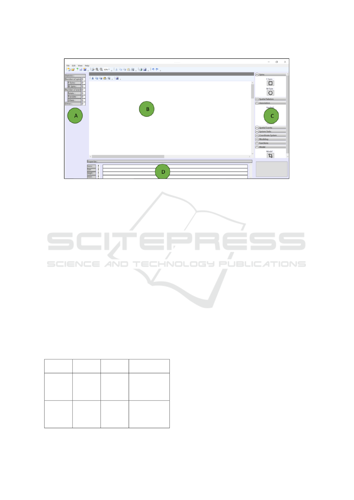
Figure 5: The main window of SIMST.
3.2 Simulation
The simulation allows to test and validate the con-
structed model. The simulation is done using a sim-
ulation website. The latter recovers the data stored in
the XML file generated by the previous module. It
interprets and displays them. Manipulations are done
using a control panel provided in the web page.
3.3 Example of Applications Modeled
and Simulated with SIMSIT
To check SIMSIT framework, we present in this sec-
tion a case study. It consists of manipulating the VLC
media player software through simulated spatial user
interactions into a graphical interface. Before starting
the modeling and the simulation, we need to define
system functions, spins and spatial attributes that will
be used in the example (Table 3). We choose to use
only one M-spin illustrated by a cube that can be ma-
nipulated using the mouse.
Table 3: Elements for the example control application.
System
function
Spin Event
type
Used spatial
attribute
Pause
VLC
M-spin Rotation Absolute
Orientation
Angle ∈
[40
◦
,50
◦
]
Play
VLC
M-spin Rotation Absolute
Orientation
Angle ∈
[85
◦
,95
◦
]
The Modeling process is carried out into two
parts: (a) modeling the graphical interface and (b)
modeling of the functional model.
(a) The graphical interface corresponds to the
interface that simulates the execution scene. In the
example (Figure 6-a), a cube (represents the M-spin)
is manipulated by the user to launch system functions.
(b) The functional model is composed of the cube (M-
spin) events that invoke system functionalities (Figure
6-b). After modeling, the result is saved in an XML.
We proceed after that to the using the simulation
website and the XML file. Figure 7 shows the simu-
lation of the example modeled in the previous section.
4 CONCLUSION
The presented work proposes a language and a frame-
work for modeling spatial user interaction. Literature
analysis showed that existing works aim to demon-
strate the relevance of the spatial interaction technique
rather than to provide tools and methods to specify it
in a generic and reusable way. Hence, we noticed a
lack of tools supporting the process of realizing spa-
tial interfaces, starting from the design phase until
the development and deployment ones. Based on the
aforementioned concerns, we introduced SUIL (Spa-
tial User Interaction Language), a modeling language
and SIMSIT (Spatial Interface Modeling and SImu-
lation Tool), a tool for modeling and simulating spa-
tial interfaces. A case study using proposed tool was
A Specification Language and a Modeling Tool for Spatial User Interaction
231
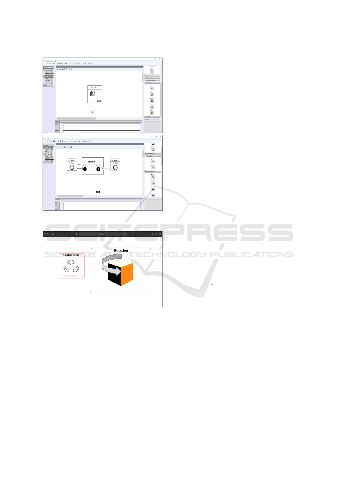
Figure 6: Modeling the the graphical interface (a) and func-
tional model of the VLC control application (b).
Figure 7: Simulation of the example control application.
also presented. In future work, we aim first to use
the SUIL language for developing an application in a
real ambient environment. Then, we aim to conduct
user studies with the developed applications to pro-
vide guidelines and recommendations concerning the
design of spatial interfaces.
REFERENCES
Chaoui, K., Bouzidi-Hassini, S., and Bellik, Y. (2020). To-
wards a specification language for spatial user interac-
tion. In Symposium on Spatial User Interaction, pages
1–2.
Chulpongsatorn, N., Yu, J., and Knudsen, S. (2020). Ex-
ploring design opportunities for visually congruent
proxemics in information visualization: A design
space.
Dostal, J., Hinrichs, U., Kristensson, P. O., and Quigley,
A. (2014). Spidereyes: designing attention-and
proximity-aware collaborative interfaces for wall-
sized displays. In Proceedings of the 19th interna-
tional conference on Intelligent User Interfaces, pages
143–152.
Elouali, N., Le Pallec, X., Rouillard, J., and Tarby, J.-
C. (2014). Mimic: leveraging sensor-based interac-
tions in multimodal mobile applications. In CHI’14
Extended Abstracts on Human Factors in Computing
Systems, pages 2323–2328.
Favey, C., Villanueva, J., Zogaghi, A., Jordan, L., Des-
sailly, E., Bellik, Y., and Farcy, R. (2016). Guiding
wheelchairs by active optical profilometry, for persons
with multiple disabilities, modelling. Measurement
and Control C International Journal, (2):111–119.
Khandkar, S. H. and Maurer, F. (2010). A domain spe-
cific language to define gestures for multi-touch ap-
plications. In Proceedings of the 10th Workshop on
Domain-Specific Modeling, pages 1–6.
Kim, H.-J., Kim, J.-W., and Nam, T.-J. (2016). Ministudio:
Designers’ tool for prototyping ubicomp space with
interactive miniature. In Proceedings of the 2016 CHI
Conference on Human Factors in Computing Systems,
pages 213–224.
Marquardt, N., Diaz-Marino, R., Boring, S., and Greenberg,
S. (2011). The proximity toolkit: prototyping prox-
emic interactions in ubiquitous computing ecologies.
In Proceedings of the 24th annual ACM symposium on
User interface software and technology, pages 315–
326.
Perez, P., Roose, P., Dalmau, M., Cardinale, Y., Masson,
D., and Couture, N. (2020). Mod
´
elisation graphique
des environnements prox
´
emiques bas
´
ee sur un dsl. In
INFORSID 2020, pages 99–14. dblp.
Vos, J., Chin, S., Gao, W., Weaver, J., and Iverson, D.
(2018). Using scene builder to create a user interface.
In Pro JavaFX 9, pages 129–191. Springer.
HUCAPP 2022 - 6th International Conference on Human Computer Interaction Theory and Applications
232
