Software Architecture Mining from Source Code
with Dependency Graph Clustering and Visualization
Anthony Savidis
1,2
and Crystallia Savaki
2
1
Institute of Computer Science, FORTH, Heraklion, Crete, Greece
2
Department of Computer Science, University of Crete, Greece
Keywords: Reverse Engineering, Architecture Mining, Source Code Analysis, Architecture Visualization.
Abstract: The software architecture represents an important asset, constituting a shared vision amongst the software
engineers of the various system components. Good architectures link to modular design, with loose coupling
and cohesion defining which operations are grouped together to form a modular architectural entity.
Modularity is achieved by practice otherwise we may observe a mismatch where the source code diverges
from the primary architectural vision. In fact, class groups with dense interdependencies denote the real
architectural entities as derived and implied directly from source code. In this work, we created a tool to assist
in mining the actual system architecture. We extract all sorts of dependencies by processing all source files,
and then using graph clustering, we capture and interactively visualize strongly coupled class groups with
configurable weights. We also support forced clustering on namespaces, packages and folders.
1 INTRODUCTION
In software engineering there are no concrete
engineering protocols prescribing the transformation
of architectures into thoroughly implemented
systems. Overall, it is mainly experience, practices,
guidelines, directives, patterns, and generally
engineering knowledge, driving the process of coding
a system, starting from an initial architecture. Once
the initial software system version is developed and
published, even the assessment of the degree of
conformance between the produced source code and
the intended architecture remains a big challenge.
Usually, this is a second priority since the emphasis
in the production process is on feature delivery,
system integration and defect resolution, all under a
usually very strict time schedule.
Thus, once all are satisfied that the original
requirements are met and that the system is reliable
enough to be rolled out, the potential architecture-
code mismatch is not even put on the table as an issue
deserving examination. In fact, we are not aware of
any experience report or a post-development activity
spending some effort to effectively investigate this
topic. But even when there is no start-up distance
between the code and its underlying architecture,
once a system evolves and new features are inserted,
the symptom of architecture decay will likely soon
appear. Such architecture decay may seriously restrict
the chances for reuse at the macroscopic scale, since
component-level reuse is very sensitive to the
underlying implementation-specific dependencies.
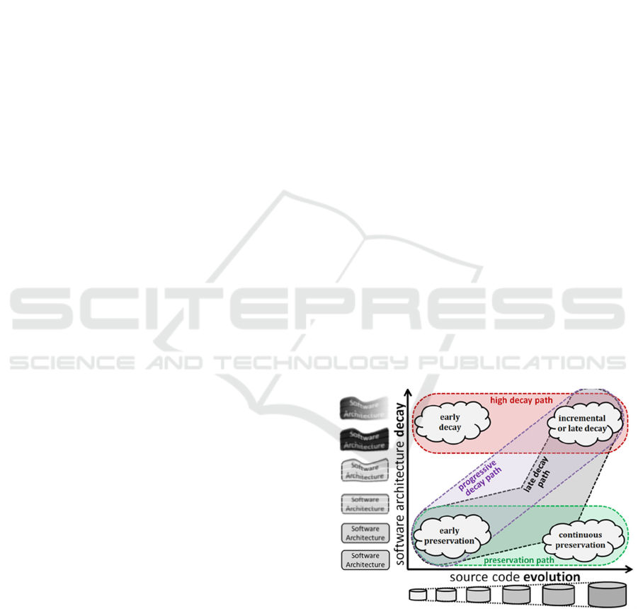
Figure 1: Typical cases of architecture decay denoting that
erosion is usually proportional to code increase.
Architecture decay or erosion (Terra et al., 2012)
is observed when there is a considerable divergence
between the actual system architecture, as implied
from the source code and its inherent component
structure and dependencies, and the assumed software
Savidis, A. and Savaki, C.
Software Architecture Mining from Source Code with Dependency Graph Cluster ing and Visualization.
DOI: 10.5220/0010896800003124
In Proceedings of the 17th International Joint Conference on Computer Vision, Imaging and Computer Graphics Theory and Applications (VISIGRAPP 2022) - Volume 3: IVAPP, pages
179-186
ISBN: 978-989-758-555-5; ISSN: 2184-4321
Copyright
c
2022 by SCITEPRESS – Science and Technology Publications, Lda. All rights reserved
179

architecture communicated inside the development
team. Under Figure 1, the notion of architecture
degeneration is illustrated. Only basic cases are
shown, since decay may appear with alternative
patterns and variations due to successive evolution
rounds.
One reason explaining the decay phenomenon is
software entropy (Hunt and Thomas, 1999) linking to
imperfect implementation practices and coding habits
commonly denoted as code smells (Tufano et al,
2015). Accumulated insertions of new low-quality
source code tend to propagate to all aspects of the
software system, including its software architecture
and how precisely or clearly the conceptual
components map to code. Erosion is also linked to the
entropy phenomenon, observed as an uncontrolled
increase of dependencies, leading to chaotic tight
coupling, making components depend on each other
at various levels and in numerous ways. However,
erosion is not exclusively a symptom of size
escalation through poor quality code. It may well
occur even with high-quality code extensions, once
the inherent effort to revisit the architecture is not
invested.
Overall, good architecture design rents its roots to
modular design, with loose coupling and cohesion
defining when operations are grouped together to
form a modular architectural entity. Clearly, the role
of dependencies in reverse engineering (Kienle and
Moeller, 2010) and in software architecture was set
before, as a basis to recover architectures (de Silva
and Balasubramaniam, 2012) and to reveal the reality
underneath the code as source dependencies imply
respective architectural dependencies. In fact, based
on modular design foundations, a strong and precise
implementation directive can be derived:
For any two given components A, B:
dep (A,B) in architecture
dep (A,B) in code
2 RELATED WORK
Earlier work has tried to address the erosion problem
by enabling architectures to evolve (Breivold et al.,
2012), (Ford et al., 2019) in a way aligned with
changing requirements. Such methods cannot
guarantee an alignment between architecture and
code, even if modelling (like UML) and formal logic
are combined (Barnes et al., 2014), since source code
growth itself does not follow strictly formal models.
Various tools to statically analyze source code exist,
usually extracting dependencies and metrics, like
Sourcetrail (Sourcetrail tool, 2021) and Understand
(Understand tool, 2021). Rigi (Kienle Moeller, 2010)
is a notable system enabling interactively navigate in
dependency graphs, but is mostly a tool for inspecting
code relationships, not supporting architecture
recovery. An earlier effort in (Rakic et al., 2014)
proposed a comprehensive set of language-
independent dependencies that we also adopted.
However, we also had to introduce parameterized
generic types in order to handle the complicated
dependencies emerging due to the template type
system of the C++ language.
All existing tools offer browsing in dependency
graphs, helping to track code dependencies at a very
low-level. Clearly, they do not provide some
macroscopic picture, but give an alternative graph-
like look on the source code itself. Compared to such
previous work, we exploit code dependencies to
reveal the actual architecture components of a system.
To identify tightly connected groups, representing
likely components, we use and assess various graph
clustering algorithms.
3 IMPLEMENTATION
The primary goal of this work is to examine
systematically the potential of dependency-oriented
graph clustering for architecture recovery. In this
context, we decided to develop a software tool to
support our aims, meeting two key requirements: (i)
can extract all relationships of interest directly from
the source code; and (ii) supports alternative
clustering algorithms, while offering a rich set of
interactive configurations for the visualizer. Then,
another important target was the investigation of the
types of common dependency motifs appearing in
clustered graphs, and their association with design
properties and architectural semantics.
In our tool, we supported C++ source code mainly
due to the challenges implied by pointers, multiple-
inheritance, templates (with partial and full
specialization), lambda functions, and automatic type
inference. Nevertheless, the contribution is not
dependent on C++ and is along the following lines:
We classify dependencies in four basic types,
namely deploys, contains, inherits and template
(i.e. generic parametric type) while introducing
weighting and filtering options based on repeated
presence of the same dependency.
We apply graph-clustering algorithms, combined
with optional ad-hoc clustering by package,
folder and namespace, to capture tightly coupled
IVAPP 2022 - 13th International Conference on Information Visualization Theory and Applications
180
class-groups, via an extensible set of algorithms.
Such intrinsically strongly coupled class groups
will effectively denote the real architectural plan
behind the source code.
We also explore and suggest potential dependency
patterns that may expose higher-level truths regarding
the underlying implementation architecture, and we
discuss a few patterns we initially identified: base,
utility, main, unused, divorce and pair. This
essentially leads to another notion of patterns, besides
architecture patterns (Buschmann et al., 1996),
according to the way class-level dependencies are
topologically formed, at a macroscopic level.
3.1 System Overview
Our system consists of two main components: (i) the
backend, producing a global dependency graph by
parsing all source files of an application system,
implemented in C++ on top of the Clang compiler-
frontend toolchain; and (ii) the frontend, computing
and rendering graph clusters, while supporting
alternative clustering algorithms and numerous
configuration options for visualizing graphs and
dependencies (see Figure 2).
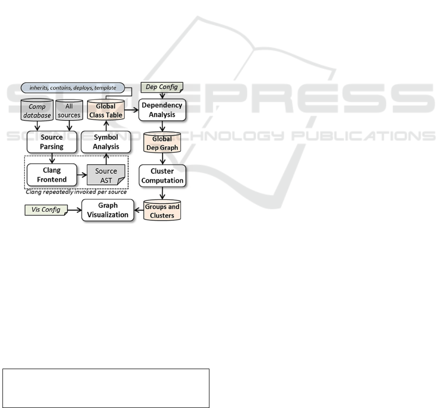
Figure 2: Overview of the miner software architecture.
The global class-table enumerates all classes,
including templates, and keeps a global (full system,
across files and packages) symbol table. Method
signatures, class fields, method invocations, type and
use of local variables, etc., are all kept in detail, and are
used to compute every class-level dependency. The
main goal of this system is reconstruction of the actual
architecture, directly from source code, by computing,
analyzing, and clustering dependencies. This idea
relies on modular design and the following statement:
In a modular architecture, any two given
classes which belong to different components,
must be loosely-coupled
Following this statement strongly coupled classes
reside in the same component. This is essentially a
precondition for the mapping of modular
architectures to code, and we consider it as the key
criterion to recover the real architecture behind the
source code. Next, we briefly explain the key
processing phases of our system.
3.2 Dependency Analysis
Such analysis is performed after syntactic and
semantic analysis, by examining class dependencies
that result from inheritance, member fields, friend
classes and methods and class nesting. In addition, all
object types involved in a class implementation are
checked, including method arguments, local variables
and all member access expressions using objects of
another class. Therefore, the dependencies between
classes maybe divided in two categories: (i) primary
dependencies, due to inheritance, field definitions,
method signatures, and friends, visible in class
declarations; and (ii) secondary dependencies,
arising from all object uses in the implementation of
methods, visible only in class definitions. In our
miner, we handle such dependencies similarly, but we
also allow the assignment of different weights via the
interactive configuration tools.
3.2.1 Ignoring Unwanted Symbols
During dependency analysis, exhaustive parsing is
carried out, involving all system source files and
headers. This may result in millions of lines of code,
even for small-scale systems, due to the use of third-
party libraries, which, however, do not contribute to
the architecture recovery process. For this reason, we
allow define namespaces and folders whose hosted
classes are excluded from dependency analysis, and
are thus not inserted in the global dependency graph.
Typical cases for exclusion are the C++ std
namespace and folders for platform-specific libraries
or open source sub-systems.
3.2.2 Handling Templates
The template system is an advanced mechanism in
C++ to implement libraries of generic classes and
functions, and relates to parameterized types and
generics in other languages. Such idioms and
constructs are heavily used in large-scale code, while
due to type parameterization and specialization they
make inherent dependencies very hard for humans to
manually inspect and locate.
Software Architecture Mining from Source Code with Dependency Graph Clustering and Visualization
181

Figure 3: Computing all dependencies involving template
classes (in grey), template full specializations (in orange),
partial template specializations (in green), and their link to
non-template classes (in blue, no border).
Effectively, it is crucial to track all dependencies
caused by templates, otherwise, only a partial picture
of the underlying class relationships is revealed.
Under Figure 3, we outline representative scenarios
of dependencies occurring when template base
classes and template inheritors are defined, which are
all fully captured in our system.
3.3 Clustering and Visualization
Initially, the graph is flat containing only atomic
nodes, while we use grouping nodes into so-called
super nodes to impose structure and derive
components by clustering. The miner is extensible in
terms of clustering algorithms, supporting as output
primary clusters and optionally nested ones, if the
latter are also output by the used algorithm. We
require that algorithms can handle weights, while it is
desirable to support directed edges or multi-level
clustering. We have already implemented and
installed three algorithms, chosen also because of
their varying behavior, namely Louvain (Blondel et
al., 2008), Infomap (Rosvall et al., 2009) and Layered
Label Propagation (Raghavan et al., 2007).
In Figure 3, we show the output, following the
application of the Infomap algorithm, on the C++
implementation of the Super Mario video game,
including in the source code base the entire game
engine and all accompanying utilities. It should be
noted that the rest algorithms also gave satisfactory
results, but not so close to what the game developers
considered to better match their own understanding
of their system’s architecture.
As depicted in Figure 3 (red outlined rectangles), a
few components are misplaced, meaning they we may
relocate them inside another component reasonably,
that is without breaking the dependency-based
grouping semantics of modular design. The problem
here is that the graph clustering algorithms are quite
rigid, emphasizing stronger inner dependencies for the
nodes of the same cluster. Therefore, classes with just
a few outgoing dependencies are likely assigned to the
cluster having most edges towards them, which can be
a false positive in terms of architecture semantics. We
discuss more on this in our findings as part the next
section.
Besides visual parameters, the active clustering
algorithm can be changed during visualization,
without requiring any reparsing and reanalysis of the
source code files. This is possible because the global
dependency graph is stored separately and contains
all detailed dependencies and class meta-data needed
for clustering to work.
This makes visual inspection very fast and more
useful, enabling developers examine alternative
groupings and architectural views, as produced by the
various algorithms. However, it is important that they
are aware of the characteristics of the clustering
approach of each such algorithm, regarding the use of
dependencies, edges weights and general grouping
strategy. This way, they can assess which method
better fits their study.
4 CASE STUDIES
We processed a few systems in our case study,
supplying also as input the miner itself (the part in
C++). In Figure 4, one view for an open source
version of the Super Mario platform game is provided
- the visualizer offers configurations allowing
alternative depictions, including the dynamic
switching of the clustering algorithm.
During our case study we examined various
visualization alternatives and analyzed the
architectural semantics behind the various grouping
formations and patterns we observed. Very quickly, a
few common structures appeared, with an
interpretation matching the documented role of the
respective source elements in their system and the
module interrelationships. Hence, we tentatively
defined the notion of dependency patterns as
connectivity styles in class dependency graphs that
say something valid about the roles and relationships
of the involved classes.
IVAPP 2022 - 13th International Conference on Information Visualization Theory and Applications
182
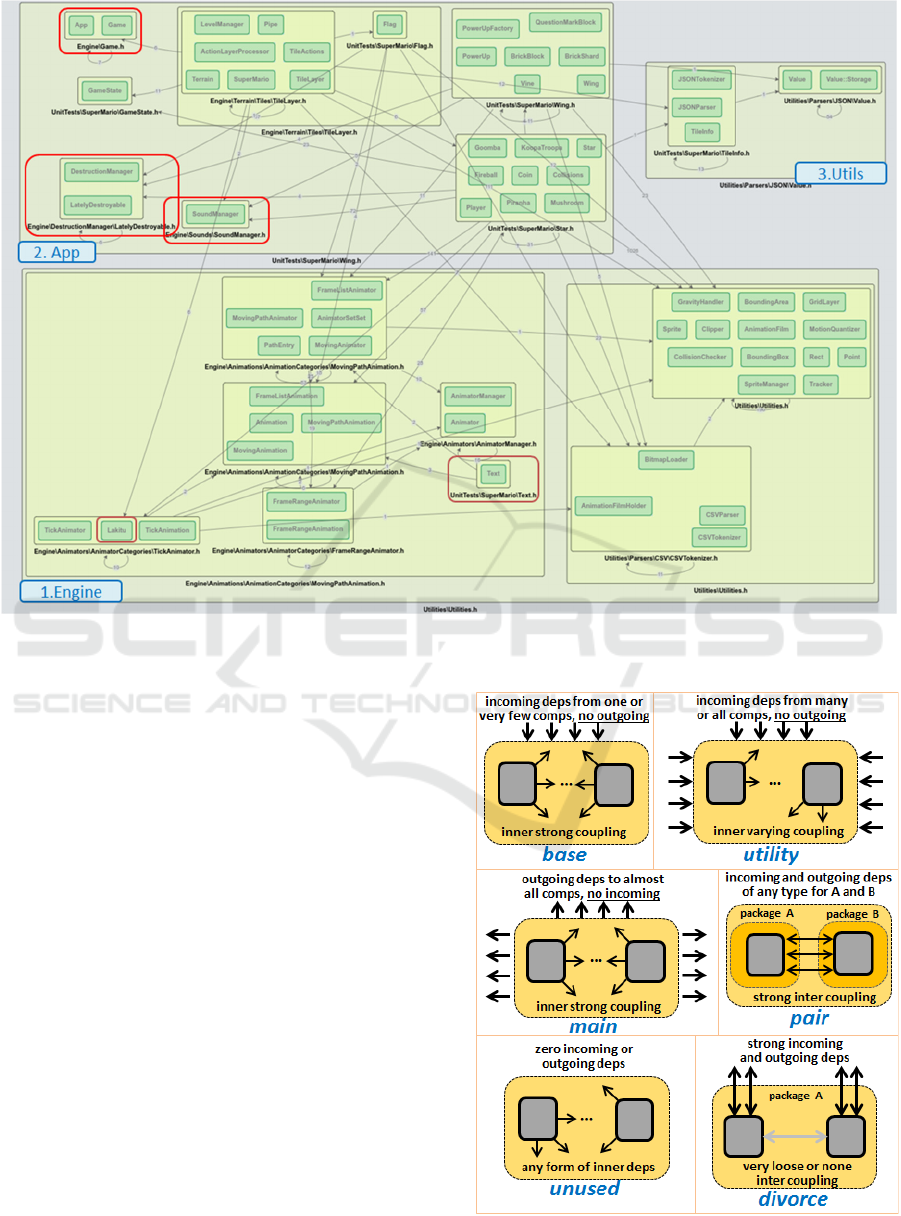
Figure 4: Visualizing dependencies and clustering to capture the components of Super Mario game (with Infomap) – all top-
level components are well captured (engine, app and utilities), but some sub-components are misplaced (red outlined).
Such information, due to erosion, may be absent
in the currently assumed architecture. When
combined with clustering, the dependency patterns
can reveal more aspects of the actual architecture, and
even suggest source code repackaging.
This notion of dependency patterns is different
from architecture patterns (Taylor et al., 2009), the
latter emerged in analogy to software patterns as
common architecture recipes for structuring parts of
a system implementation. In our study, as shown
under Figure 5, we identified a number of dependency
patterns that we verified in the examined systems.
After careful analysis and many discussions with the
developers of the original systems, it was clear that
erosion is not only a matter of architecture image
mismatch. Instead, it may also signify inconsistent
module packaging, wrong file grouping and even
class misnaming.
Thus, once the real dependencies and respective
clusters are revealed, more macroscopic source code
refactoring and updates may be required to reflect the
emerging relationships and modules. We briefly
discuss below the few dependency patterns we
identified, also depicted under Figure 5:
Figure 5: Architectural dependency patterns.
Software Architecture Mining from Source Code with Dependency Graph Clustering and Visualization
183
Base: cluster with considerable inner links, lack
of any outgoing dependencies, and usually all
incoming dependencies originated from just one
or a couple clusters;
Utility: cluster with a lot of incoming
dependencies, from many classes across clusters,
in some cases from all, with commonly loose
inner coupling (not many intra edges) and
encompassing a set of many distinct and
independent classes;
Main: cluster with a very distinctive role, that
tends to depend on various classes from all the rest
of clusters, while being characterized by relatively
strong inner coupling;
Pair: cluster encompassing classes that are very
strongly coupled, however, originally residing in
different packages or namespaces (likely
components), something possibly suggesting
they should be placed into a single component;
Unused: cluster looking in the graph as an
isolated island, with no edges to or from other
classes or clusters, and with various forms and
intensities of inner dependencies;
Divorce: cluster that happens to group together
classes that initially belong to the same package
or namespace, which however seem to be clearly
decoupled, while having many incoming or
outgoing links - when they share no external
neighbors the divorce is even more evident.
We also noticed the appearance of some of these
patterns in multilevel clustering, inside sub-clusters.
More specifically, we observed that the Main
dependency pattern inside a cluster indicated a likely
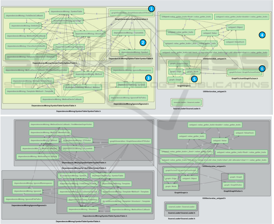
Figure 6: Visualization output (clustered components showing likely architecture as directly derived from the code) by
applying our miner tool on its own source code base – use of multi-level Infomap algorithm (top) and Louven (bottom).
IVAPP 2022 - 13th International Conference on Information Visualization Theory and Applications
184
Façade design pattern implementation over the
classes belonging to the rest of the sub-clusters. This
is topologically reasonable, since the Main
component represents the core application logic built
on top of the rest of the classes, in analogy to the way
Façade implements a custom adapted interface for the
collective functionality over a number of classes.
Also, we may observe in certain situations the
presence of the Utility pattern inside an entire cluster,
with outgoing links from all inner classes towards a
specific group. This will almost always imply that
such common utility functionality is quite specific
and local to role of the component, likely explaining
no incoming edges from external classes.
4.1 Processing the Miner Source Code
In Figure 6 (top part) the outcome of the Infomap
algorithm for multi-level clustering (with nested
components) is depicted. As observed, the graph is
divided into three basic groups. Since sourceLoader
(bottom-right isolated node) has no interrelationship
with the other nodes it is be ignored for the rest of the
discussion. Studying the main two groups, we
observe that they represent the class data extraction
of the symbol analysis (left group) and dependency
graph composition of dependency analysis (right
group), bot being primary components of our
architecture.
We further observe that these two components are
independent, with no connecting edges between their
inner elements. The link between them is the
GraphGenerationSTVisitor node (shown with label
1). Overall, this result is very valid and reflects the
sequential flow of the system, very similar to
compiler architectures in terms of dataflow. We
might expect this node to be part of the graph
generation cluster (dependency analysis), but it seems
that data traversing dependencies have attracted it to
the data extraction group, which is still acceptable.
Furthermore, the inner group structure is relative to
assumption because it adheres to the above-
mentioned namespace categorization. It should be
noted that no configuration over dependency type
weights is used. It is remarkable that the Infomap
algorithm divides nodes with only inner
interconnections and incoming edges (labelled 2, 3, 4,
5) and those with only outer dependencies (labelled
1, 6) into separate clusters, treating them as
independent components. As a result, it maintains the
highest relative density of edges within the clusters.
Our explanation for the very small distance between
the designed arch and the recovered one from the
source code of the tool is due to the lack of any actual
system versions. Normally, a typical lifecycle of a
system counts many updates, implying a significant
amount of time for code evolution. It is actually after
such update rounds that most architectural deviations
begin to appear. Finally in Figure 6 (bottom part) the
outcome of the Louvain algorithm for multi-level
nested clustering is shown. At first glance, the graph
appears to be divided into four major classes and
groups. When we examine them more closely, we can
see that the cluster on the right represents the
dependency analysis component, as it also arises in
the Infomap output, with only some minor differences
in the structure of its inner groups. We also note that
the logical component of the symbol analysis is now
split into two subgroups, with the method-related
nodes effectively placed in a separate group. Clearly,
we can accept that the two outputs actually match and
express the same architectural structure.
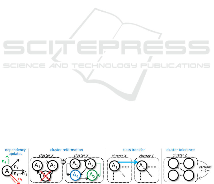
4.2 Comparing Version Visualisations
Finally, we briefly studied the effect of applying the
miner on successive code versions and comparing the
output structurally (manually, not with algorithms).
This led us to an initial set of scenarios of Figure 7
that we intend further explore, since linking structural
changes with architectural semantics, such as
component tolerance, is valuable information on how
code evolution eventually affected the underlying
architecture.
In particular, from an early manual analysis of the
results in one of the examined systems, we noticed
that before class transfer, a number of well-defined
and very common dependency changes occurred in
the cluster due to various sequential small code
updates. We also verified that in all cases where we
observed a utility dependency pattern, it
Figure 7: Possible update patterns when comparing the output dependency graphs for major successive code versions.
Software Architecture Mining from Source Code with Dependency Graph Clustering and Visualization
185

tended to remain almost intact across and unaffected
code versions, and thus tolerate code changes.
5 CONCLUSIONS
We developed a tool for architecture recovery directly
from source code and carried out a study on the results
produced by using different working configurations.
Our method tracks source code dependencies,
prepares incrementally, by parsing and analysing all
source files, a global dependency graph, and then
applies clustering algorithms to compute likely
architectural modules. The foundation of our
approach is modularity theory and the essential
criterial underpinning modular design, requiring
loose coupling across components, with intensive
dependencies appearing only as intra-component
links. We observed good results when switching and
playing with alternative clustering functions and
parameters.
Finally, we also explored two new ideas: (i) the
notion of dependency patterns, where we identified a
few cases frequently occurring in our study; and (ii)
correlations of clustering output resulting from
successive code versions to capture potential trends in
the software evolution process.
Although our focus on the second topic was more
limited in time, we believe that version-specific
clustered graphs collectively possess a lot of valuable
information for further versioning analysis.
REFERENCES
Terra, R., M.T. Valente, K. Czarnecki, R.S. Bigonha
(2012). Recommending Refactorings to Reverse
Software Architecture Erosion. In Proceedings of the
16th European Conference on Software Maintenance
and Reengineering, IEEE, March 2012, pp 335–340
ISO/IEC/IEEE 42010:2011. Systems and software
engineering — Architecture description
de Silva, L., Balasubramaniam, D. (2012). Controlling
software architecture erosion: a survey. Journal of
Systems and Software. 85 (1): 132–151.
Hunt, Andrew; Thomas, David (1999). The Pragmatic
Programmer, Addison Wesley, ISBN 0-201-61622-X.
Tamburri, D. A., Kazman, R. (2018). General methods for
software architecture recovery: a potential approach
and its evaluation. Empirical Software Engineering, 23
(4), June 2018, Springer
Tufano, Michele; Palomba, Fabio; Bavota, Gabriele;
Oliveto, Rocco; Di Penta, Massimiliano; De Lucia,
Andrea; Poshyvanyk, Denys (2015). When and Why
Your Code Starts to Smell Bad. In 2015 IEEE/ACM
37th IEEE International Conference on Software
Engineering. pp 403–414
Ducasse, S., Pollet, D. (2009). Software Architecture
Reconstruction: A Process-Oriented Taxonomy. In
IEEE Transactions on Software Engineering,
September 2009, 35(4)
Johnson, R., Opdyke, W. (1993). Refactoring and
Aggregation. In proceedings of the First International
Symposium on Object Technologies for Advanced
Software, Springer LNCS Vol. 742, pp 264-278
Buschmann F., Meunier R., Rohnert H., Sommerlad P., Stal
M. (1996). Pattern-Oriented Software Architecture: A
System of Patterns. John Wiley & Sons.
Breivold, H. P., Crnkovic, I., Larssona, M. (2012). Software
architecture evolution through evolvability analysis.
Elsevier Journal of Systems and Software, 85(11), pp
2574-2592
Ford, N., Kua, P., Parsons, R. (2019). Building
Evolutionary Architectures: Support Constant Change.
2nd Release. O'Reilly Media.
Barnes, J., Garlan, G., Schmerl, B. R. (2014). Evolution
styles: foundations and models for software
architecture evolution. Software Systems Modelling
13(2), pp 649-678
Rakic, G., Budimac, , Z., Ivanovic, M. (2014). A language-
independent approach to the extraction of dependencies
between source code entities. Elsevier Journal
Information and Software Technology, Vol 56, pp
1268-1288
Sourcetrail – The open-source cross-platform source
explorer. The Sourcetrail Development Team.
https://www.sourcetrail.com/. Accessed June 2021.
Assunção, W., Lopez-Herrejon, R., Linsbauer, L., Vergilio,
S., Egyed, A. (2017). Multi-objective reverse
engineering of variability-safe feature models based on
code dependencies of system variants. Springer
Empirical Software Engineering, Vo 22, pp 1763–1794
Kienle, H. M., Moeller, H. A. (2010). Rigi-An environment
for software reverse engineering, exploration,
visualization, and redocumentation. Science of Comp.
Programming, 75(4), pp 247-263.
Understand - Take Control of Your Code. Scientific
Toolworks, Inc. https://www.scitools.com/. Accessed
June 2021.
Blondel, V. D., Guillaume, J.-L., Lambiotte, R., Lefebvre,
E. (2008). Fast unfolding of communities in large
networks. Journal of Statistical Mechanics: Theory and
Experiment, 2008, P10008.
Rosvall, M., Axelsson, D. & Bergstrom, C. T. (2009). The
map equation. https://arxiv.org/abs/0906.1405
Raghavan, U., Albert, R., Kumara, S. (2007). Near linear
time algorithm to detect community structures in large-
scale networks. Physical review. Phys. Rev. E 76,
036106.
Taylor, R.N., Medvidović, N., Dashofy, E. M. (2009).
Software architecture: Foundations, Theory and
Practice. Wiley.
IVAPP 2022 - 13th International Conference on Information Visualization Theory and Applications
186
