
Camera Pose Estimation using Human Head Pose Estimation
Robert Fischer
1
, Michael H
¨
odlmoser
1
and Margrit Gelautz
2 a
1
emotion3D GmbH, Vienna, Austria
2
Visual Computing and Human-Centered Technology, TU Wien, Vienna, Austria
Keywords:
Camera Networks, Camera Pose Estimation, Head Pose Estimation, Extrinsic Calibration.
Abstract:
This paper presents a novel framework for camera pose estimation using the human head as a calibration
object. The proposed approach enables extrinsic calibration based on 2D input images (RGB and/or NIR),
without any need for additional calibration objects or depth information. The method can be used for single
cameras or multi-camera networks. For estimating the human head pose, we rely on a deep learning based
2D human facial landmark detector and fit a 3D head model to estimate the 3D human head pose. The paper
demonstrates the feasibility of this novel approach and shows its performance on both synthetic and real multi-
camera data. We compare our calibration procedure to a traditional checkerboard calibration technique and
calculate calibration errors between camera pairs. Additionally, we examine the robustness to varying input
parameters, such as simulated people with different skin tone and gender, head models, and variations in
camera positions. We expect our method to be useful in various application domains including automotive in-
cabin monitoring, where the flexibility and ease of handling the calibration procedure are often more important
than very high accuracy.
1 INTRODUCTION
Registering the position and orientation of cameras
relative to each other is called camera pose estimation
or extrinsic calibration. It is a common task in 3D
computer vision, where main application fields cover
the areas of robotics as well as automotive and virtual
reality (Pajdla and Hlav
´
ac, 1998; Xu et al., 2021). In
order to calculate the camera pose, some known cali-
bration object is commonly used to find proper inter-
relationships (Gua et al., 2015). Prevalent objects are
boards with a checkerboard pattern or a circle grid
pattern on a flat surface (Zhang, 2000; Abad et al.,
2004). Unfortunately, such patterns are not always
easily applicable in different scenes and use cases.
In this paper, we present a novel approach to calcu-
late the extrinsics of multiple cameras using the hu-
man head as a calibration pattern. Figure 1 shows
the application of our camera pose estimation tech-
nique in an automobile cockpit. Given one or mul-
tiple synchronized cameras observing a human head
and one projection for each camera of such a head
allows the extraction of 2D landmarks for each pro-
jection, which, in combination with a given 3D head
model, allows the extraction of both a 3D head pose
a
https://orcid.org/0000-0002-9476-0865
and all camera poses. The presented method is there-
fore especially suited for camera setups where human
heads are visible or analyzed, such as environments
within a cockpit of a vehicle, train or plane, where
one or more cameras are focusing on the occupants.
By using an underlying 3D head model, the method
does not need depth information as an input and in-
stead only requires 2D input images, such as RGB
or NIR images. Our approach is useful for applica-
tions where an ease of calibration is more important
than a high calibration accuracy. Such applications in-
clude region-based attention monitoring (Lamia and
Moshiul, 2019), robot attention tracking (Stiefelha-
gen et al., 2001) and automated shops (Gross, 2021).
It is infeasible to require users of such systems to cal-
ibrate the cameras extrinsically beforehand.
2 RELATED WORK
Using the human head as a calibration target is a novel
approach for multi-camera pose estimation. Tradi-
tionally, a planar calibration pattern has been applied
for the task of multi-camera pose estimation. Ini-
tially, (Zhang, 1999) proposes to use a plane from
unknown orientations. Later, (Zhang, 2000) propose
Fischer, R., Hödlmoser, M. and Gelautz, M.
Camera Pose Estimation using Human Head Pose Estimation.
DOI: 10.5220/0010879400003124
In Proceedings of the 17th International Joint Conference on Computer Vision, Imaging and Computer Graphics Theory and Applications (VISIGRAPP 2022) - Volume 4: VISAPP, pages
877-886
ISBN: 978-989-758-555-5; ISSN: 2184-4321
Copyright
c
2022 by SCITEPRESS – Science and Technology Publications, Lda. All rights reserved
877
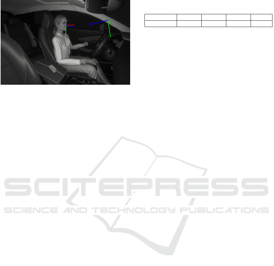
Figure 1: Our camera pose estimation framework performs
a multi-camera pose estimation based purely on head pose
estimation.
to use a planar checkerboard-like calibration pattern.
(Abad et al., 2004) adapt this approach to rely on con-
centric cycles. (Ansar and Daniilidis, 2002) propose
an algorithm for camera pose estimation supporting
both point and line correspondences. (Manolis and
Xenophon, 2013) shows a model-based pose estima-
tion technique using general rigid 3D models can be
applied as well. (Camposeco et al., 2018) aim to solve
camera pose estimation by leveraging structure-based
(2D-3D) and structure-less (2D-2D) correspondences.
(N
¨
oll et al., 2010) provide an overview of camera pose
estimation techniques.
Human head pose estimation is the task of esti-
mating the 3D pose of a head in a given input image
(Shao et al., 2020). In some earlier works, head pose
estimation was performed by using manifolds (Chen
et al., 2003; Balasubramanian et al., 2007; Raytchev
et al., 2004). Promising results were also achieved by
applying random forests on RGB and depth images
(z. Qiao and Dai, 2013; Fanelli et al., 2011; Fanelli
et al., 2013; Huang et al., 2010; Valle et al., 2016; Li
et al., 2010). Deep learning based approaches have
also shown to be successful for RGB and depth im-
ages (Venturelli et al., 2016; Ruiz et al., 2018; Wu
et al., 2018; Liu et al., 2016; Patacchiola and Can-
gelosi, 2017).
The need for multi-camera pose estimation in the
absence of a dedicated calibration object is common
in 3D computer vision. (Bleser et al., 2006) use a
CAD model to reconstruct the camera pose. The ap-
proach of (Rodrigues et al., 2010) exploits planar mir-
ror reflections in the scene. (H
¨
odlmoser et al., 2011)
rely on pedestrians on a zebra crossing to estimate the
camera pose. Related to our approach are (Puwein
et al., 2014), (Kosuke et al., 2018) and (Moliner et al.,
2020). However, their methods use the whole hu-
man body pose, instead of only the head pose, to cal-
culate the extrinsics of all cameras relative to each
Table 1: Runtimes of head pose estimation on ARM Cortex
A57 (2.035 GHz) per camera.
No. Cores: 1 2 3 4
Runtime 25.1 ms 14.9 ms 12.1 ms 9.9 ms
other. Consequently, these approaches usually require
the full human body to be visible by the cameras.
Such set-ups are convenient in common surveillance
or studio-like environments, but less well suited for
scenarios where the human head is the focus of the
camera setup. Another fundamental difference is that
these approaches use the joint positions as point cor-
respondences, whereas our work relies on pure esti-
mation of a human’s head pose.
3 CAMERA POSE ESTIMATION
Our multi-camera calibration method performs head
pose estimation for each camera independently and
simultaneously, resulting in a set of transformations
from a shared head coordinate system into the respec-
tive camera coordinate systems and vice versa. In this
section, we explain the overall calibration workflow
for multi-camera pose estimation using 3D head pose
estimation.
3.1 General Workflow
Multi-camera pose estimation is a common problem
in 3D computer vision and can be time-consuming to
perform. Traditionally, it is first necessary to phys-
ically prepare some calibration object, for example
print an adequate checkerboard, and then validate that
the calibration object satisfies certain conditions, such
as being rigid and unbendable. Afterwards, it is usu-
ally necessary to set up and parametrize the calibra-
tion pipeline. The calibration itself can then be exe-
cuted by placing the calibration object, capturing the
calibration data and finally performing the calibration.
In contrast, our approach only requires a single person
to be present in the scene in order to calculate the head
pose based camera pose estimation. Calculating the
human head pose is computationally more expensive
than localizing the checkerboard pattern. We counter-
act this problem by running the head pose estimation
algorithm on a graphical processing unit (GPU), re-
sulting in comparable execution times. Table 1 gives
an overview of the runtimes on different numbers of
cores.
VISAPP 2022 - 17th International Conference on Computer Vision Theory and Applications
878

3.2 Camera Pose Estimation using 3D
Human Head Pose Estimation
Assuming the camera intrinsics are known, the first
step in our novel camera pose estimation pipeline is
the extraction of a human head pose. In principle,
any head pose estimator that returns a proper orien-
tation and translation for a human head can be used
for our method. For the case of cockpits in vehicles,
we can usually assume that the cameras have an un-
obstructed view of the occupant’s face, which allows
for the usage of facial landmarks for head pose esti-
mation. In our work, we first detect the face using
an off-the-shelf face detector and then extract the fa-
cial landmarks in the captured 2D image from each
camera. We choose a convolutional neural network
(CNN) architecture to obtain the facial landmarks us-
ing convolutional pose machines (CPMs) based on
(Wei et al., 2016) trained with faces from the COCO
2014 dataset (T.-Y. Lin et al., 2014). The authors of
(Wei et al., 2016) provide a prediction framework for
learning image features and image-dependent spatial
models with long-range dependencies between image
features. In the original paper, the authors applied
CPMs for human pose estimation, but as shown in
Section 4, this can be extended to extracting facial
landmarks as well.
We then use the extracted facial landmarks to fit
a 3D-head model using iterative Perspective-n-Point
(PnP) on the estimated facial landmarks (Lu et al.,
2000). We first consider the case of a single camera.
Using PnP, we get a transformation from the head co-
ordinate system to the camera coordinate system. The
accuracy of the PnP-step depends on two main fac-
tors. Firstly, the quality of the facial landmarks. For
example, the nose can usually be predicted relatively
precisely. The same might not be the case for the ears,
as they are often covered by hair or the orientation of
the head itself. Luckily, the CPM architecture we im-
plemented can often still estimate a reasonable loca-
tion for such facial landmarks. Secondly, the degree
to which the 3D-head model actually matches the pre-
dicted facial landmarks is also important for the qual-
ity of the final head pose. We assume a predefined
3D-head model for each detection, which might lead
to more inaccuracy if the recorded head does not fit
the assumption. Nevertheless, we found in our exper-
iments that a generic 3D-head model still is applicable
for a broad range of different human heads.
In the following we discuss how to construct the
multi-camera network. Figure 2 visualizes the multi-
camera setup with the corresponding coordinate sys-
tems and transformations.
Figure 2: Schematic overview of the camera network
with the corresponding camera coordinate systems (CCS),
a shared coordinate system (SCS), and the corresponding
transformations between them.
We define a head pose as a translation and orien-
tation between a camera coordinate system’s origin to
the head’s coordinate system’s origin. To construct a
transformation T from the head pose translation t and
rotation matrix R, which transforms from the head co-
ordinate system into the camera coordinate system,
we use the convention of Equation 1. We define a
transformation T as a 4x3 matrix in which a 3x3 ma-
trix R defines the rotation and a 1x3 matrix t specifies
the translation. Equation 2 shows how to perform the
inverse transformation.
T = [R|t] (1)
T
−1
= [R
T
| − R
T
∗t] (2)
In Figure 3, the coordinate system of a camera is de-
noted as CCS
i
, the shared coordinate system defined
by the head pose is denoted as SCS. Estimating the
head pose in the coordinate system of a camera CCS
i
gives us a transformation T
i
, which is a transforma-
tion from the shared coordinate system SCS into CCS
i
.
Transforming from CCS
i
into SCS can be done by ap-
plying the transformation T
−1
i
.
t
SCS
= T
−1
i
∗t
i
(3)
R
SCS
= rot(T
i
)
−1
∗ R
i
∗ rot(T
i
) (4)
rot([R|t]) = R (5)
Equation 3 defines the transformation of an arbitrary
translation t
i
from the coordinate system of camera i
CCS
i
into the shared coordinate system defined by the
head pose SCS, resulting in the transformed transla-
tion t
SCS
. It can be seen that we can transform from
the SCS into CCS
i
by applying the transformation T
i
.
Equation 4 shows how to transform an arbitrary ro-
tation R
i
from the coordinate system of the camera
Camera Pose Estimation using Human Head Pose Estimation
879

Figure 3: Schematic overview of the proposed camera setup
and the corresponding transformations for the experiments.
See text for more detailed explanations.
i CCS
i
into the shared coordinate system defined by
the head pose SCS, resulting in the transformed rota-
tion R
SCS
. The function rot(T) returns the 3x3 rotation
matrix R of the transformation T (see Equation 5).
4 EXPERIMENTS
In the following subsections we examine the accu-
racy of our calibration method under multiple modal-
ities: We investigate the overall performance of head
pose based camera pose estimation in Section 4.2. We
compare our approach to a camera pose estimation
based on a checkerboard in Section 4.3. We examine
the bias of our approach towards different groups of
people in Section 4.4. We compare the performance
of our approach with different camera poses relative
to the head pose in Section 4.5. We analyze the im-
pact of different head models 4.6. We carry out a cal-
ibration using real data captured using the Opti-Track
Motive camera system (NaturalPoint Inc., 2021) in
Section 4.7, and we perform a qualitative evaluation
of our head pose based camera calibration in Section
4.8.
4.1 Experiment Setup
The experiments were mainly carried out using a syn-
thetic NIR camera, as we wanted to simulate a typi-
cal setup found in cars. Most of the times, near in-
frared cameras are applied in such environments be-
cause they do not depend on a well-illuminated scene
to deliver high-quality images. Other setups using
RGB cameras are also compatible with our method.
Using synthetically rendered images enables us to test
many different modalities which would have been dif-
ficult to replicate in the real world. In order to ensure
our approach generalizes we also performed experi-
ments using a real-world near infrared camera setup.
Our simulation additionally includes the ground truth
camera pose estimation for all cameras. Thus, we can
compare the results of our multi-camera pose estima-
tion method with the ground truth pose.
We perform our experiments using stereo camera
setups commonly found in vehicle-like cockpits. As
shown in Section 3, adding additional cameras to the
camera network has no impact on the transformation
accuracy of previous cameras. A schematic overview
of the evaluation camera setup is shown in Figure 3.
The setup consists of a front and side camera. The
front camera is placed directly in front of the occupant
and the side camera is placed on the right side of the
occupant. For our experiments we seek to define eval-
uation metrics that enable us to compare the results in-
tuitively, while also ensuring that the chosen metrics
actually reflect the accuracy of our system. First of
all, we split the transformation error into errors result-
ing from the translation and the rotation, in order to
distinguish between inaccuracies relating to rotation
and translation. Given a point in the shared coordinate
system SCS, we transform the point p
SCS
into CCS
1
to
p
1
and CCS
2
to p
2
using corresponding ground truth
camera pose data. Then we transform the point p
1
us-
ing the estimated camera pose T
−1
1
for camera 1 into
SCS resulting in p
SCS from 1
. Analogously, we trans-
form p
2
using the estimated camera pose T
−1
2
for cam-
era 2 into SCS resulting in p
SCS from 2
. If the estimated
camera poses match the ground truth camera poses
exactly, p
SCS from 1
= p
SCS from 2
= p
SCS
holds, mean-
ing that both points transform to the same position
in the shared coordinate system SCS. Comparing the
two transformed points p
SCS from 1
and p
SCS from 2
with
each other allows us to measure the degree of inaccu-
racy introduced by the camera pose transformation.
We then compare the mean euclidean distance of the
two points.
Similarly, for the rotation errors, given a rotation
in the shared coordinate system SCS, we transform the
rotation R
SCS
into CCS
1
to R
1
and CCS
2
to R
2
using
ground truth camera pose data. Then we transform
the rotation R
1
using the estimated camera pose T
−1
1
for camera 1 into SCS resulting in R
SCS from 1
, anal-
ogously we transform R
2
using the estimated camera
pose T
−1
2
for camera 2 into SCS resulting in R
SCS from 2
.
As in the previous point transformation, if the esti-
mated camera poses match the ground truth camera
pose exactly, R
SCS from 1
= R
SCS from 2
= R
SCS
holds,
meaning that the rotations transform to the same rota-
tion in the shared coordinate system SCS. Afterwards,
we convert the rotation matrices into pitch, yaw and
roll Euler angles in degrees, as they are intuitive to
VISAPP 2022 - 17th International Conference on Computer Vision Theory and Applications
880

Table 2: Quantitative evaluation results for our synthetic dataset. Sequence ID relates to the order of operation in which
we have performed the evaluation and is used for reference. Calibration object refers to the calibration object which has
been used for estimating the camera pose. Skin refers to the skin tone of the person visible. Head Model defines the head
model which we used for estimating the camera pose. Camera Distance defines the camera position. Refer to Figure 6 for a
visualization of the different camera positions. Mean Distance refers to the mean euclidean distance in meters between the
estimated camera positions. Mean Euler refers to the mean angle difference of the three Euler angles pitch, yaw and roll in
degrees. Std. Distance and Std. Euler refer to the standard deviation for the respective evaluation metrics. The row with
sequence ID 14 contains the evaluation results for all synthesized camera images from previous experiments.
Seq. Calibration Skin Head Camera Mean Mean Std. Std.
ID Object Model Distance Distance Euler Distance Euler
[m] [deg] [m] [deg]
1 Checkerboard - - Regular 0.103 0.171 0.002 0.178
2 Woman 1 Lighter Default Regular 0.232 10.981 0.051 7.141
3 Woman 2 Darker Default Regular 0.259 14.674 0.088 9.213
4 Woman 3 Darker Default Regular 0.212 10.744 0.059 5.736
5 Man 1 Darker Default Regular 0.279 15.015 0.083 8.88
6 Man 2 Lighter Default Regular 0.295 13.366 0.063 9.568
7 Man 3 Lighter Default Regular 0.272 13.847 0.055 10.500
9 Woman 1 Lighter Exact Regular 0.231 13.305 0.089 8.254
10 Woman 1 Lighter Default Far Side 0.226 10.053 0.121 9.040
11 Woman 1 Lighter Default Far 0.203 9.636 0.119 8.558
12 Woman 1 Lighter Default Near 0.252 10.462 0.0428 6.199
13 Woman 1 Lighter Default Side 0.203 9.636 0.119 8.558
14 All persons All All All 0.239 11.641 0.089 9.856
understand for humans. We then calculate the mean
absolute circle difference of all Euler angles.
As mentioned before, our approach is suited for
applications where an ease of calibration is more im-
portant than a high calibration accuracy. In these cir-
cumstances, we consider a mean distance of 0.3m and
a mean Euler difference below 15 degrees to be ac-
ceptable.
4.2 Core Experiment
The results of our multi-camera pose estimation
method achieved for our entire synthetic dataset can
be seen in Table 2 at sequence Id 14. The mean dis-
tance in this test is 0.24m and the mean of the Euler
angles is 11.64 degrees. Thus, our approach works as
expected and the results are satisfactory for a wide ar-
ray of different settings. We observe some inaccuracy,
but not to a degree that makes the approach inapplica-
ble for various use-cases in cockpits or other similar
environments.
4.3 Comparison with Checkerboard
This experiment compares the head pose based cam-
era pose estimation with a traditional checkerboard
based camera pose estimation workflow, establishing
a baseline performance for further comparisons. To
the best of our knowledge, there is no pre-existing
method for camera pose estimation using a human
head which can be compared to our approach in a
meaningful way. Thus, we chose the following ap-
proach of establishing a baseline for the accuracy.
We synthesize a scenario in which a person in
front of a stereo camera setup turns their head from
facing forward to facing 90 degrees to the right. We
sample 46 frames from this motion. In each frame,
the person moves their head slightly towards the final
head rotation. This approach captures the inaccura-
cies introduced by different head poses relative to the
two cameras. Afterwards, we capture additional 46
frames, but this time we rotate a checkerboard from
facing forward to facing 90 degrees to the right in-
stead. As the motion and camera setup are essentially
the same, we can compare the accuracy of these two
approaches meaningfully. We calculate the metrics
described in Section 4.1 for both the head pose based
camera pose estimation and the checkerboard based
camera pose estimation. The mean distance of the
checkerboard based camera pose estimation is 0.10m
and the mean Euler is 0.11 degrees (refer to Table 2,
sequence Id 1). The mean distance for our approach
is 0.23m and the mean Euler is 11.64 degrees (refer
to Table 2, sequence Id 14). Figure 4 shows the per-
formance of our calibration method compared to the
checkerboard relative to the head rotation. The x-axis
represents the degree of the rotated head and the y-
axis represents the euclidean distance for two trans-
formed points in Figure 4 (left) and the mean Euler
difference in Figure 4 (right).
Camera Pose Estimation using Human Head Pose Estimation
881

Figure 4: Comparison of the accuracy achieved using the checkerboard calibration object and the head pose based camera
pose estimation in terms of rotation (left) and translation (right) error.
The graphs of Figure 4 show that in our example
for the translation, the most accurate transformations
can be achieved for cases where the head is rotated
approximately 45 degrees. For the rotation no such
observation can be made. Another insight from those
graphs is that the checkerboard is (a) more stable re-
gardless of the rotation of the calibration object it-
self, (b) more accurate for estimating the camera pose
compared with the head pose based camera pose es-
timation and (c) the camera pose estimation fails for
extreme rotations of the checkerboard relative to the
forward-facing camera. Importantly, our approach is
not expected to match the accuracy of the checker-
board pattern. Instead its advantage lies in the ease
of calibration for cases which do not require the most
accurate calibration. Additionally, the accuracy of our
approach is heavily dependent on the quality of the
head pose estimation. Better head pose estimators
most likely result in better camera pose estimations.
However, for a variety of use cases, such as attention
monitoring or early sensor fusion in a multi-camera
setup, the inaccuracies we observe would most likely
be acceptable.
4.4 Bias towards Skin Color and
Gender
In this subsection, we examine a potential bias of our
approach towards different groups of people. In par-
ticular, we focus on the evaluation of the performance
of our model for people with different skin colors and
different genders. Many deep learning based systems
have shown significant biases towards people with
lighter skin. In the following, we generate synthetic
datasets with different people. In particular, we create
a total of six datasets with different groups of people
and with 46 frames each, similar to the dataset syn-
thesized for Section 4.3. These datasets contain three
people with darker skin and three people with lighter
skin, as well as three females and three males. Figure
5 shows a rendering of the human models used in the
datasets for this experiment. Table 2 shows the eval-
uation results for the people in rows with sequence Id
2,3,4,5,6 and 7. Table 3 shows the evaluation metrics
for the selected subgroups.
There is no evidence of bias from the data we syn-
thesized. The maximum difference of the mean dis-
tance is 5.4 cm and the maximum difference in mean
Euler is 2.97 degrees. Thus, in our tests we found that
our approach, based on the synthesized dataset, shows
no evidence of bias regarding gender and skin-color.
Table 3: Performance metrics for people with different skin
colors and different genders. The data does not indicate
significant bias against any skin color or gender.
Bias Mean Mean Std. Std.
Modality Dist. Euler Dist. Euler
[m] [deg] [m] [deg]
Light skin 0.266 13.4 0.062 9.9
Dark skin 0.240 12.8 0.079 8.1
Female 0.228 11.8 0.068 7.6
Male 0.282 14.7 0.069 10.2
4.5 Comparison of Camera Poses
This subsection examines the impact of different cam-
era poses relative to the head pose. Intuitively, one
would expect that different camera poses do not have
a significant impact on the accuracy of the final cam-
era poses, as long as the head pose can be accurately
estimated. We selected four different camera poses
for this experiment. In Figure 6, we show a rendering
of the various camera poses used for the evaluation.
Additionally to the regular camera pose (number 4 in
Figure 6), we selected two other poses which have a
smaller distance to the main frontal camera (cameras
with the label Side and Far Side in Table 2). We also
used a setup with a camera that was much closer to
the head of the person, marked with the label Near in
Table 2.
The experiment results indicate that there is no
significant loss of performance by changing the cam-
era pose. The mean distances of the various camera
poses listed in Table 2 (Id 2, 10, 11 and 12) differ at
VISAPP 2022 - 17th International Conference on Computer Vision Theory and Applications
882
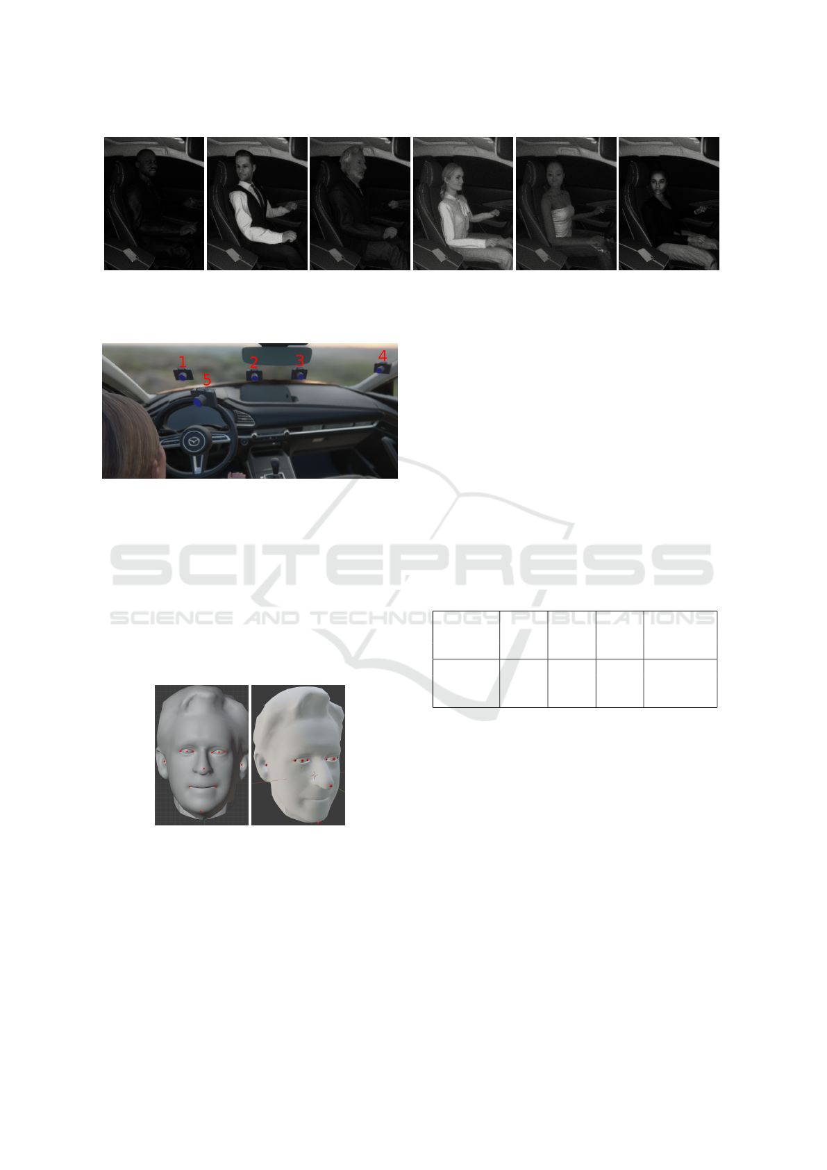
(a) Man 1. (b) Man 2. (c) Man 3. (d) Woman 1. (e) Woman 2. (f) Woman 3.
Figure 5: Rendering of the six different 3D models we use for data generation of our synthetic data generation pipeline. With
these models we try to cover a broad range of different appearances of humans and their facial land marks.
Figure 6: Visualization of all the camera positions of all the
synthetic experiments. Camera 1 represents the first camera
used for all experiment setups. For the second camera, the
specific location changes: Camera 2 is used for the camera
pose with label Side, camera 3 for Far Side, camera 4 for
Regular, and camera 5 for Near in Table 2.
most 5cm from each other, the mean Euler differ an-
gles 1.3 degrees at most. The standard deviations of
the selected accuracy metrics are in the same orders of
magnitude. Thus, our experiments indicate no signif-
icant decrease of accuracy for various camera poses
relative to the head pose.
Figure 7: Correspondence between 2D facial landmarks and
the 3D head model. Left: 2D facial landmarks on 3D head.
Right: 3D head model fitted according to facial landmarks.
4.6 Impact of Different Head Models
To examine the impact of different head models, we
created a dataset with a different head model. As
our data is synthetically generated, we have access to
the true 3D head model. Figure 7 shows the 2D fa-
cial landmarks (left) and the corresponding 3D head
model (right). Table 2 sequence Id 9 contains the eval-
uation results with the true 3D head model. Sequence
Id 2 shows the results using a generic 3D head model.
The difference of the mean distance is 0.1 cm, and the
difference of the mean Euler angle is 3 degrees for the
generic head model and the exact head model.
Both differences are not significant enough to state
that the exact head model performs better (or worse)
compared to the generic head model. It is remarkable
that against our intuition, the default head model does
not perform better than the exact 3D head model. We
reason this might be due to inaccuracies in the anno-
tation of the facial landmark keypoints in the dataset
we chose to train our deep learning network on.
Table 4: Performance using real data captured by using the
Opti-Track Motive camera setup.
Calib. Mean Mean Std. Mean Std.
Object Dist. Euler Dist. Euler
[m] [deg] [m] [deg]
Checker- 0.017 0.3 0.007 0.0
board
Person 0.174 4.8 0.056 3.1
4.7 Real Data
In order to verify that our approach generalizes to real
data, we performed experiments with data captured
by the Opti-Track Motive camera system (Natural-
Point Inc., 2021). We created a setup as similar as
possible to the experiment we describe in Section 4.3.
A person’s head is rotating from the front camera to
the side camera, which is approximately 90 degrees
to the left side of the person. We additionally perform
camera pose estimation using a checkerboard, giving
us a baseline for the performance of the head pose
based camera pose estimation algorithm.
As can be seen in Table 4, the mean distance of the
head pose based camera calibration differs on average
by 17.4cm and the Euler rotation on average by 4.83
degrees. These values show that our approach gener-
Camera Pose Estimation using Human Head Pose Estimation
883
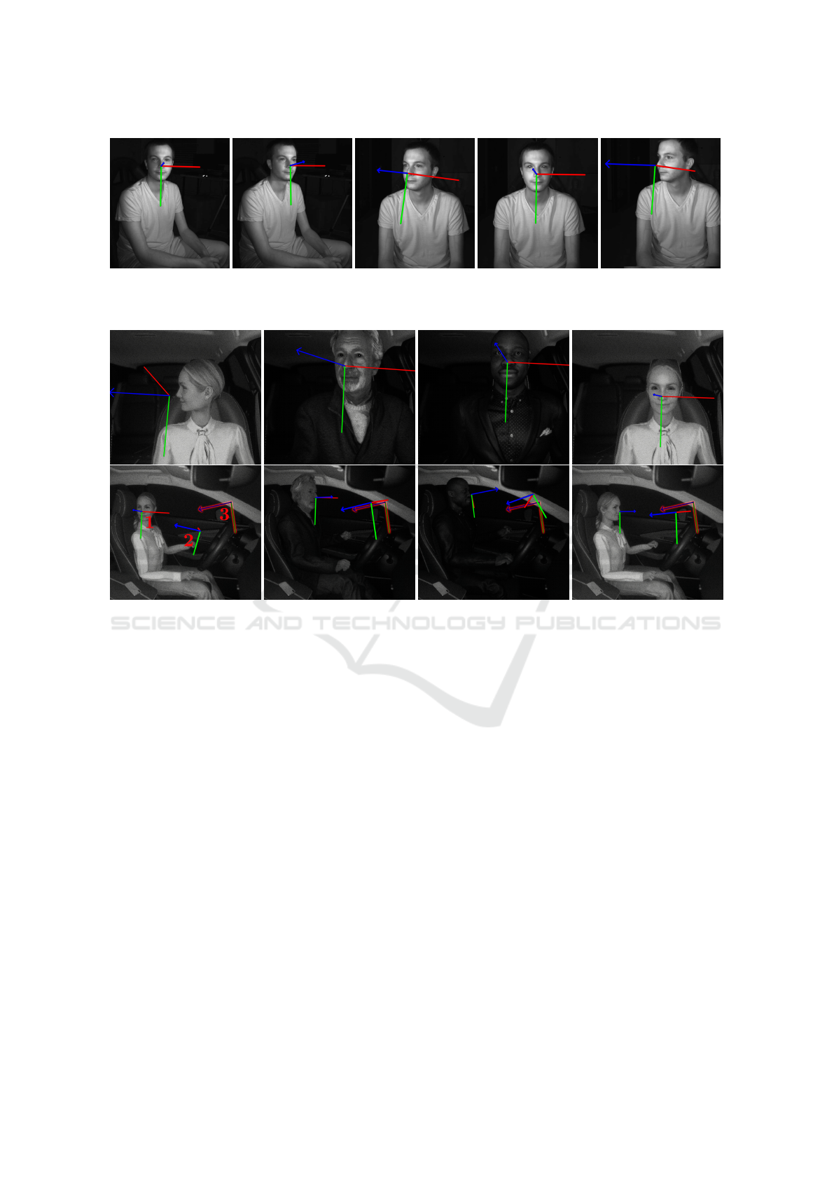
Figure 8: Head pose estimation results from real camera input. As can be seen in the qualitative results on synthetic input
data (see Figure 9), the head pose estimation is significantly more stable and accurate on real data than on synthetic data. This
result is expected as the 2D facial landmark detector has been trained on real input data.
(a) Distance: 0.285m
Mean Euler: 14.8°.
(b) Distance: 0.130m
Mean Euler: 22.1°.
(c) Distance: 0.163m
Mean Euler: 8.9°.
(d) Distance: 0.137m
Mean Euler: 10.2°.
Figure 9: Qualitative results of the synthetic dataset. The 3D-axis (1) represents the estimated head pose. The 3D axis (2)
represents the estimated camera pose and the 3D-axis with the red outline (3) represents the ground truth camera pose. The
first row represents the forward-facing camera and the second row shows the side-facing camera. A nearby-positioned and
similarly-rotated 3D axis (2) of the estimated camera pose relative to the 3D axis (3) of the ground truth camera pose indicates
a more accurate camera pose estimation.
alizes to the real world. Interestingly, the mean Eu-
ler and distance metric is considerably lower for the
real data than the synthetic data. This phenomenon is
most likely due to the fact that the deep learning based
facial landmark extractor is better at extracting the fa-
cial landmarks of real human faces, rather than syn-
thetically rendered human faces. Qualitatively, it can
be seen in Figure 8 that the head pose estimation al-
gorithm provides more stable head rotation estimates
for real data than for the synthetic data.
4.8 Qualitative Evaluation
In this subsection, we evaluate the results of the head
pose based camera pose estimation qualitatively. We
compare the ground truth with the results of our cam-
era pose estimation result in Figure 9. It can be seen
that the main driving factor for a reliable head pose
based camera pose estimation is a proper head pose
estimation. For cases in which the head pose is es-
timated more precisely, the resulting camera pose is
also estimated more accurately. Comparing the syn-
thetic head pose estimation in Figure 9 with head pose
estimations on real data in Figure 8 reveals why the
mean Euler difference and mean distance for the real
dataset are lower. The head pose estimation for the
real image captures is qualitatively superior compared
to the synthetic dataset. There are no unexpected rota-
tions present and the nose is always the origin of the
estimated head coordinate system. Our results indi-
cate that our head pose based camera pose estimation
generalizes to real-world applications. Thus, our ap-
proach will likely perform satisfactory in a real world
application as well.
VISAPP 2022 - 17th International Conference on Computer Vision Theory and Applications
884

5 CONCLUSION AND FUTURE
WORK
We have demonstrated the feasibility of a novel
single- and multi-camera pose estimation technique
which relies exclusively on the computed 3D head
pose of a human in the scene. A broad range of ex-
periments were carried out on simulated and real im-
ages of vehicle cockpit scenes with varying camera
configurations. Our tests on real multi-camera data
have shown an average translational and rotational er-
ror of about 17 cm and less than 5 degrees, respec-
tively. The proposed method can be applied to use
cases where a certain decrease in accuracy compared
to traditional checkerboard calibration is outweighed
by the natural, easy and flexible handling of the head
pose based calibration. Such use cases include camera
setups within the cockpit of a vehicle, train or plane,
where one or more cameras focus on the occupants,
for example, for the purpose of attention monitoring
or early sensor fusion in a multi-camera environment.
Other potential applications include robot attention
tracking or monitoring costumer interest in automated
stores.
In future work, the 2D facial landmarks employed
in our approach and symmetries typically present in
human faces could potentially be used to extend our
approach to estimate the camera intrinsics as well.
This would allow for the extraction of a full camera
calibration from human faces as a calibration object.
Currently, our approach relies on detecting 2D facial
landmarks for head pose calculation. Further research
could try to alleviate the requirements of facial land-
marks detection in order to generalize the head pose
estimation algorithm to viewing conditions where the
human face is not visible to all cameras.
ACKNOWLEDGEMENTS
This work was partly supported by the Synthetic-
Cabin project (no. 884336), which is funded through
the Austrian Research Promotion Agency (FFG) on
behalf of the Austrian Ministry of Climate Action
(BMK) via its Mobility of the Future funding pro-
gram.
REFERENCES
Abad, F., Camahort, E., and Viv
´
o, R. (2004). Camera
calibration using two concentric circles. In Proc. of
ICIAR, pages 688–696. 1, 2
Ansar, A. and Daniilidis, K. (2002). Linear pose estimation
from points or lines. In Proc. of ECCV, pages 282–
296. 2
Balasubramanian, V., Nallure, Ye, J., and Panchanathan, S.
(2007). Biased manifold embedding: A framework for
person-independent head pose estimation. In Proc. of
CVPR, pages 1–7. 2
Bleser, G., Wuest, H., and Stricker, D. (2006). Online cam-
era pose estimation in partially known and dynamic
scenes. In Proc. of ISMAR, pages 56–65. 2
Camposeco, F., Cohen, A., Pollefeys, M., and Sattler, T.
(2018). Hybrid camera pose estimation. In Proc. of
CVPR, pages 136–144. 2
Chen, L., Zhang, L., Hu, Y., Li, M., and Zhang, H. (2003).
Head pose estimation using fisher manifold learning.
In Proc. of AMFG, pages 203–207. 2
Fanelli, G., Dantone, M., Gall, J., Fossati, A., and v. Gool,
L. (2013). Random forests for real time 3d face anal-
ysis. IJCV, 101(3):437–458. 2
Fanelli, G., Gall, J., and v. Gool, L. (2011). Real time head
pose estimation with random regression forests. In
Proc. of CVPR, pages 617–624. 2
Gross, R. (2021). How the Amazon Go Store’s AI Works.
Towards Data Science (https://bit.ly/3tVHXi2). 1
Gua, J., Deboeverie, F., Slembrouck, M., v. Haerenborgh,
D., v. Cauwelaert, D., Veelaert, P., and Philips, W.
(2015). Extrinsic calibration of camera networks us-
ing a sphere. Sensors, 15(8):18985–19005. 1
H
¨
odlmoser, M., Micusik, B., and Kampel, M. (2011).
Camera auto-calibration using pedestrians and zebra-
crossings. In Proc. of ICCVW, pages 1697–1704. 2
Huang, C., Ding, X., and Fang, C. (2010). Head pose esti-
mation based on random forests for multiclass classi-
fication. In Proc. of ICPR, pages 934–937. 2
Kosuke, T., Dan, M., Mariko, I., and Hideaki, K. (2018).
Human pose as calibration pattern: 3d human pose
estimation with multiple unsynchronized and uncal-
ibrated cameras. In Proc. of CVPRW, pages 1856–
18567. 2
Lamia, A. and Moshiul, H. M. (2019). Vision-based driver’s
attention monitoring system for smart vehicles. In In-
telligent Computing & Optimization, pages 196–209.
1
Li, Y., Wang, S., and Ding, X. (2010). Person-independent
head pose estimation based on random forest regres-
sion. In Proc. of ICIP, pages 1521–1524. 2
Liu, X., Liang, W., Wang, Y., Li, S., and Pei, M. (2016). 3d
head pose estimation with convolutional neural net-
work trained on synthetic images. In Proc. of ICIP,
pages 1289–1293. 2
Lu, C.-P., Hager, G., and Mjolsness, E. (2000). Fast and
globally convergent pose estimation from video im-
ages. TPAMI, 22(6):610–622. 3
Manolis, L. and Xenophon, Z. (2013). Model-based pose
estimation for rigid objects. In Computer Vision Sys-
tems, pages 83–92. 2
Moliner, O., Huang, S., and
˚
Astr
¨
om, K. (2020). Better
prior knowledge improves human-pose-based extrin-
sic camera calibration. In Proc. of ICPR, pages 4758–
4765. 2
Camera Pose Estimation using Human Head Pose Estimation
885

NaturalPoint Inc. (2021). Optitrack motive camera sys-
tem. https://optitrack.com/software/motive/. Ac-
cessed: 2021-07-26. 4, 7
N
¨
oll, T., Pagani, A., and Stricker, D. (2010). Markerless
camera pose estimation - an overview. In Proc. of
VLUDS, volume 19, pages 45–54. 2
Pajdla, T. and Hlav
´
ac, V. (1998). Camera calibration and
euclidean reconstruction from known observer trans-
lations. In Proc. of CVPR, pages 421–426. 1
Patacchiola, M. and Cangelosi, A. (2017). Head pose es-
timation in the wild using convolutional neural net-
works and adaptive gradient methods. Pattern Recog-
nition, 71:132–143. 2
Puwein, J., Ballan, L., Ziegler, R., and Pollefeys, M. (2014).
Joint camera pose estimation and 3d human pose es-
timation in a multi-camera setup. In Proc. of ACCV,
pages 473–487. 2
Raytchev, B., Yoda., I., and Sakaue, K. (2004). Head pose
estimation by nonlinear manifold learning. In Proc. of
ICPR, volume 4, pages 462–466. 2
Rodrigues, R., Barreto, J., and Nunes, U. (2010). Camera
pose estimation using images of planar mirror reflec-
tions. In Proc. of ECCV, pages 382–395. 2
Ruiz, N., Chong, E., and Rehg, J. (2018). Fine-grained
head pose estimation without keypoints. In Proc. of
CVPRW. 2
Shao, X., Qiang, Z., Lin, H., Dong, Y., and
Wang, X. (2020). A survey of head
pose estimation methods. In Proc. of
iThings,GreenCom,CPSCom,SmartData,Cybermatics,
pages 787–796. 2
Stiefelhagen, R., Yang, J., and Waibel, A. (2001). Track-
ing focus of attention for human-robot communica-
tion. Citeseer. 1
T.-Y. Lin, M. M., Belongie, S., Bourdev, L., Girshick, R.,
Hays, J., Perona, P., Ramanan, D., Zitnick, C. L., and
Doll
´
ar, P. (2014). Microsoft coco: Common objects in
context. In Proc. of ECCV, pages 740–755. 3
Valle, R., Buenaposada, J., Vald
´
es, A., and Baumela, L.
(2016). Head-pose estimation in-the-wild using a ran-
dom forest. In Proc. of AMDO, pages 24–33. 2
Venturelli, M., Borghi, G., Vezzani, R., and Cucchiara, R.
(2016). Deep head pose estimation from depth data
for in-car automotive applications. In Proc. of ICPRW,
pages 74–85. 2
Wei, S., Ramakrishna, V., Kanade, T., and Sheikh, Y.
(2016). Convolutional pose machines. In Proc. of
CVPR, pages 4724–4732. 3
Wu, H., Zhang, K., and Tian, G. (2018). Simultane-
ous face detection and pose estimation using con-
volutional neural network cascade. IEEE Access,
6:49563–49575. 2
Xu, Y., Li, Y.-J., Weng, X., and Kitani, K. (2021). Wide-
baseline multi-camera calibration using person re-
identification. In Proc. of CVPR, pages 13134–13143.
1
z. Qiao, T. and Dai, S. (2013). Fast head pose estimation
using depth data. In Proc. of CISP, pages 664–669. 2
Zhang, Z. (1999). Flexible camera calibration by viewing a
plane from unknown orientations. In Proc. of ICCV,
volume 1, pages 666–673. 1
Zhang, Z. (2000). A flexible new technique for camera cal-
ibration. TPAMI, 22(11):1330–1334. 1
VISAPP 2022 - 17th International Conference on Computer Vision Theory and Applications
886
