
Design and Locomotion Control of a Myliobatid-inspired Robot
Actuated by Passively-flexing Pectoral Fins
Songzi Guo
1
, Zhiyin Li
1
and Jinhua Zhang
2
1
China Ship Design and Development Center, Wu’han 430034, China
2
Key Laboratory of Education, Ministry for Modern Design and Rotor-Bearing System, Xi’an Jiaotong University,
Xi’an 710049, China
Keywords: Bionic Design, Robot Fish, Flexible Pectoral Fin, Bio-Inspire.
Abstract: This article proposes the mechanical design of a myliobatid-inspired robot (XJRoman-Ⅰ) based on oscillatory
swimming mechanism for both stability and agile manoeuvrability. Inspired by anatomical studies, a pair of
passively bending pectoral fins are developed to generate propulsive force for the prototype. An elevator is
adopted to adjust its pitch attitude. Primary experimental research on the effect of fin’s spanwise stiffness on
swimming performance is performed to improve its swimming performance. By embedding a stiff rod into
the fin’s leading edge, the thrust and lateral force generated by the fins are improved significantly. Finally, a
CPG-based control method is introduced to make the prototype achieve different locomotion patterns
including cruising by flapping pectoral fins and turning by modulating phase relation of pectoral fins. This
paper mainly focuses on propulsive capability of stability and agility for the prototype, and expects to propose
an excellent underwater vehicle covering wide range of applications.
1 INTRODUCTION
Traditional underwater vehicles play an important
role in underwater explorations. But with the growing
demands for pelagic and deep-sea missions, they
couldn’t well adapt to these complex and
challengeable operating scenarios because of
limitation of their propulsive mechanisms. Hence, in
order to solve this conundrum, biologists and
engineers attempt to mimic propulsive mechanisms
of marine animals to enhance the performance of
underwater vehicles. Admittedly, marine animals are
quite different from underwater vehicles in many
aspects. Yet even so, by understanding how aquatic
animals achieve these inborn advantages, engineers
can be inspired to develop a variety of novel undersea
robots like a robotic dolphin (Yu, 2017), knife-fish
(Liu, 2017) and trout (Takemura, 2011) giving man’s
horizon further into the ocean than ever before.
Among the numerous aquatic animals, myliobatid,
renowned as a large open-water swimmer, has
streamlined body shape and peculiar propulsive
mechanism (Rosenberger, 2001). While the majority
of fishes use their caudal fin to generate propulsion
and pectoral fins to keep balance, rays synchronically
or asynchronously flap their flexible pectoral fins on
each side of the body to achieve agile manoeuvre and
stable locomotion, which take great advantages over
other caudal fin-based fishes in long-distance
swimming (Breder,1926) and agile motion
(Fish,2018).
Researchers intensively investigated kinematics
characteristics of myliobatid fishes, attempting to
reveal the mechanism behind such great
comprehensive abilities of high efficiency and
stability during cruise. By analysing the typical
frames of a cruising manta ray, Liu et al (Liu, 2015)
established a kinematics model to delineate
deformation of pectoral fins in both span and chord.
The model indicated that the deformation in the span
becomes significantly at distal part of pectoral fins.
The flexible deformation in span was proved to allow
mantas to perform small radius turns with its ratio as
high as 67 deg/s (Fish et al., 2018), despite their rigid
body (Parson, 2011). Based on the kinematics
research on mantas, various computational
hydrodynamic simulations (Fish et al., 2016) were
carried out and indicated that the flexible distal part
of pectoral fins plays an essential role in mantas’
swimming and generates the majority of thrust. On
top of this, comprehensive experimental studies were
carried out by Clark and Smits (Clark et al, 2006).
Guo, S., Li, Z. and Zhang, J.
Design and Locomotion Control of a Myliobatid-inspired Robot Actuated by Passively-flexing Pectoral Fins.
DOI: 10.5220/0010857000003271
In Proceedings of the 19th International Conference on Informatics in Control, Automation and Robotics (ICINCO 2022), pages 353-360
ISBN: 978-989-758-585-2; ISSN: 2184-2809
Copyright
c
2022 by SCITEPRESS – Science and Technology Publications, Lda. All rights reserved
353
They found the efficiency of a flapping foil is
promoted by flexibility distributed on the foil. With
the help of DPIV technology, Dewey et al (Dewey et
al., 2012; 2013) observed wake topology formed by a
bionic pectoral fin and proposed a resonance theory,
which indicated a maximal efficiency is always
achieved while flapping pectoral fins is actuated
under its resonance frequencies.
By mimicking the kinematics features of
oscillatory batoid fishes, many newly-designed
underwater robots have been developed. In 2011, a
ray-like robot fish was initially design and fabricated
by Low et al (Low, 2012), whose pectoral fin in one
side was actuated by three servos in parallel.
Similarly, this parallel connected actuating system
was also utilized by an improved ray-like robot (Cao,
2019). A cpg-fuzzy-based control method was
introduced to better mimic the swimming gaits of
myliobatid. However, the robot fish can actively
control multiple degrees of freedom along the chord
by means of groups of servos, redundant actuators
lead to extra loss of mechanical energy and limit
swimming performance of robots. Therefore, Chew et
al (Chew, 2016) have developed a manta-like robot
merely actuated by two servos. Because of the
lightweight and compact design, maximal swimming
speed of this robot fish can reach to 1.7 body length
per second.
In this paper, the design of a myliobatid-inspired
robot equipped with a pair of passively bending
pectoral fins based on oscillatory swimming
mechanism is proposed. The fin’s design is based on
the anatomical structure of an eagle-ray. A traveling
wave alone the chord, coupling with a vertical wave
alone the wingspan is presented on the flexible fin
during flapping in the water. In addition, an
experiment on the effect of span-wise stiffness is
carried out to improve the swimming performance of
the prototype. Finally, the prototype equipped with
the optimized pectoral fins is tested in a pool to verify
its capability of locomotion.
2 FROM BIOMIMETIC SUBJECT
TO BIOINSPIRED ROBOT
2.1 Overview of the Prototype
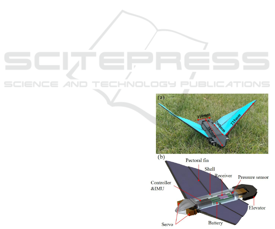
To mimic stable and flexible swimming mode of
myliobatid, a bionic oscillatory robot equipped with a
pair of flexible pectoral fins is constructed, as shown
in Figure1(a). The robot prototype has a flat and
streamlined body shape suitable to achieve both fast
and stable motions in the water and equip with a pair
of flexible pectoral fins, and can be divided into four
parts: (1) a head cabinet fixing two of actuating servos
(Omg, 40kgf.cm) providing torque force for the
bionic fins; (2) a central waterproof shell containing
electric components; (3) an elevator to adjust pitch
attitude; (4) a pair of flexible pectoral fins providing
propulsive force for the prototype. The head cabinet
as well as the central shell are made of the lightweight
material (nylon-12), whose density is close to water.
The weight of the robot is 680g, and it can provide an
extra load capacity of 200g. A central controller
(RoboMaster, DJI) powered by FreeRTOS system is
adopted to control locomotion of the prototype.
Considering that the effect of attenuation for signals
will be intensive with the increasing frequency in the
water, a radio module with lower transmission
frequency is adopted as communication unit.
Additionally, the central waterproof shell
accommodates sensors for underwater environment
perception. An inertial measurement unit (IMU)
embedded in the controller is arranged in parallel with
the robot principle axis to sense the three-dimensional
attitude for the prototype with a sampling rate of 50
Hz. A developed pressure sensor MS5837 is mounted
at the end of the shell to gauge hydraulic pressure
corresponding to the depth where the robot stays. It
has a 0.2mbar resolution in a scale range of 0-30bar.
The elevator at the stern of the prototype driven by a
servo performs vertical rotation to provide pitch
torque for the prototype.
Figure 1: (a) Isometric view of the robotic prototype. (b)
Components of the robot prototype.
ICINCO 2022 - 19th International Conference on Informatics in Control, Automation and Robotics
354

Table 1: Main Technical Specifications of the Robotic
Prototype.
Items Characteristics
Dimension
385mm
×560mm×50mm
Total mass 680g
Control unit STM32F407IGH
Sensors IMU(BMI088), Pressure sensor
Drive units
Servo
×3(waterproof)
Communication unit AS32170-170MHz
Power supply 11.1V(2200mAh-Li)
2.2 Design and Fabrication of Bionic
Pectoral Fins
The design of the bionic pectoral fin is based on the
anatomical details of a myliobatid swimmer, eagle-
ray. It is a typical swimmer using oscillatory model
embodying an excellent balance between
manoeuvrability and efficiency. For this reason, their
anatomical characteristics would inspire the design of
next-generation underwater vehicles. To uncover the
outstanding swimming performance of eagle-rays, we
conduced anatomical experiments on its pectoral fins
to discover the smallest detail in musculoskeletal
structure, which is shown in Figure2.
Figure 2: (a) The fin’s skeletal structure of an eagle-ray.
(b) The cross-section of the dissected pectoral fin.
The pectoral fin of the eagle-ray is approximately
200 mm in chord and 220 mm in span, where span is
measured from the fin tip to the root. The fin’s aspect-
ratio is close to 2.2 that is the ratio of the span-wise
length to the fin’s surficial area.
After removing tissues from the specimen, skeletal
structure can be clearly observed in Figure2(a). The
pectoral fin consists of an array of 175 fin-rays. Each
of the fin-ray is composed by several segments
connected by cartilaginous joints. These segments
extend out from the root to the edge of the pectoral fin
and arrange in radial formation. In Figure2(b), the
thickness of the pectoral fin decreases from the basal
part to the distal part. This kind of skeletal and
muscular structure is considered to be favourable for
the range of motion for fins tip, by which agility and
efficiency of eagle-rays can be enhanced.
Additionally, skeletal connections also exist between
the adjacent radial segments. This connective tissue
is termed cross-bracing, which can limit the
oscillatory amplitude of adjacent fin-rays and
increase the chord-wise stiffness in the pectoral fin
necessary for the transmission of traveling wave
along the chord-wise direction.
Based on the morphologic characteristics and
anatomical details of the specimen, the design of a
bionic pectoral fin to mimic the oscillatory propulsion
mechanism is proposed. The chord-length and span-
length of the bionic fin are 220mm and 200mm,
respectively. The AR of the bionic fin is about 2.2.
The leading edge that has the longest length
among fin-rays connects with a servo (Omg,
40kgf.cm), providing oscillatory force for the
pectoral fin. The rest of the fin-rays at the middle and
the end of the bionic pectoral fin respectively can
passively control the wavelength alone the chord
presenting on the pectoral fin. To make the bionic
pectoral fin achieve passive deformation alone the
wingspan and allow the flexible membranes to
maintain it shape while flapping in the water, all of
the fin-rays are made of nylon with high-ductility.
The thickness of the fin-rays decreases from the basal
part to the distal part. Therefore, the tip of the pectoral
fin can achieve more significant deformation than
proximal part. Two of the flexible membranes are
made of silicon rubber and attached to the fin-rays by
adhesive (E41, Wacker). Since M4601, a kind of two-
component silicone rubber, has appropriate tensile
strength (6.5N/mm
2
) and lower hardness (28A)
compared with other silicon rubbers, it is adopted to
fabricate flexible membranes for the bionic pectoral
fins. Firstly, the unmixed M4601-A and M4601-B are
poured into a container by weight of 1:9. After
degassing in a vacuum chamber, the mixed material
is poured into resin moulds where the demould
releaser has been sprayed. And then, after curing at
room temperature for 12 hours, the vulcanized
specimen is stripped from the moulds. The cured fin-
like membranes have 2mm in thickness. Finally,
Design and Locomotion Control of a Myliobatid-inspired Robot Actuated by Passively-flexing Pectoral Fins
355

when all of the compliant membranes are fabricated.
They are adhered to the compliant fin-rays. The
fabricated bionic pectoral fin is shown in Figure3.
Figure 3: The fabricated bionic pectoral fin, noted that in
this paper the bionic fins are dyed into different colours by
fluorescent agent to make them more distinguishable.
2.3 Experiment on Bionic Pectoral Fins
In order to improve propulsive performance for the
robot, experimental research was carried out to
investigate the effect of stiffness distribution along
the leading edge on thrust and lateral force generated
by the pectoral fins. On top of that, the position of the
passive bending along the leading edge is investigated,
since it determines the proportion of the distal part on
the bionic fin, which has been proved to be closely
relative to thrust generation in Fish’s work (Fish,
2016).
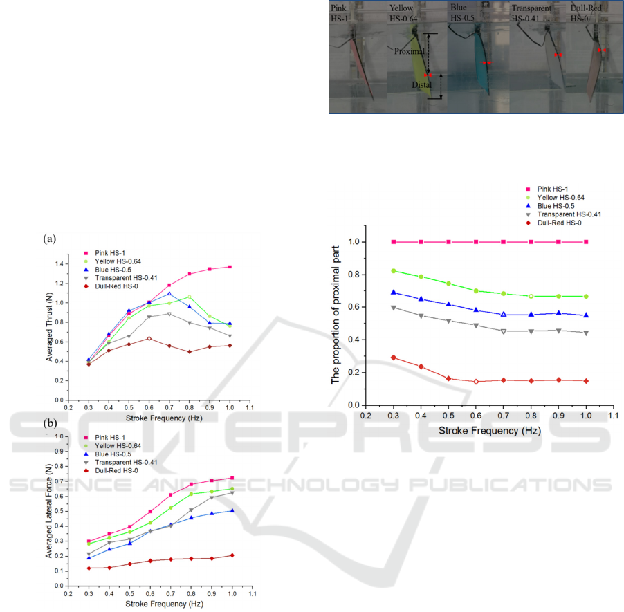
In the experiment, we studied five bionic fin’s
configurations whose leading edge is different in the
proportion of high stiffness part marked with a red
bracket in Figure4(a). An aluminium rod is embedded
into the rear side of fin’s leading edge to form discrete
region with high stiffness along the span-wise
direction. The fabricated bionic fins are demonstrated
in Figure4(b) where the proportion of the high
stiffness part decreases from 1 ( the pink pectoral fin)
to 0 (dull-red pectoral fin). In the fins’ naming
scheme, ‘HS-*’ refers to the proportion of the leading
edge with high stiffness part.S
Figure 4: (a) The leading edges embedded with different
length of aluminium rods. (b) The five fabricated bionic fins
with different scale of high stiffness region.
The experimental apparatus is shown in Figure5.
A servo clamped by a carriage was used to actuate the
bionic fins. The flapping apparatus is mounted on the
interface of a 6-axis force torque sensor (ATI-Mini40,
0~20N) and submerged in a water tank. Since the
passive bending appearing on the leading edge is
critical to the thrust generation, a high-speed camera
(Phantom, v1612) was placed in the front of the water
tank to capture the frames to investigate the passive
bending appearing on the leading edge during
flapping.
Figure 5: Annotated diagram of the experimental apparatus.
Myliobatid prefers to change the flapping
frequency to meet different motion requirements
(Fish, 2016). Therefore, the five bionic fins were
actuated under different stroke frequencies from 0.3
to 1.0 Hz with a constant flapping amplitude of 80°.
To make the experimental data acquired in our work
reliable, the collecting duration of each set of data
were lasting for 20 flapping circles. The thrust and
lateral force throughout ten stable flapping circles
were selected to obtain the averaged thrust and lateral
force.
Cycle-averaged thrust and lateral force generated
by the bionic fins are shown in Figure6(a) and
Figure6(b), respectively. Compared with the bionic
fin’s configuration HS-0 (Dull-red) without stiffener
in the leading edge, the other fin’s configurations
have overall increases in averaged thrust and lateral
force. Additionally, except for the bionic fin termed
HS-1 (Pink), the averaged thrust increases with the
increasing stoke frequency before a turning point,
where the averaged thrust reaches its maximum and
then starts to decrease. On the other hand, the
averaged lateral force demonstrates incremental trend
with the increasing stroke frequency. The fin’s
configuration HS-1 embedded with a stiff rod as long
as its leading edge can achieve the highest cycle-
averaged thrust among the fin’s design, which is
1.32N at stroke frequency of 1.0 Hz. However, its
generated lateral force can’t be ignored. Because a
pair of bionic pectoral fins mounted on the robot
ICINCO 2022 - 19th International Conference on Informatics in Control, Automation and Robotics
356
prototype couldn’t be perfectly symmetrical in size,
the discrepancy in lateral force make the prototype
difficult to keep its course. If the fundamental need
for the robot prototype is to perform cursing
locomotion that focuses on the swimming speed and
stability, the ideal pectoral fins are expected to
provide a significant thrust but relatively unobvious
magnitude of lateral force to maintain the swimming
stability. Based on the experimental result, the HS-0.5
(blue) is chosen as an ideal actuator for the robot
prototype, as it can achieve great averaged forces
even closer to that of the HS-1 at stroke frequencies
from 0.3 Hz to 0.7Hz while the averaged lateral forces
are relatively lower than other pectoral fins.
Figure 6: (a) The cycle-averaged thrust and (b) the lateral
force at different stroke frequencies from 0.3 Hz to 1.0 Hz.
The hollow symbol demonstrates the stroke frequency
climbs to the turning point, where the averaged thrust
begins to drop down for the next stroke frequency.
While a bionic fin is flapping, the position of a
passively-bending point along the fin’s leading edge
marked with a couple of red arrows in Figure7 can
serve as an indicator for the magnitude of
hydrodynamic load on the bionic fin, which is relative
to the force generation of the bionic fin. Therefore,
the image data acquired from the high-speed camera
were analysed to obtain the position of the passively-
bending points.
Figure 7: The snapshots of the different designs of bionic
fins while actuating at stroke frequency of 1 Hz. The
passively-bending points are mark with red arrows.
Figure 8: The proximal stiff part occurring on the bionic fin.
The hollow symbol demonstrates the stroke frequency
where the variation tendency in the chart is changed.
The proportion of the proximal stiff part occurring
on the bionic fin is shown in Figure8. For the fin’s
configuration of HS-1.0 (Pink), the passive bending
didn’t appear on its leading edge, as the leading edge
of the fin is rigid enough to resist the reactive force.
In contrast, the proximal stiff part of the other bionic
fins decreases with the stroke frequency increasing
because of the increasing hydrodynamic load on the
fin. However, as the stroke frequency further
increases to a restraint frequency, the proportion of
the proximal part begins to keep a constant value. It
is because the embedded aluminium rod commences
to restrain the passively-bending point from shifting
towards proximal part further,
It should be noted that compared with Figure6(a)
and Figure8, the bionic fins reach their maximum in
averaged thrust as the proportion of the proximal part
just drop down to its bottom. For the next stroke
frequency, the generated thrust begins to decrease.
We deduce that the distal part on the bionic fin ploys
an important role in thrust generation. While the
stroke frequency increases from 0.3 Hz to the trans-
Design and Locomotion Control of a Myliobatid-inspired Robot Actuated by Passively-flexing Pectoral Fins
357
frequency, the increment in thrust takes advantage
over the increment in drag force. Hence, the gross
magnitude of the thrust shows a growing trend. On
the contrary, while stroke frequency increases beyond
the trans-frequency, the increment in drag force takes
advantage over the increment in thrust, since the scale
that can generate thrust is restrained.
3 LOCOMOTION CONTROL
BASED ON A CPG-BASED
CONTROL METHOD
Owing to central pattern generators (CPGs)
modulating the rhythmic movements, animals can
perform various locomotion patterns with excellent
stability. They can be also employed to control
coordination locomotion of robots with multi-degree
of freedom especially in performing swimming
patterns of robotic fish and other types of robots
(Zhou and Low, 2012). Many sorts of the CPG
models have been employed to control locomotion for
bio-inspired robots, such as Hopf model (Zhou and
Low, 2010a), Matsuoka’s model (Matsuoka, 1985)
and Ijspeert’s model (Ijspeert et al., 2007). In this
paper, we adopt a simplified linear CPG model
proposed by (Wang et al., 2017) to generate rhythmic
signals for three servomotors corresponding to the
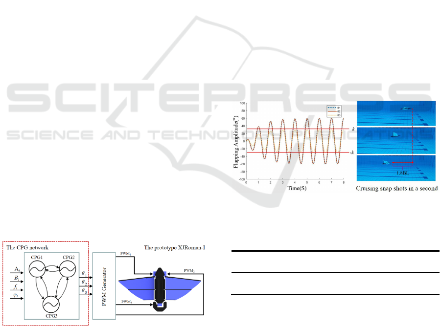
fins and the tail. The CPG controller shown in Figure
9 is composed of three coupled oscillators and it is
implemented as follows:
(-)
(-)
2(--)
cos( )
i
iiii
iiii
i i ij j i ij
jT
iii i
aAa
bBb
xf xx
ba x
η
β
π
μϕ
θ
∈
=
=
=+
=+
(1)
Figure 9: The CPG network of XJRoman-Ⅰ.
The parameters a
i
, b
i
and x
i
are state variables of the
CPG model and represent the amplitude, offset and
phase of the rhythmic signal produced by the ith
oscillator. A
i
, B
i
and f
i
are control parameters to
modulate the desired flapping amplitude, offset and
frequency. φ
ij
is a parameter for the desired phase
relation between the ith oscillator and jth oscillator.
μ
ij
is a coefficient denoting the coupling strength
between the ith oscillator and jth oscillator. η
i
and β
i
are converging coefficient affecting the convergence
speed of the CPG network. The output θ
i
is the input
angle of the servomotor. The subscripts i=1, 2, 3
correspond to the left pectoral fin, right pectoral fin
and the tail of the prototype, respectively
4 SWIMMING TEST FOR THE
PROTOTYPE
In order to acquire cruise speed of the prototype, we
tested the prototype equipped with the blue pectoral
fins (HS-0.5) in a swimming pool under stroke
frequencies from 0.5 Hz to 1.2 Hz with a fixed
flapping amplitude (80°). In cruise pattern (Figure10),
CPG1 and CPG2 modulate synchronous rhythm
signals to actuate pectoral fins to keep the robot
swimming along the straight course. While actuated
at the a stroke frequency of 0.8 Hz, the prototype can
reach its maximal cruising speed at 1.8 BL/s (body
length per second).
Figure 10: Output signals of the CPGs while the prototype
performing cruise locomotion.
Table 2: Parameter Values in CPGs (Cruise Pattern).
f
i
φ
ij
A
i
B
i
α
i
β
i
μ
ij
[1,1,1] 0 [60,60,k] [0,0,0] [1,1,1] [1,1,1] 1
In turning pattern, The modulated signals are
recorded in Figure11, where the CPG1 and CPG2
modulate asynchronous rhythm signals to actuate the
pectoral fins asynchronously to alter swimming
course of the robot gradually. Based on the snap shots
of the turning pattern, the CPG-based controller can
make the prototype alter swimming gaits stably.
ICINCO 2022 - 19th International Conference on Informatics in Control, Automation and Robotics
358
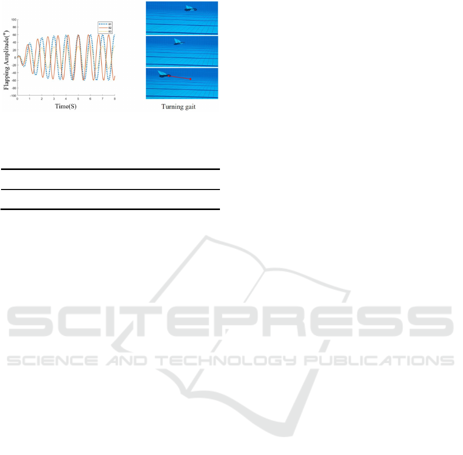
Figure 11: Output signals of the CPGs while the prototype
performs turning gait.
Table 3: Parameter Values in CPGs (TurningPattern).
f
i
φ
ij
A
i
B
i
α
i
β
i
μ
ij
[1,1.2,1]
0
[60,60,k] [0,0,0] [1,1,1] [1,1,1]
1
5 POTENTIAL ONGOING WORK
In further work, we are going to investigate
propulsive efficiency of the robot prototype, since it
is a critical parameter to evaluate the swimming
performance of the prototype, especially in fulfilling
long-distance mission.
On the other hand, since the flapping bionic fin
can also provide lift force for the robot, it can be used
to achieve gliding locomotion for the prototype to
save energy during swimming. In our further work,
we also plan to investigate the gliding locomotion for
the prototype to make it fulfil a long-distance travel.
6 CONCLUSION
In this study, a prototype of oscillatory robot based on
the combination of biological swimming mechanisms
and morphological features was proposed to make the
prototype achieve both fast and stable locomotion
through a pair of bionic pectoral fins. Moreover,
primary research on the effect of fin’s span-wise
stiffness on the propulsion performance was carried
out. The experiment investigated the thrust and lateral
force generation of five fin designs embedded with
different length of aluminum rods. The experimental
result shows that embedding a stiff rod into the fin’s
leading edge can cause the thrust and lateral force to
improve significantly at stroke frequency beyond
0.5Hz; up to 138% increasement in thrust for the HS-
1 (pink) relative to HS-0. In addition, the result also
suggests that the bionic fin named HS-0.5 (blue) takes
advantage over other designs in capacity of achieving
stable and fast motion for the prototype.
The fast motion performed by the prototype
shows the passively-flexing pectoral fin proposed in
our research is an excellent candidate for underwater
propulsive mechanism.
ACKNOWLEDGEMENTS
This research was financially supported by the
National Nature Science Foundation of China (No.
91748123).
REFERENCES
Yu, J., Liu, J., Wu, Z., & Fang, H.. (2017). Depth control of
a bioinspired robotic dolphin based on sliding mode
fuzzy control method. IEEE Transactions on Industrial
Electronics, 1-1.
Liu, H., Taylor, B., & Curet, O. M.. (2017). Fin ray stiffness
and fin morphology control ribbon-fin-based
propulsion. Soft Robot, 103-116.
Rosenberger, L. J.. (2001). Pectoral fin locomotion in
batoid fishes: undulation versus oscillation. Journal of
Experimental Biology, 204(Pt 2), 379-394.
Takemura, R., Akiyama, Y., Hoshino, T., & Morishima, K..
(2011). Chemical switching of jellyfish-shaped micro
robot consisting only of cardiomyocyte gel. Solid-state
Sensors, Actuators & Microsystems Conference. IEEE.
Breder, C. M. (1926). The locomotion of fishes.
Zoologica,4.
Fish, F. E., Kolpas, A., Crossett, A., Dudas, M. A., & Bart-
Smith, H.. (2018). Kinematics of swimming of the
manta ray: three-dimensional analysis of open-water
maneuverability. Journal of Experimental Biology,
221(Pt 6), jeb.166041.
Low, K. H., Zhou, C., Seet, G., Bi, S., & Cai, Y.. (2012).
Improvement and testing of a robotic manta ray
(RoMan-III). IEEE International Conference on
Robotics & Biomimetics. IEEE.
Cao, Y., Lu, Y., Cai, Y., Bi, S., & Pan, G.. (2019). Cpg-
fuzzy-based control of a cownose-ray-like fish robot.
Industrial Robot, ahead-of-print(ahead-of-print).
Liu, G., Ren, Y., Zhu, J., Bart-Smith, H., & Dong, H..
(2015). Thrust producing mechanisms in ray-inspired
underwater vehicle propulsion. Theoretical and
Applied Mechanics Letters, 5(001), 54-57.
Fish, F. E., Kolpas, A., Crossett, A., Dudas, M. A., & Bart-
Smith, H.. (2018). Kinematics of swimming of the
manta ray: three-dimensional analysis of open-water
maneuverability. Journal of Experimental Biology,
221(Pt 6), jeb.166041.
Parson, J. M., Fish, F. E., & Nicastro, A. J.. (2011). Turning
performance of batoids: limitations of a rigid body.
Design and Locomotion Control of a Myliobatid-inspired Robot Actuated by Passively-flexing Pectoral Fins
359

Journal of Experimental Marine Biology & Ecology,
402(1-2), 12-18.
Fish, F.E., Schreiber, C.M., Moored, K.W., Liu, G., Dong,
H.and Bart Smith, H. (2016), “Hydrodynamic
performance of aquatic flapping: efficiency of
underwater flight in the manta”, Aerospace, Vol. 3 No.
3, pp. 1-24.
Clark, R. P., & Smits, A. J., (2006). Thrust production and
wake structure of a batoid-inspired oscillating fin.
Journal of Fluid Mechanics, 562(562), 415-429.
Dewey, P. A., Carriou, A., & Smits, A. J., (2012). On the
relationship between efficiency and wake structure of a
batoid-inspired oscillating fin. Journal of Fluid
Mechanics, 691, 245-266.
Dewey, P. A., Boschitsch, B. M., Moored, K. W., Stone, H.
A., & Smits, A. J., (2013). Scaling laws for the thrust
production of flexible pitching panels. JOURNAL OF
FLUID MECHANICS, 732, 29-46.
Chew, C. M., Lim, Q. Y., & Yeo, K. S. (2016).
Development of propulsion mechanism for Robot
Manta Ray. IEEE International Conference on Robotics
& Biomimetics. IEEE.
Wang, W., Gu, D., & Xie, G. (2017). Autonomous
optimization of swimming gait in a fish robot with
multiple onboard sensors. IEEE Transactions on
Systems Man & Cybernetics Systems, 1-13.
Zhou, C.L. and Low, K.H. (2012). Design and locomotion
control of a biomimetic underwater vehicle with fin
propulsion. IEEE/ASME Transactions on
Mechatronics, Vol. 17 No. 1, pp. 25-35.
Zhou, C.L. and Low, K.H. (2010a). Better endurance and
load capacity: an improved design of manta ray robot
(RoManII). Journal of Bionic Engineering, Vol. 7 No.
S4, pp. S137-S144.
Matsuoka, K. (1985). Sustained oscillations generated by
mutually inhibiting neurons with adaptation. Biological
Cybernetics, Vol. 52 No. 6, pp. 367-376.
Ijspeert, A.J., Crespi, A., Ryczko, D. and Cabelguen, J.-M.
(2007). From swimming to walking with a salamander
robot driven by a spinal cord model. Science, Vol. 315
No. 5817, pp. 1416-1420.
ICINCO 2022 - 19th International Conference on Informatics in Control, Automation and Robotics
360
