Calibration of a Telecentric Structured-light Device
for Micrometric 3D Reconstruction
Mara Pistellato
a
, Andrea Albarelli
b
and Filippo Bergamasco
c
DAIS, Universit
`
a Ca’Foscari Venezia, 155, via Torino, Venezia Italy
{mara.pistellato, filippo.bergamasco, albarelli}@unive.it
Keywords:
Camera-projector Calibration, Structured-light Scanning, Telecentric Lenses, Micrometric Surface
Reconstruction.
Abstract:
Structured-light 3D reconstruction techniques are employed in a wide range of applications for industrial
inspection. In particular, some tasks require micrometric precision for the identification of microscopic surface
irregularities. We propose a novel calibration technique for structured-light systems adopting telecentric lenses
for both camera and projector. The device exploits a fixed light pattern (striped-based) to perform accurate
microscopic surface reconstruction and measurements. Our method employs a sphere with a known radius as
calibration target and takes advantage of the orthographic projection model of the telecentric lenses to recover
the bundle of planes originated by the projector. Once the sheaf of parallel planes is properly described in
the camera reference frame, the triangulation of the surface’s object hit by the light stripes is immediate.
Moreover, we tested our technique in a real-world scenario for industrial surface inspection by implementing
a complete pipeline to recover the intersections between the projected planes and the surface. Experimental
analysis shows the robustness of the proposed approach against synthetic and real-world test data.
1 INTRODUCTION
Structured-light approaches adopt a controlled light
source with known geometry to locate the same ma-
terial point from different views, recovering its depth
via triangulation (Pistellato et al., 2015). A classi-
cal example is the well-known phase-shift method
(Zuo et al., 2018; Pistellato et al., 2018), widely
used in several applications with appropriate unwrap-
ping algorithms (Pistellato et al., 2019a; Pistellato
et al., 2019b). Such approaches are portable solu-
tions which can be easily integrated in industrial set-
tings, allowing for high precision measurements with-
out touching the artefact (Xu et al., 2011b; Xu et al.,
2011a). In these scenarios the adoption of a precise
measurement system is a key element to assess the
quality of the manufactured objects during construc-
tion, specially because an accurate and extensive con-
trol also reduces potential issues that may emerge dur-
ing the subsequent production steps.
Fringe projection is often employed in the con-
text of microscopic applications, where the acquired
a
https://orcid.org/0000-0001-6273-290X
b
https://orcid.org/0000-0002-3659-5099
c
https://orcid.org/0000-0001-6668-1556
Telecentric lens
Object
x
c
y
c
z
c
C
a
m
e
r
a
Bundle of planes
generated by the
pattern
Stripe pattern projected
onto the object surface
x
c
y
c
z
c
x
p
y
p
P
r
o
j
e
c
t
o
r
z
p
Stripe pattern
Scheimpflug
adjustment
Stripe pattern
observed by
the camera
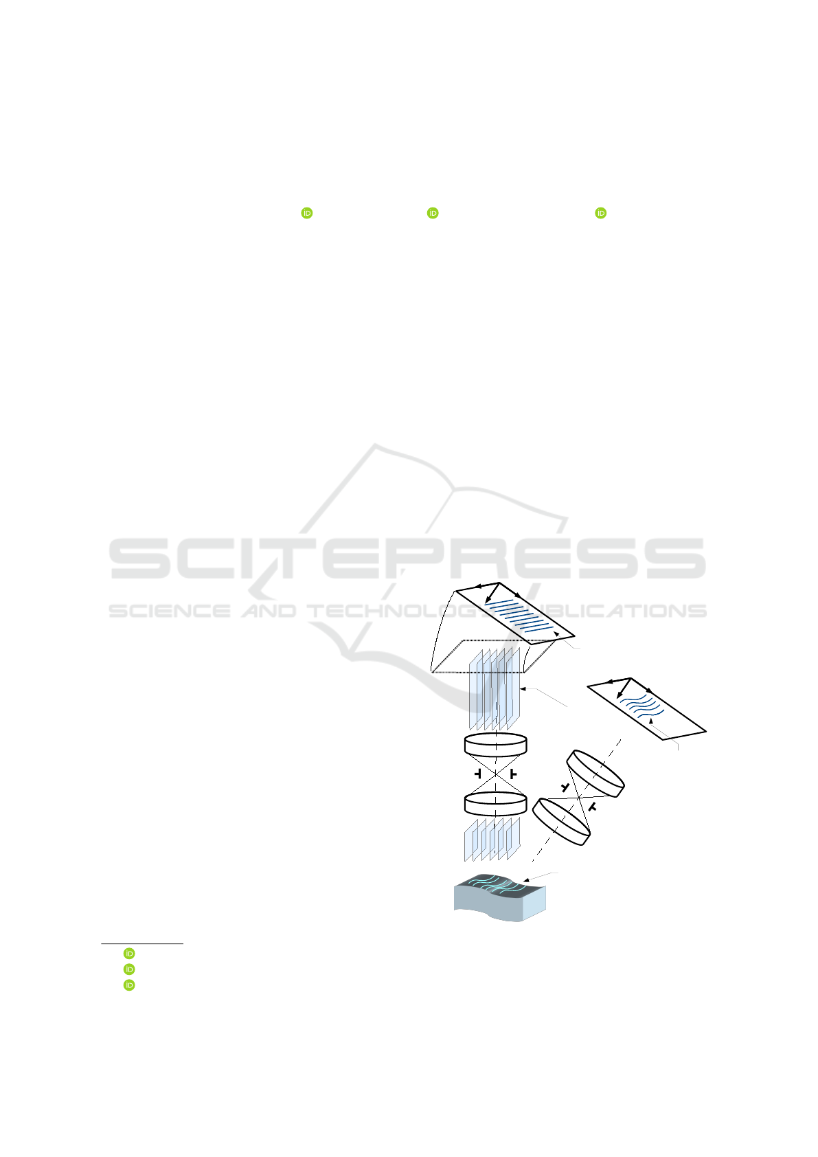
Figure 1: Picture and geometric schema of our telecentric
camera-projector 3D reconstruction device.
440
Pistellato, M., Albarelli, A. and Bergamasco, F.
Calibration of a Telecentric Structured-light Device for Micrometric 3D Reconstruction.
DOI: 10.5220/0010841700003122
In Proceedings of the 11th International Conference on Pattern Recognition Applications and Methods (ICPRAM 2022), pages 440-448
ISBN: 978-989-758-549-4; ISSN: 2184-4313
Copyright
c
2022 by SCITEPRESS – Science and Technology Publications, Lda. All rights reserved

object features’ size ranges from millimetres to mi-
crons. This is the case of several tasks, as quality
control (Weckenmann et al., 2006), weld pool surface
depth measurement (Saeed and Zhang, 2007), lami-
nated plastic wrinkles evaluation (Yao and Xu, 2007),
electrical components or small coins reconstruction
(Li et al., 2014; Liu et al., 2015). Additional exam-
ples include the work presented in (Bergstr
¨
om et al.,
2011; Rosendahl et al., 2010) for an object shape ver-
ification system using structured-light and stereo cor-
respondences, while (Li and Zhang, 2017), proposes
to combine fringe projection with binary defocusing
technique (Lei and Zhang, 2009) for 3D microscopic
profilometry. When the acquisition speed is a limiting
factor, fixed patterns are typically used in the form of
random distributions (Chen et al., 2018) or binary and
coloured codes (Zhou et al., 2017). Shape from single
stripe pattern is proposed in (Winkelbach and Wahl,
2002), where authors devise surface normals from the
stripes observed by a single camera. All the afore-
mentioned applications require an initial calibration
to assess the geometric relations between the compo-
nents involved in the acquisition.
Such process has a direct impact on the quality of
the reconstruction, particularly for industrial-related
applications, where accuracy is a critical requirement.
In the specific case of telecentric surface reconstruc-
tion, the narrow field-of-view of the lenses requires a
specialised method as well as a specifically-designed
calibration target. Common approaches can employ
a small planar target with a grid dot pattern that can
be easily detected and identified by the imaging sys-
tem (Li et al., 2014; Li and Zhang, 2015; Chen et al.,
2014; Bergamasco et al., 2011), complex 3D targets
(Liu et al., 2017), or none (Bergamasco et al., 2014).
In this paper we describe a structured-light de-
vice based on telecentric fringe projection profilom-
etry for micrometic measurements. Our setup com-
bines a telecentric camera and projector with a fixed
pattern composed by equally spaced parallel lines.
Both camera and projector imaging systems are af-
fected by negligible lens distortion and are charac-
terised by an orthographic projection model. The ad-
vantages of employing a single striped pattern are sev-
eral: first, we need a single shot to reconstruct the
scene, thus the acquisition and computation speed are
significantly increased. Moreover, the system does
not require accurate gamma calibration and it does not
suffer from particular scene features like non-uniform
albedo or materials. The contribution is twofold: first,
we propose a novel calibration solution involving the
observation of a sphere with a known radius in differ-
ent positions. The intersections of the parallel planes
generated by the projected pattern with the spherical
surface originate a series of coaxial 3D circles that are
projected as ellipses on the camera image plane. Such
curves can be exploited to geometrically compute the
system parameters and obtain the correct pixel scale
by fitting the 3D sphere. The second contribution con-
sists in a specific case-of-study where the described
sensor is employed to reconstruct the internal surface
of industrial gearwheels. The overall accuracy and
low cost of such approach makes it a potential substi-
tute for the classic contact measuring for quality as-
sessment in industrial applications. Indeed, it is par-
ticularly suitable for the inspection of smooth surfaces
requiring micrometric precision.
2 CALIBRATION TECHNIQUE
Considering their orthographic imaging model, tele-
centric lenses are particularly convenient to measure
small objects. In an orthographic camera the centre
of projection is located at infinity, so that rays com-
ing from the captured object intersect the image plane
orthogonally (Hartley and Zisserman, 2003). This im-
plies that the projection on the image plane is not af-
fected by the object’s depth, and thus the size of each
pixel corresponds to a certain length in the real world,
making straightforward to measure distances along x
and y axes. On the other hand, depth computation and
3D reconstruction are not immediate and require spe-
cialised approaches.
Our device is sketched in Figure 1: the projector
casts on the scene a fixed pattern consisting in a series
of equally-spaced straight lines. Such lines generate
a bundle of equispaced parallel planes P in 3D space,
that are orthogonal to the projector’s image plane. We
define the stride ∆ as the distance between any two
consecutive planes. This value is proportional to the
lines distance on the projector’s image plane, but it is
scaled by a multiplicative unknown factor. Such scale
depends on the combination of (i) the magnifying fac-
tor of the telecentric lens and (ii) the inclination of
the projector’s focus plane (Scheimpflug adjustment),
that needs to be aligned with the camera image plane
to obtain the optimal depth-of-field.
The planes orientation with respect to the camera
coordinate system and their stride are unknown, thus
we identify three parameters that need to be estimated
by the calibration process:
1. the normal vector n =
n
x
n
y
n
z
T
of all the
parallel planes in the bundle P with respect to the
camera reference frame;
2. The scale factor s between camera pixels and the
real world units (i.e. pixel’s size in millimetres).
Calibration of a Telecentric Structured-light Device for Micrometric 3D Reconstruction
441

Figure 2: Left: telecentric projector (in blue) generates a parallel sheaf of planes P intersecting a known sphere used as
calibration target. Such intersections result in coaxial circles in space which (due to self-occlusions) are observed as a set of
arcs by the camera. Right: each circle is projected to the image plane as the ellipse E
i
. The normal n can be obtained by
rotating the vector z around the axis a
i
, but two alternative solutions (n
′
and n
′′
) are equally valid and must be disambiguated.
3. The stride ∆.
All the planes in the bundle are identical, and
therefore is not possible to distinguish their abso-
lute offset (or numbering) within the projector im-
age plane. For this reason, we assume to only recog-
nise their relative order (i.e. which one comes after
another) but not their absolute index with respect to
the first one, which generally depends by the depth
of the observed object. So, without loss of general-
ity, we can assume that P contains an infinite set of
planes P
1
= (p
1
, n), P
2
= (p
2
, n), . . . (parameterised as
a point p
i
and the normal vector n) such that p
i
= ∆ni.
During the calibration process, a sphere with
known radius r is imaged so that a subset of N planes
originated from the projector are cast on the sphere’s
surface. The intersection of parallel planes with with
the sphere generates N circles in 3D space that ex-
hibit some particular properties: (i) they are are coax-
ial since all the slicing planes are parallel, (ii) their
3D centres lie on a line L in space, and (iii) L is
orthogonal to the parallel sheaf of planes (i.e. line
direction has the same orientation as n). Since the
sphere self-occludes the projected light rays, only N
arcs A
1
. . . A
N
of the full circles are visible on the sur-
face. Such N 3D circle arcs are therefore imaged by
the camera as portions of N 2D ellipses E
1
, ..., E
N
. For
each ellipse E
i
with i = 1, ..., N, the plane bundle nor-
mal vector n can be recovered up to two equally pos-
sible configurations.
Let C
i
be the i
th
circle generated by the intersec-
tion of the i
th
plane in P and the sphere. Since we
are using an orthographic camera, C
i
projects to an
ellipse E
i
having a
i
and b
i
as major and minor axes
respectively (see Fig. 2). The length of a
i
is equal
to the radius r of the sphere, so if we rotate the bun-
dle of planes P around the axis a
i
the eccentricity of
E
i
changes. In particular, as shown in (Bergamasco
et al., 2020; Pistellato et al., 2019c), the ratio between
the semi-axes is a function of the angle θ between the
normal n and the camera z-axis:
cos θ =
||b
i
||
||a
i
||
. (1)
In this setting, the bundle normal n can be ob-
tained by rotating the vector z = (0, 0, 1)
T
around the
axis a
i
with two equally possible angles:
θ
1,2
= ± arccos
||b
i
||
||a
i
||
. (2)
As a consequence, each ellipse E
i
generates two
equally possible normal vectors n
′
i
and n
′′
i
. Note that
also −n
′
i
and −n
′′
i
are valid solutions but can be ig-
nored in the disambiguation process since they repre-
sent the same plane.
The 3D line L connecting all the circles’ centres
projects onto the camera image plane as the 2D line l
passing through the ellipses centres. The disambigua-
tion of the correct n exploits the geometry of l to filter
out the wrong plane normals. Indeed, we recall that
n is parallel to the axis L and that all normal vectors
generated by the N ellipses must be oriented to the
same direction. So, among all the alternatives, we
keep the normal vectors whose angles formed with
the axis L is minimum.
Finally, since the ellipses centres are the ortho-
graphic projections of the 3D circles centres, the
stride value can be computed from the relative dis-
tance (in pixels) between adjacent ellipses centres on
the image plane. The relation between such distance
and the stride value is the following:
∆ =
d
sin(β)
(3)
ICPRAM 2022 - 11th International Conference on Pattern Recognition Applications and Methods
442
Inlier Detection
Curve Extraction
and Ellipse Fitting
Calibration
• Stride
• Planes Normal
Triangulation
and Sphere Fitting
Image Acquisition
and Preprocessing
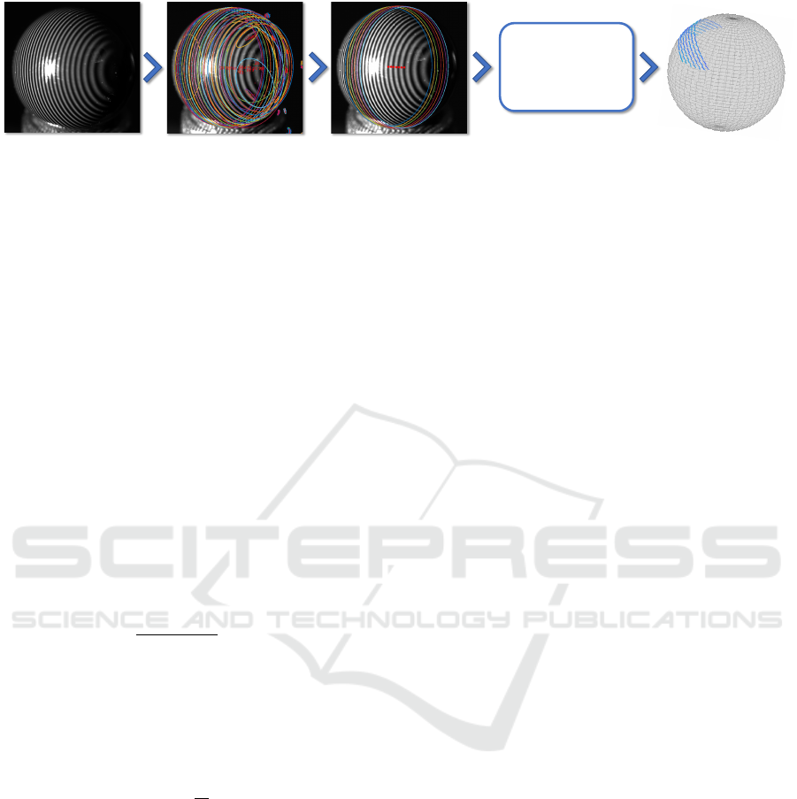
Figure 3: Our proposed calibration pipeline. From left to right: (i) Stripe pattern is projected and a known calibration sphere
is exposed to the camera in different positions. Thresholding, skeletonization, and filtering is applied to cluster each arc. (ii)
Ellipses are robustly fitted to arc points (via RANSAC) and a selection procedure is used to extract a subset of inlier ellipses
whose centers are uniformly distributed on a straight line. (iii) Plane bundle stride and normal is estimated is §2. (iv) 2D arc
points are triangulated by intersecting the corresponding exiting camera rays with the recovered plane bundle. A sphere is
fitted to the obtained 3D points.
where β is the angle formed by the plane normal n
and the camera z-axis, and d is the distance (in cam-
era pixels) between two consecutive projected cen-
tres. Note that, due to the orthographic projection,
this is the equivalent of computing the hypotenuse of
a right-angled triangle.
Once the stride ∆ and plane normal n are com-
puted, points composing the 3D arcs A
1
. . . A
N
can be
triangulated by simply intersecting the exiting cam-
era rays passing through ellipses E
1
. . . E
N
with the
3D planes in P . Let e
j
i
∈ R
2
be the j
th
2D point of
the ellipse E
i
. Its 3D position g
j
i
is given by:
g
j
i
=
(p
i
− e
j
i
)
T
n
n
z
0
0
1
e
j
i
. (4)
The obtained point cloud is then fitted to a sphere
model S, obtaining a radius r
S
, expressed in camera
pixels. Since the acquired sphere has known radius,
the scale between pixels and world units is simply
given by
s =
r
r
S
. (5)
Finally, to obtain a robust parameter estimation
the procedure is repeated for different sphere loca-
tions. The final parameters are computed by aver-
aging the resulting values, excluding the acquisitions
for which the RMS of the distance between the fitted
sphere and the 3D points is above a threshold.
Note that the relative position of the triangulated
points is correct, but their absolute depth can be re-
covered up to an unknown multiple of the stride since
the planes are not distinguishable one from the other.
In other words, matching between a certain 2D point
and the bundle plane from which it was originated
is somehow arbitrary. This is not a showstopper for
many industrial applications, especially when the goal
is to recover the shape of the surface and not its po-
sition, which is often the case with quality assurance.
In cases where the absolute position of the surface is
also needed, it would be straightforward to set an ab-
solute numbering for stripes, for instance by using a
special marker embedded in the pattern.
2.1 Implementation Details
The whole calibration procedure is sketched in Fig-
ure 3. We start by projecting the stripe pattern to
the calibration sphere placed at different random posi-
tions in front of the camera. Stripe contour points are
extracted by applying a series of image filters: first,
5 binary images are obtained by applying 5 differ-
ent threshold levels to the original image. The skele-
tonization for each binary image is computed, as de-
scribed in (Lee et al., 1994), to generate a set of 5 bi-
narized skeleton masks. Then, the skeleton masks are
summed into an accumulator in which morphologi-
cal dilation is applied to join the isolated portions of
each arc (ie. close small holes of the original skele-
ton masks). Finally, the accumulator is thresholded
to extract all the connected components representing
candidate ellipse arcs to be tested.
To provide a reliable an accurate ellipse fitting, we
adopted a RANSAC-based approach as described in
(Halır and Flusser, 1998). We filtered all the ellipses
with less than 80% inliers among the point data, con-
sidering a RANSAC inlier distance of 2 camera pix-
els. In this way, all the extracted arcs that are not
ellipses in the image are automatically discarded.
An additional inlier selection is then performed
over the set of ellipses by fitting a line through their
centres and checking their relative distance in pixels.
Then, the ellipses whose centres are not uniformly
distributed along the line are discarded (See. Alg.1).
In Figure 3 (third image) the inlier ellipses used to
Calibration of a Telecentric Structured-light Device for Micrometric 3D Reconstruction
443
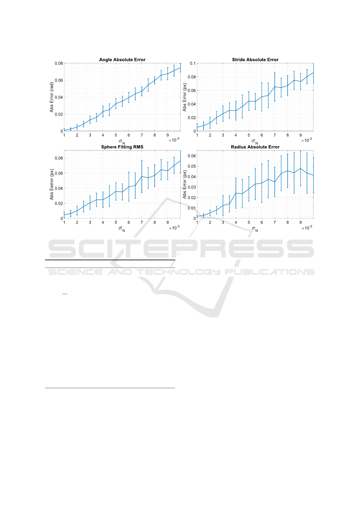
Figure 4: Calibration absolute errors on a synthetic scene. 2D ellipse points are perturbed with a zero-mean Gaussian random
noise with standard deviation σ
N
. For each noise level, the calibration is repeated several times measure the error against the
ground truth.
Algorithm 1: Ellipse inlier detection.
c
1
. . . c
N
← centres of E
1
. . . E
n
fit a line l trough c
1
. . . c
N
via RANSAC
S ← set of indices i such that dist(c
i
, l) < t
l
ˆc =
1
|S |
∑
i∈S
c
i
ˆ
l ← fit a line through points in S
K ← ⟨⟩
for i ∈ S do
ˆc
i
← project c
i
to
ˆ
l
add ˆc
i
in K
end for
Sort points in K according to their signed distance
to ˆc
m ← |K | − 1
Compute ⟨
ˆ
d
1
. . .
ˆ
d
m
⟩ where
ˆ
d
k
= ∥K
k+1
− K
k
∥
D ← median(⟨
ˆ
d
1
. . .
ˆ
d
m
⟩)
Inliers ← points in K s.t. dist(
ˆ
d
i
, D) < t
d
calibrate the system are displayed.
At this point, the selected ellipses are used to com-
pute the plane normal and the stride value as de-
scribed in the previous section. In practice, every el-
lipse gives a independent estimation of n and ∆. We
simply average all such estimations to reduce the er-
ror. Then, the points belonging to the ellipses are tri-
angulated and used to fit a 3D sphere with a standard
linear least-squares approach. Finally, the pixel scale
s is recovered as in (5). Figure 3 (right) shows an
example of the resulting triangulated points and the
corresponding fitted sphere.
3 EXPERIMENTAL EVALUATION
In order to evaluate the performances and the stability
of the proposed method, we designed a set of syn-
thetic and real-world experiments. First, we tested
the accuracy of the parameter estimation from a single
shot, introducing some noise and varying the system
configuration. Then, we exploited our setup to vali-
date the algorithm stability in the case of real-world
applications.
3.1 Synthetic Validation
Synthetic tests give us the full control over the scene,
allowing for a systematic validation of the proposed
technique. We first decided to test the accuracy of
the calibration method against acquisition noise, then
ICPRAM 2022 - 11th International Conference on Pattern Recognition Applications and Methods
444

20 30 40 50 60 70
Projector Angle
0
0.2
0.4
0.6
0.8
Abs Error (rad)
Angle Absolute Error
20 30 40 50 60 70
Projector Angle
2
4
6
8
10
12
14
Abs Error (px)
10
-3
Sphere Fitting RMS
Figure 5: Results on a synthetic scene increasing angle between camera and projector.
we analysed the behaviour of the system varying the
relative position between projector and camera. In our
synthetic tests we simulated a configuration similar
to the real setup, with a virtual orthographic camera
and projector. The projector emits a set of 20 parallel
planes with a fixed stride equal to 0.5 (camera px),
and the camera captures a sphere with a radius equal
to 3 pixels.
In the first experiment we fixed the projector ori-
entation to 45 degrees with respect to the camera z-
axis. Then, we randomized the sphere position (sim-
ulating a real acquisition) and perturbed the projected
2D points of each ellipse with a zero-mean Gaussian
noise with standard deviation σ
N
. Results are shown
in Figure 4, where the absolute errors with respect to
the ground truth are plotted. We increased the error
standard deviation σ
N
applied to 2D points and mea-
sured (i) the angle error with respect the plane nor-
mals, (ii) the stride error, (iii) the sphere radius esti-
mation error, and (iv) the Root Mean Square (RMS)
error of the triangulated points with respect to the
sphere surface.
We repeated each test 100 times, with different
sphere locations, using only one picture to calibrate
the system. As expected, the errors increase linearly
with the noise. In particular, for relatively small per-
turbations, the angle absolute error is smaller than
0.05 radians, and the sphere radius estimation error is
below 0.03 pixels, that is the 2% of the actual radius.
As a second test, we analysed the impact of the
relative angle between the projector and the camera.
Indeed, since the observed portions of ellipses are
fundamental to devise the final system parameters,
we studied such effect on our synthetic setup to de-
sign an optimal configuration for our real-world pro-
totype. To do so, we basically repeated the previous
test, this time varying the relative angle between the
camera and the projector z-axes. Note that with an
angle close to 0 degrees the camera observes straight
lines, because the plane normals are orthogonal to its
z-axis, while when the angle is 90 degrees the camera
should observe circle arcs. Results of this tests are
shown in Figure 5. Interestingly, the projector angle
exhibits a very high impact on the plane normal es-
timation, with an optimal orientation equal to 45 de-
grees. Other measurements are slightly affected by
such angle, as shown for the sphere RMS.
3.2 Real-world Results
In our real-world tests we employed a camera-
projector pair, both equipped with telecentric lenses.
The camera acquires greyscale images with a 12
MPixels resolution, and we used a line pattern with
a physical stride of 0.05 mm. The devices were
mounted on a solid structure with a relative angle of
approximately 45
◦
, in a way that the plane of focus
for both camera and projector are aligned to a com-
mon area of interest (see Fig. 1 and 7). The sphere
used for calibration is a smooth ceramic bearing ball
with a diameter of 8 mm and a declared surface toler-
ance of 0.7 microns.
We evaluated the accuracy and repeatability of the
calibration varying the number of sphere acquisitions.
A total of 30 images were acquired, varying the po-
sition of the sphere in the camera-projector frustum.
Then, we used a cross-validation approach working
as follows. The set of 30 images is divided in m par-
titions. For m times, one partition is used for calibra-
tion and the remaining m − 1 for testing. The opera-
tion is repeated varying the number of partitions (and
consequently the number of image samples used for
calibration, in x-axis) and plotted in Fig.6. Each test
was repeated 20 times, and the standard errors are also
shown as error bars.
We can observe that the normal estimation er-
ror between calibration and test set is in the order
of 4.4 · 10
−3
radians, the stride error lower than 1.5
Calibration of a Telecentric Structured-light Device for Micrometric 3D Reconstruction
445
5 10 15 20
Number of Samples
4.2
4.3
4.4
4.5
4.6
4.7
4.8
Angle Error (rad)
10
-3
Normal Error
5 10 15 20
Number of Samples
0.9
1
1.1
1.2
1.3
1.4
Error (px)
Stride Error
5 10 15 20
Number of Samples
3.2
3.4
3.6
3.8
4
4.2
4.4
4.6
4.8
5
Error (px)
Radius Error
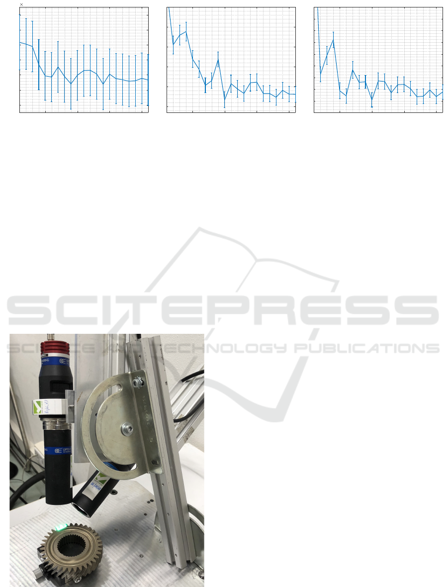
Figure 6: Calibration parameters estimation errors varying the number of acquisitions. From left to right: planes normal
absolute error (rad), stride absolute error (px), and radius error (px).
camera pixels and sphere radius absolute error consis-
tently lower than 4 camera pixels for a number of cal-
ibration samples greater than 5. Moreover, the RMS
of triangulated points over the fitted sphere is below 1
px for the majority of the acquired images. Consider-
ing that the computed scale (ie. the camera pixel size)
s is 3.24 · 10
−3
mm/px, such error is approximately
6.5 microns.
We also tested the 3D reconstruction accuracy by
means of the RMS error between the reconstructed
3D points and the ideal sphere calibration target.
Overall, it ranges from 0.3 to 1.7 pixels, correspond-
ing to 5 microns on average.
Figure 7: Our prototype setup to analyse the internal gear-
wheel’s surfaces.
4 APPLICATION: INDUSTRIAL
SURFACE ANALYSIS
In this section we present an industrial application of
our setup to acquire and analyse the internal gear-
wheel surfaces during the final steps of their produc-
tion (Fig.7).
Gearwheels manufacturing is a field in which pre-
cision and repeatability is critical since the gear’s
teeth need to perfectly fit the shape of other similar
components in a mechanical machinery.
When illuminated by our stripe projector and ac-
quired by the camera, the teeth surface appears as a
semi-shiny material, characterised by diffused micro-
scratches as shown in Fig. 8a.
For this application we first apply a sequence of
image filters so that the line pattern profiles are accu-
rately extracted.
The result of image pre-processing task is shown
in Figure 8b, where each extracted curve is high-
lighted in yellow. For each detected curve, a spline is
fitted and then adjacent curves are identified in order
to enumerate each subsequent projector plane. The
actual teeth reconstruction is carried out by triangu-
lating the detected splines. This is done first by uni-
formly sampling a set of discrete 2D point from each
curve, and then by intersecting each point with the
corresponding plane of P . The procedure generates a
3D point cloud composed by the union of individual
sampled curves, shown in Figure 8c.
Then, adjacent curves are analysed to find point-
to-point correspondences between them. This is per-
formed by running the Iterative Closest Point (Besl
and McKay, 1992) algorithm between two adjacent
curves to find their optimal alignment. The point
matches given by the last iteration of ICP are used to
synthetize additional points by uniform sampling 3D
points on the straight lines connecting them.
Finally, Delaunay 2D triangulation (Chen and
ICPRAM 2022 - 11th International Conference on Pattern Recognition Applications and Methods
446
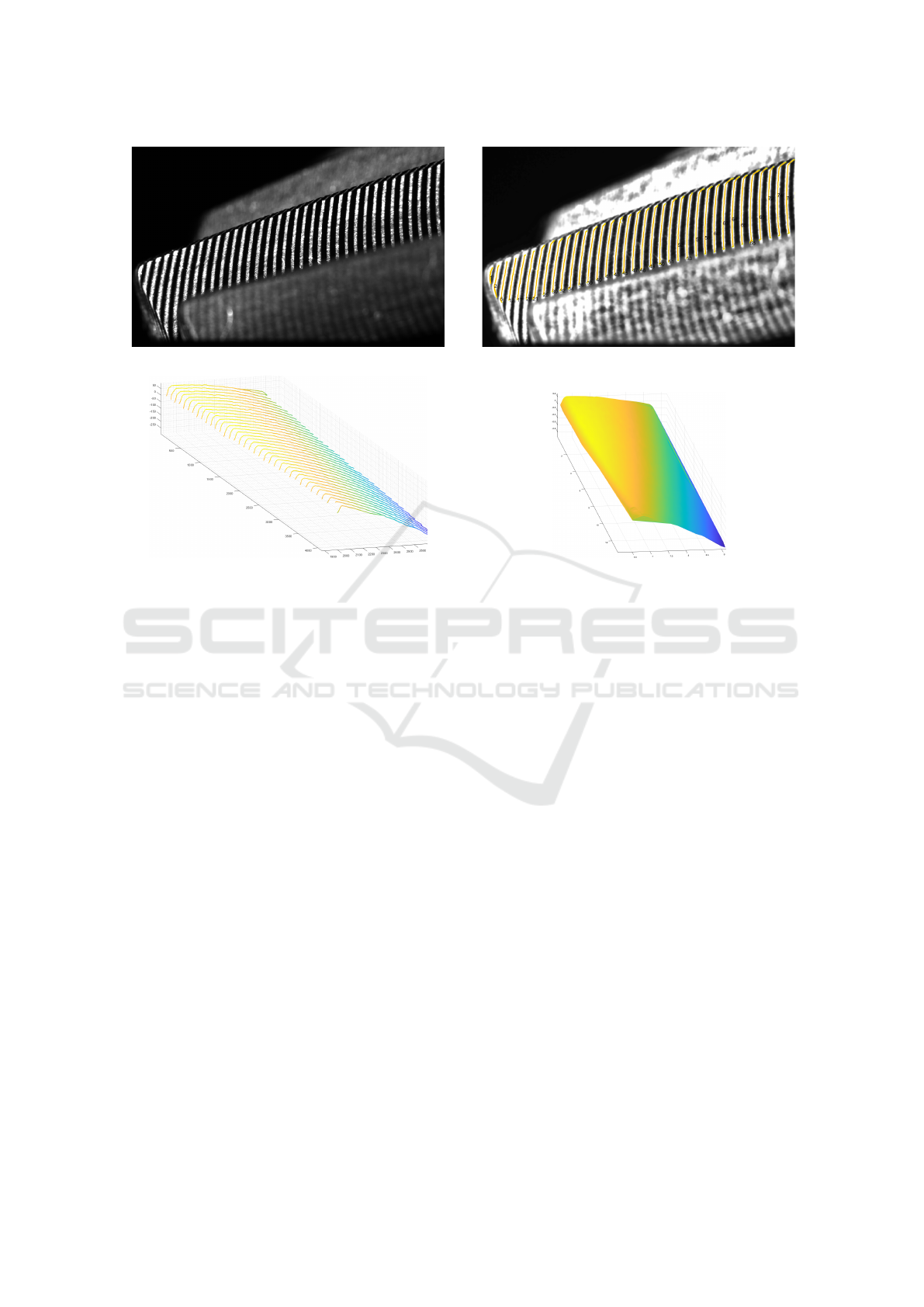
(a) (b)
(c) (d)
Figure 8: Gearwheel teeth analysis. (a) image acquired by the camera. (b) Striped-pattern curve detection. (c) 3D point
cloud obtained by triangulating each stripe. (d) Final tooth surface reconstruction (colour denotes z-coordinate to highlight
the curvature).
Bishop, 1997) is applied to join the 2D points projec-
tions on the camera image plane and obtain a dense
triangulated surface. An example of the final result is
shown in Fig. 8d.
5 CONCLUSIONS
In this paper we proposed a micrometric calibration
process for telecentric camera-projector setups, em-
ploying a fixed-striped pattern. We used a known
spherical target to retrieve the geometrical character-
istics of the system with a precision that can reach the
order of microns. Since such targets are easy to man-
ufacture and not expensive compared to their dimen-
sional accuracy, the whole procedure can be carried
out with a limited effort and costs. Synthetic and real-
world experiments confirm both the stability of our
method and its level of accuracy.
Additionally, we described a case-study of such a
system, by means of a complete pipeline for micro-
scopic surface acquisition and reconstruction involv-
ing micrometric gearwheel surface measurements.
REFERENCES
Bergamasco, F., Albarelli, A., and Torsello, A. (2011).
Image-space marker detection and recognition using
projective invariants. pages 381–388. cited By 14.
Bergamasco, F., Cosmo, L., Albarelli, A., and Torsello,
A. (2014). Camera calibration from coplanar circles.
pages 2137–2142.
Bergamasco, F., Pistellato, M., Albarelli, A., and Torsello,
A. (2020). Cylinders extraction in non-oriented point
clouds as a clustering problem. Pattern Recognition,
107. cited By 1.
Bergstr
¨
om, P., Rosendahl, S., and Sj
¨
odahl, M. (2011).
Shape verification aimed for manufacturing process
control. Optics and Lasers in Engineering, 49(3):403–
409.
Besl, P. J. and McKay, N. D. (1992). Method for registration
of 3-d shapes. In Sensor fusion IV: control paradigms
and data structures, volume 1611, pages 586–606. In-
ternational Society for Optics and Photonics.
Chen, H. and Bishop, J. (1997). Delaunay triangulation
for curved surfaces. Meshing Roundtable, pages 115–
127.
Chen, K., Shi, T., Liu, Q., Tang, Z., and Liao, G. (2018).
Microscopic three-dimensional measurement based
on telecentric stereo and speckle projection methods.
Sensors, 18(11):3882.
Calibration of a Telecentric Structured-light Device for Micrometric 3D Reconstruction
447

Chen, Z., Liao, H., and Zhang, X. (2014). Telecentric stereo
micro-vision system: Calibration method and experi-
ments. Optics and Lasers in Engineering, 57:82–92.
Halır, R. and Flusser, J. (1998). Numerically stable direct
least squares fitting of ellipses. In Proc. 6th Inter-
national Conference in Central Europe on Computer
Graphics and Visualization. WSCG, volume 98, pages
125–132. Citeseer.
Hartley, R. and Zisserman, A. (2003). Multiple view geom-
etry in computer vision. Cambridge university press.
Lee, T.-C., Kashyap, R. L., and Chu, C.-N. (1994). Build-
ing skeleton models via 3-d medial surface axis thin-
ning algorithms. CVGIP: Graphical Models and Im-
age Processing, 56(6):462–478.
Lei, S. and Zhang, S. (2009). Flexible 3-d shape mea-
surement using projector defocusing. Optics letters,
34(20):3080–3082.
Li, B. and Zhang, S. (2015). Flexible calibration method for
microscopic structured light system using telecentric
lens. Optics express, 23(20):25795–25803.
Li, B. and Zhang, S. (2017). Microscopic structured light
3d profilometry: Binary defocusing technique vs. si-
nusoidal fringe projection. Optics and Lasers in En-
gineering, 96:117–123.
Li, D., Liu, C., and Tian, J. (2014). Telecentric 3d profilom-
etry based on phase-shifting fringe projection. Optics
express, 22(26):31826–31835.
Liu, C., Chen, L., He, X., Thang, V. D., and Kofidis,
T. (2015). Coaxial projection profilometry based on
speckle and fringe projection. Optics Communica-
tions, 341:228–236.
Liu, H., Lin, H., and Yao, L. (2017). Calibration method for
projector-camera-based telecentric fringe projection
profilometry system. Optics express, 25(25):31492–
31508.
Pistellato, M., Bergamasco, F., Albarelli, A., Cosmo, L.,
Gasparetto, A., and Torsello, A. (2019a). Robust
phase unwrapping by probabilistic consensus. Optics
and Lasers in Engineering, 121:428–440. cited By 4.
Pistellato, M., Bergamasco, F., Albarelli, A., Cosmo, L.,
Gasparetto, A., and Torsello, A. (2019b). Stochas-
tic phase estimation and unwrapping. pages 200–209.
cited By 0.
Pistellato, M., Bergamasco, F., Albarelli, A., and Torsello,
A. (2015). Dynamic optimal path selection for 3d tri-
angulation with multiple cameras. Lecture Notes in
Computer Science (including subseries Lecture Notes
in Artificial Intelligence and Lecture Notes in Bioin-
formatics), 9279:468–479.
Pistellato, M., Bergamasco, F., Albarelli, A., and Torsello,
A. (2019c). Robust cylinder estimation in point clouds
from pairwise axes similarities. pages 640–647.
Pistellato, M., Cosmo, L., Bergamasco, F., Gasparetto, A.,
and Albarelli, A. (2018). Adaptive albedo compen-
sation for accurate phase-shift coding. volume 2018-
August, pages 2450–2455. cited By 3.
Rosendahl, S., H
¨
allstig, E., Gren, P., and Sj
¨
odahl, M.
(2010). Shape measurement with one fringe pattern
recording including a digital master. Applied Optics,
49(14):2622–2629.
Saeed, G. and Zhang, Y. (2007). Weld pool surface depth
measurement using a calibrated camera and struc-
tured light. Measurement Science and Technology,
18(8):2570.
Weckenmann, A., Peggs, G., and Hoffmann, J. (2006).
Probing systems for dimensional micro-and nano-
metrology. Measurement Science and Technology,
17(3):504.
Winkelbach, S. and Wahl, F. M. (2002). Shape from single
stripe pattern illumination. In Joint Pattern Recogni-
tion Symposium, pages 240–247. Springer.
Xu, J., Xi, N., Zhang, C., Shi, Q., and Gregory, J. (2011a).
Real-time 3d shape inspection system of automotive
parts based on structured light pattern. Optics & Laser
Technology, 43(1):1–8.
Xu, J., Xi, N., Zhang, C., Zhao, J., Gao, B., and Shi, Q.
(2011b). Rapid 3d surface profile measurement of in-
dustrial parts using two-level structured light patterns.
Optics and Lasers in Engineering, 49(7):907–914.
Yao, M. and Xu, B. (2007). Evaluating wrinkles on lami-
nated plastic sheets using 3d laser scanning. Measure-
ment Science and Technology, 18(12):3724.
Zhou, P., Zhu, J., Su, X., Jing, H., and Zhang, X. (2017).
Three-dimensional shape measurement using color
random binary encoding pattern projection. Optical
Engineering, 56(10):104102.
Zuo, C., Feng, S., Huang, L., Tao, T., Yin, W., and Chen,
Q. (2018). Phase shifting algorithms for fringe pro-
jection profilometry: A review. Optics and Lasers in
Engineering, 109:23–59.
ICPRAM 2022 - 11th International Conference on Pattern Recognition Applications and Methods
448
