
A Hybrid System for Real-time Rendering of Depth of Field Effect in
Games
Yu Wei Tan
a
, Nicholas Chua, Nathan Biette
b
and Anand Bhojan
c
School of Computing, National University of Singapore, Singapore
Keywords:
Real-Time, Depth of Field, Ray Tracing, Post-processing, Hybrid Rendering, Games.
Abstract:
Real-time depth of field in game cinematics tends to approximate the semi-transparent silhouettes of out-of-
focus objects through post-processing techniques. We leverage ray tracing hardware acceleration and spatio-
temporal reconstruction to improve the realism of such semi-transparent regions through hybrid rendering,
while maintaining interactive frame rates for immersive gaming. This paper extends our previous work with a
complete presentation of our technique and details on its design, implementation, and future work.
1 INTRODUCTION
We present the design and evaluation of a novel real-
time hybrid rendering approach for the Depth of Field
(DoF) effect which incorporates post-process based
DoF with temporally and spatially reconstructed ray
trace based DoF. By adaptively combining the output
of different passes, we achieve more accurate semi-
transparencies of foreground geometry to reveal back-
ground objects. We believe that our hybrid DoF tech-
nique is the first to integrate a ray-traced output with
a traditional post-processing pipeline.
Building on our previous work (Tan et al., 2020a),
the key contributions of this paper are as follows.
• Design and implementation of a real-time hybrid
rendering pipeline for DoF.
• Visual quality evaluation of the hybrid method,
specifically, the accuracy of semi-transparencies.
• Performance evaluation and trade-offs in the use
of ray tracing for DoF.
1.1 Background Information
Current DoF implementations in game engines
typically use the thin lens model (Potmesil and
Chakravarty, 1982) to approximate the behaviour of
cameras. The zone of focus is the part of the scene
where the objects look sharp. The Circle of Confu-
sion (CoC) (Demers, 2004) of points in the zone of
a
https://orcid.org/0000-0002-7972-2828
b
https://orcid.org/0000-0001-7827-1538
c
https://orcid.org/0000-0001-8105-1739
focus are smaller than a cell on the sensor, yielding a
single pixel in the image, whereas points outside the
zone of focus appear as a spot on the image based on
their CoC. For such points which lie on the same ob-
ject, an overall blur of the object is produced.
Bokeh shapes, which are bright spots created by
a beam of unfocused light hitting the camera sensor,
appear in areas out of the zone of focus. They usu-
ally take the shape of the camera’s aperture and can
have circular or polygonal frames depending on the
number of blades in the camera shutter.
Blurred foreground objects also have a slightly
transparent silhouette through which background
colour can be observed. These semi-transparent edges
cannot be properly rendered in games with post-
processing as the image does not store any informa-
tion behind a foreground object (Kraus and Strengert,
2007). However, such approaches are widely used in
real-time rendering as images produced by rasteriza-
tion are in sharp focus (McGraw, 2015). According to
Jimenez (2014), many techniques can only perform
an approximation of the background colour locally
using neighbouring pixels like in Abadie (2018) or
grow blur out of the silhouette of foreground objects
onto background colour, reusing foreground informa-
tion to avoid reconstructing the missing background.
However, shifting the blur outwards from foreground
objects produces inaccuracies with regards to their ac-
tual geometries, especially when the amount of ex-
tended area is comparable to the size of the objects
themselves. Objects with more elaborate shapes also
become fat and deformed at areas with large CoC.
Nonetheless, such inaccuracies do not exist in ray-
Tan, Y., Chua, N., Biette, N. and Bhojan, A.
A Hybrid System for Real-time Rendering of Depth of Field Effect in Games.
DOI: 10.5220/0010839800003124
In Proceedings of the 17th International Joint Conference on Computer Vision, Imaging and Computer Graphics Theory and Applications (VISIGRAPP 2022) - Volume 1: GRAPP, pages
79-90
ISBN: 978-989-758-555-5; ISSN: 2184-4321
Copyright
c
2022 by SCITEPRESS – Science and Technology Publications, Lda. All rights reserved
79

traced DoF (Cook et al., 1984) as we can simulate
a thin lens and query the scene for intersections, not
being limited to what is rendered in the rasterized im-
age. Nonetheless, achieving interactive frame rates
with ray tracing is difficult due to the high computa-
tional costs of calculating ray-geometry intersections
and multiple shading for each pixel, even with the lat-
est GPUs developed for ray tracing. Hence, hybrid
rendering, which aims to combine existing rasteriza-
tion techniques with ray tracing, is being researched.
2 RELATED WORK
2.1 Hybrid Rendering
Examples of hybrid rendering on related effects in-
clude Macedo et al. (2018) and Marrs et al. (2018)
which invoke ray tracing for reflections and anti-
aliasing respectively only on pixels where rasteri-
zation techniques are unable to achieve realistic or
desirable results. Beck et al. (1981), Hertel et al.
(2009) and Lauterbach and Manocha (2009) employ
the same strategy to produce accurate shadows.
The concept of hybrid rendering can also be ex-
tended to general rendering pipelines. For example,
Cabeleira (2010) uses rasterization for diffuse illu-
mination and ray tracing for reflections and refrac-
tions. Barr
´
e-Brisebois et al. (2019) is also one such
pipeline that has replaced effects like screen-space re-
flections with their ray trace counterparts to achieve
better image quality. Another commonly-used ap-
proach is Chen and Liu (2007), the substitution of
primary ray generation with rasterization in recursive
ray tracing by Whitted (1979). Andrade et al. (2014)
improves upon this technique by observing a render
time limit through the prioritization of only the most
important scene objects for ray tracing.
2.2 DoF
Many DoF rendering techniques have been devised
over the years. Potmesil and Chakravarty (1982)
first introduced the concept of CoC for a point based
on a thin lens model which simulates the effects of
the lens and aperture of a physical camera. It em-
ploys a post-processing technique that converts sam-
pled points into their CoCs. The intensity distribu-
tions of CoCs overlapping with each pixel are then
accumulated to produce the final colour for the pixel.
Haeberli and Akeley (1990) integrates images ren-
dered from different sample points across the aper-
ture of the lens with an accumulation buffer. On the
other hand, Cook et al. (1984) traces multiple rays
from these different sample points on the lens into the
scene using a technique now commonly known as dis-
tributed ray tracing, for which improvements in ray
budget have been made in Hou et al. (2010) and Lei
and Hughes (2013).
For rendering with real-time performance con-
straints, spatial reconstruction and temporal accumu-
lation approaches have also been developed. For in-
stance, Dayal et al. (2005) introduces adaptive spatio-
temporal sampling, choosing to sample more based
on colour variance in the rendered image with selec-
tive rendering by Chalmers et al. (2006) and favouring
newer samples for temporal accumulation in dynamic
scenes. Schied et al. (2017) also uses temporal ac-
cumulation to raise the effective sample count on top
of image reconstruction guided by variance estima-
tion. Such techniques have been applied for DoF such
as in Hach et al. (2015), Leimk
¨
uhler et al. (2018),
Weier et al. (2018), Yan et al. (2016) and Zhang et al.
(2019). More advanced reconstruction techniques for
DoF have also been introduced, such as Belcour et al.
(2013), Lehtinen et al. (2011), Mehta et al. (2014) and
Vaidyanathan et al. (2015) which sample light fields
as well as Shirley et al. (2011) which selectively blurs
pixels of low frequency content in stochastic sam-
pling. A more adaptive temporal accumulation ap-
proach from Schied et al. (2018) which is responsive
to changes in sample attributes such as position and
normal has also been proposed to mitigate ghosting
and lag in classic temporal accumulation approaches.
Micropolygon-based techniques have also proven
to be capable of DoF like in Fatahalian et al. (2009)
and Sattlecker and Steinberger (2015). Catmull
(1984) solves for per-pixel visibility by performing
depth sorting on overlapping polygons for each pixel.
Following this, approaches based on multi-layer im-
ages like Franke et al. (2018), Kraus and Strengert
(2007), Lee et al. (2008), Lee et al. (2009) and Sel-
grad et al. (2015) have also been introduced where
the contributions from each layer are accumulated to
produce the final image. Such layered approaches
are computationally expensive although they can gen-
erate relatively accurate results in terms of semi-
transparencies. Bukowski et al. (2013), Jimenez
(2014), Valient (2013) and state-of-the-art Unreal En-
gine approach Abadie (2018) divide the scene into the
background and foreground, and runs a gathering fil-
ter separately for each. We adopt such a technique,
which performs better in terms of rendering time even
in comparison to Yan et al. (2016), which avoids the
problem of separating the scene by depth by factoring
high-dimensional filters into 1D integrals.
Hach et al. (2015) acquires a rich lens archive de-
rived from a real target cinematic lens and uses it to
GRAPP 2022 - 17th International Conference on Computer Graphics Theory and Applications
80

synthesize a point spread function (PSF) for convo-
lution in blurring. For each pixel, Leimk
¨
uhler et al.
(2018) splats its PSF using a sparse representation
of its Laplacian. Time-dependent edge functions for
Akenine-M
¨
oller et al. (2007) and complex plane pha-
sors for Garcia (2017) have also been used to pro-
duce DoF. Such approaches involve complex compu-
tations and seem to be more suitable for offline ren-
dering. More recently, convolutional neural network
approaches like Zhang et al. (2019) perform post-
processing for DoF by predicting the amount of blur
to generate through the analysis of past frames in real-
time but require copious amounts of training data.
McGraw (2015) and McIntosh et al. (2012)
are post-process techniques that produce polygonal
bokeh shapes based on the silhouette of the camera
aperture. McGraw also supports bokeh shapes of non-
uniform intensities, including bokeh shapes which are
lighter or darker at the rim due to spherical aberration
of the lens. Our approach currently generates circu-
lar bokeh shapes of uniform intensities but can be ex-
tended to produce alternative bokeh shapes such as
polygons by changing the shape of our sampling ker-
nel, and bokeh shapes of varying intensities by adjust-
ing the relative weight of samples within the kernel.
Our hybrid DoF technique is novel as we augment
conventional post-process approaches with ray trac-
ing, generating more accurate semi-transparencies of
foreground geometry in real-time.
3 DESIGN
Our approach in Figure 1 combines post-process
based DoF with temporally-accumulated and
spatially-reconstructed ray trace based DoF, to
produce a hybrid DoF effect that recreates accurate
semi-transparencies. Using deferred shading, a Ge-
ometry Buffer (G-Buffer) is first produced, together
with textures containing other derived information
needed for the post-process and ray trace stages. A
sharp all-in-focus rasterized image of the scene is
also generated. This image subsequently undergoes
post-process filtering while parts of the scene deemed
inaccurate with post-processing undergo distributed
ray tracing augmented with spatio-temporal recon-
struction. The images are finally composited together
with a temporal anti-aliasing (TAA) pass.
We split our scene into the near field and the far
field. Points in the scene in front of the focus plane
are in the near field, and points behind the focus plane
are in the far field further away, as shown in Figure 2.
We perform this split for both the post-process and ray
trace images, in order to merge post-processed colour
with ray trace colour on a per-field basis later on.
3.1 Post-process
For our post-process technique, we adapted the DoF
implementation by Jimenez (2014) which uses a gath-
ering approach directly inspired by Sousa (2013) for
filtering to produce blur. Following Jimenez, the ini-
tial rasterized image is downscaled to half its resolu-
tion to speed up the filtering process.
3.1.1 Prefilter Pass
For circular bokeh shapes, Jimenez uses a 49-tap 3-
ring main filter kernel scaled to the size of the max-
imum CoC in the tile neighbourhood of the target
pixel. However, to fight undersampling, a downsam-
pling 9-tap bilateral prefilter is first applied to fill the
gaps of the main filter. We decided to use 81 taps with
an additional ring of samples as shown in Figure 3 for
better visual quality. Hence, our prefilter kernel has
a diameter of 1/8 instead of 1/6 the maximum CoC
size as in the original design. In cases where the max-
imum CoC is too small as most pixels in the neigh-
bourhood are in focus, the size of the prefilter kernel
is capped at
√
2 (diagonal length of 1 pixel) to avoid
sampling the same pixel multiple times.
3.1.2 Main Filter Pass
Jimenez performs alpha blending on the foreground
and background layers with the normalized alpha of
the foreground. However, the implementation result
was unsatisfactory as the normalized alpha calculated
was too small, producing an overly transparent fore-
ground. Hence, we used a normalized weighted sum
of foreground and background contributions for the
post-process colour v
p
instead as shown.
v
p
=
v
f
+ v
b
∑
81
i=1
D(0, i) ·sampleAlpha(r
i
)
(1)
In the above equation, r
i
refers to the CoC radius
of sample i while v
f
and v
b
represent the total ac-
cumulated colour for the foreground and background
respectively. D(0,i) refers to the comparison of the
CoC of sample i to its distance to the centre tap of the
kernel. If the radius of the sample’s CoC is greater
than its distance to the kernel centre, the sample con-
tributes to the target pixel’s colour.
To combat aliasing, we jitter the camera’s position
with pseudorandom number values. We also gather
the proportion of samples with high specular values
for each pixel to be used to composite ray trace and
post-process colour on bright bokeh shapes later on.
A Hybrid System for Real-time Rendering of Depth of Field Effect in Games
81
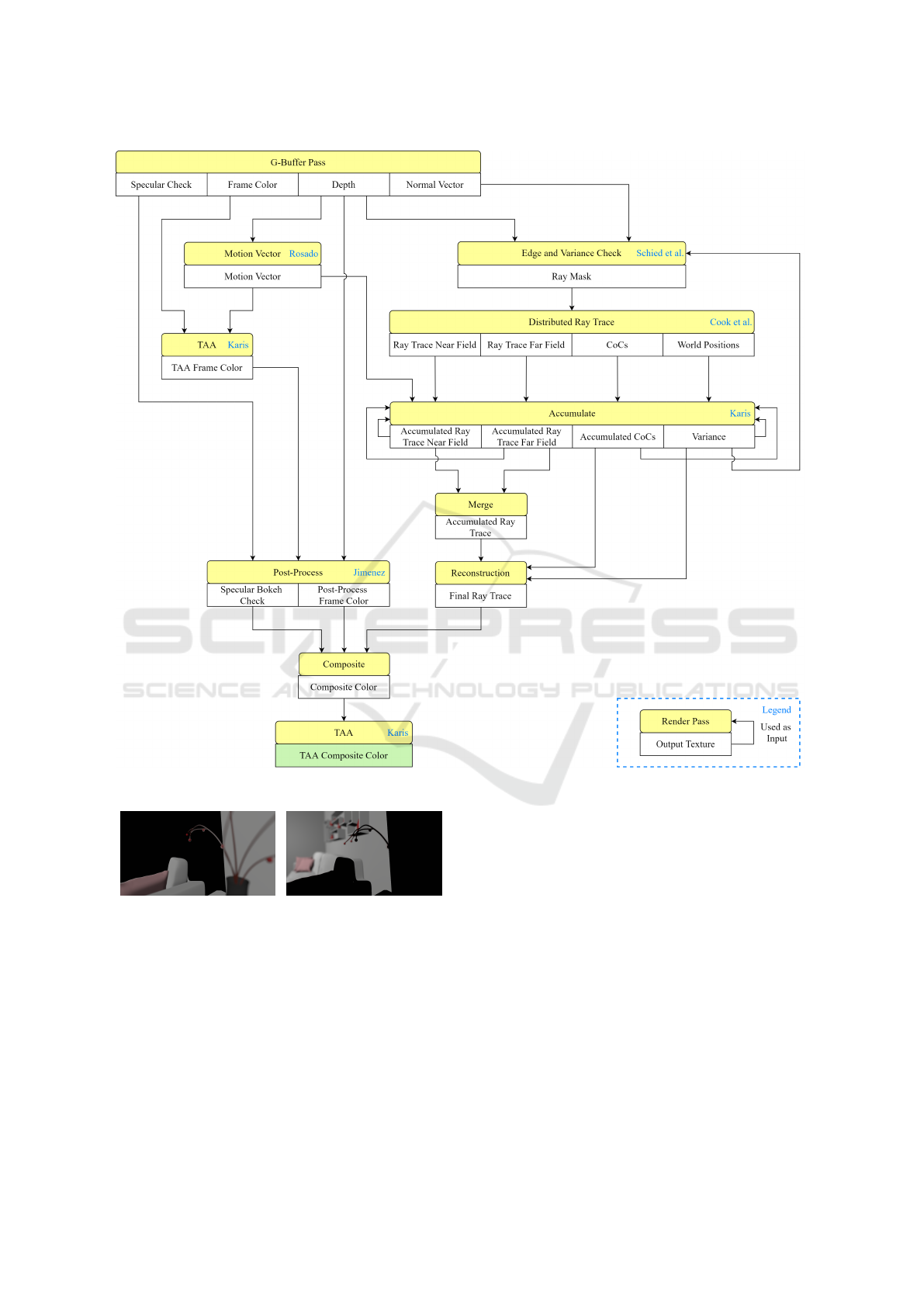
Figure 1: Hybrid rendering pipeline for DoF.
(a) Near field (b) Far field
Figure 2: Demarcation of near and far fields.
3.1.3 Postfilter Pass
Finally, as recommended by Jimenez, we apply a
3 ×3 median postfilter at half resolution to upscale
the image back to full resolution like in Sousa (2013).
The median postfilter, based on a GPU-optimized
max-min network flow (Smith, 1996), helps to re-
move noise from the main pass filtering by rejecting
outlier pixels, smoothening out the result.
3.2 Ray Trace
3.2.1 Ray Mask
We shoot a variable number of rays into the scene by
creating an adaptive ray mask based on the gradient of
surface normals. Employing a selective rendering ap-
proach (Chalmers et al., 2006) for better performance,
we aim to shoot more rays at edges to create clean
semi-transparencies but less at regions with fewer de-
tails such as relatively flat surfaces.
Our ray mask utilizes a 5 ×5 Sobel convolution
kernel to estimate how extreme an edge is. Adopt-
ing ideas from Canny Edge Detection (Canny, 1986),
we apply a Gaussian filter on the G-Buffer before per-
forming the Sobel operator so as to reduce noise and
jaggies along diagonal edges. The Sobel kernel is
GRAPP 2022 - 17th International Conference on Computer Graphics Theory and Applications
82
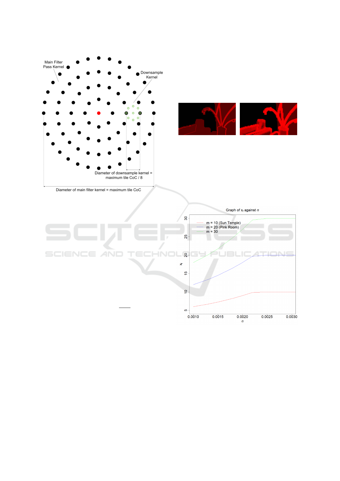
Figure 3: 9-Tap bilateral prefilter for 81-tap main filter.
then applied to the filtered G-Buffer at a lower reso-
lution to get an approximate derivative of the gradient
associated with each target pixel, based on the depth
and surface normal of itself and surrounding pixels
which are readily available from rasterization. The
depth derivatives capture the separation between over-
lapping objects where the colour of one object might
be uncovered in the other. On the other hand, normal
derivatives can detect significant variations in the ori-
entation of primitive faces within objects themselves
near their silhouettes, where semi-transparencies are
observed in DoF. The per-pixel output of this filter is:
x = (δ
d
+ δ
n
) ·s, s ∈ [0,1] (2)
x
n
= saturate(1 −
1
x + 1
) (3)
Here, δ
d
and δ
n
refer to the magnitude of the
derivative of depth and surface normals surrounding
the pixel respectively, based on the Sobel filter. x
n
refers to the normalized x and s is a user-specified
variable to scale down the result as it is hard to per-
form normalization with respect to the entire scene,
resulting in the aforementioned compromise.
To account for temporal variation to reduce noise
in the output, we also shoot more rays at regions
of high variance in luminance as inspired by Schied
et al. (2017). Hence, the ray mask is complemented
with a temporally-accumulated variance estimate σ
2
explained later in Section 3.2.3. Although this vari-
ance is small, it is able to detect edges of foreground
objects and specular bokeh shapes. We favour shoot-
ing more rays in these regions for a cleaner image via
scaling the variance by a large weight of 100000. This
amplified variance is then used with x
n
to determine
the final ray count as follows.
x
f
= saturate(x
n
+ σ
2
·100000) ·m (4)
(a) σ
2
·100000
(b) x
f
Figure 4: Comparison of variance with no. of rays shot.
The value of the large weight was chosen with our
observation of the final ray mask generated in relation
to our variance as shown in Figure 4. Instead of se-
lectively updating specific pixels like in Dayal et al.
(2005), we shoot at least one ray per pixel in the near
field but increase this number based on the variance
gathered over time for enhanced visual quality.
Figure 5: Graph of x
f
against σ for different m at x
n
= 0.5.
The number of rays to be shot per pixel is capped
at m, a scene-dependent value that can be tuned for
performance or accuracy. Appropriate values were
chosen for scenes SUN TEMPLE and PINK ROOM.
As shown in Figure 5, more rays are shot as the esti-
mated luminance variance increases. However, after a
certain threshold, this number plateaus and never ex-
ceeds m which is exactly the ray budget for the scene.
A Hybrid System for Real-time Rendering of Depth of Field Effect in Games
83

3.2.2 Shooting Rays
We follow the distributed ray tracing DoF technique
by Cook et al. (1984) in shooting a ray from a point
on the lens to a calculated focus point. We consider
the final image as the camera sensor and the position
of the camera in the scene as the centre of the lens.
After determining the direction from a pixel on
the “sensor” (the image being rendered) to the cen-
tre of the lens, we then compute the focus point of
this pixel on the focus plane. Then, we take ran-
dom positions on the lens and spawn rays from those
positions towards the focus point. As illustrated in
Kraus and Strengert (2007), we take multiple samples
within a circle to produce random ray origins within
the lens’ area. On edges of foreground objects, some
rays will hit the object while others will “go around”
and sample the scene behind, yielding the effect of
semi-transparent silhouettes of the blurred object in
the foreground, out of the zone of focus.
We ray trace at half resolution as a trade-off for
speed and upscale later using the same median filter
as our post-process stage in Section 3.1.3, helping to
reduce sampling noise especially on very bright ar-
eas of foreground objects. The ray-traced colours and
their respective calculated CoC sizes are then sorted
by depth into the near and far field. To have a smooth
transition between the near and far field, we split the
contribution of each ray trace colour per pixel to each
field based on its distance from the separating focus
plane. A hit ratio is also stored, which is the number
of rays contributing to the near field colour divided by
the total rays shot.
3.2.3 Accumulation and Reprojection
To increase our sample count, we use temporal accu-
mulation adapted from TAA (Karis, 2014). We ac-
cumulate the near and far field ray trace colours over
time and use an exponential moving average to blend
between history and current frames. By default, we
use a high blend factor of 0.95 to stabilize the image.
However, to account for movement, we leverage
per-pixel depth and motion information for reprojec-
tion like in Lehtinen et al. (2011). As such, we use
motion vectors calculated based on Rosado (2008) to
reproject near field pixels. As for the far field, we re-
quire an approximation of the far field world position
of our target pixel. We first attempt to compute the av-
erage world position of our target pixel from far field
hits of our ray trace pass. Under low ray counts, in the
event that there is no far field hit, the target pixel does
not give any depth information for far field reprojec-
tion. In such cases, we obtain the average far field
world position of neighbouring pixels in a 3×3 region
instead. Then, we use the computed world position
to calculate the previous screen space position of the
target pixel. This approximates reprojection for oc-
cluded objects appearing in semi-transparent regions.
Since reprojection is different for the near and far
fields, we normalize the final colour based on the ac-
cumulated hit ratio h. Otherwise, we run the risk of
having varying colour intensities in our merged result.
Hence, we perform linear interpolation (lerp) on the
near and far field colours based on h. We also lerp the
new average near and far field CoC sizes accordingly
to get an approximate CoC size for the current frame
for spatial reconstruction later. However, during mo-
tion, we lerp based on the latest hit ratio rather than h
to prevent the ghosting (or smearing) of the far field
within the silhouette of near field objects.
Like Dayal et al. (2005), we sample more for ar-
eas of large colour variance. Borrowing from Schied
et al. (2017), we calculate variance estimates using lu-
minance values of the final merged ray trace image to
identify regions of high noise. This includes specular
bokeh shapes that are difficult to converge as well as
newly ray-traced regions. The variance texture then
undergoes a Gaussian blur before it is used to deter-
mine the number of rays to be shot in the next frame.
3.2.4 Spatial Reconstruction
Before spatial reconstruction, the ray trace colour is
median filtered (Section 3.1.3), which helps to re-
move sparse unconverged bokeh shapes formed by
small specular highlights, trading accuracy for im-
age quality. For reconstruction, we use a circular
kernel to gather the surrounding colour contributions
of neighbouring pixels. The kernel is scaled for
sampling using the average CoC size of the current
frame collected from temporal accumulation, which
is also used to determine the mip level or level-of-
detail (LOD) for the sampling. Samples with CoC
radius smaller than their distance to the target pixel
are rejected, similar to the post-process filtering ap-
proach as described earlier. Finally, we lerp the orig-
inal colour and hit ratio of the target pixel with that
of its neighbours by clamped variance estimates b to
avoid over-blurring in converged regions, as shown in
the equation below.
b = clamp(σ
2
·2000, 0, 0.9) (5)
In the above equation, we are calculating how ag-
gressive our variable size blur is for the ray-traced
output. The variance is scaled by a large weight of
2000 to blur any pixels with a small variance. Once
again, this value is chosen based on observation of
output as opposed to physically correct rendering.
GRAPP 2022 - 17th International Conference on Computer Graphics Theory and Applications
84

3.3 Composite
For the final image, we apply the ray trace, post-
process and sharp rasterized colours onto pixels based
on their z-distances in relation to the zone of focus.
To determine the depth range of the zone of focus, we
first compute the range for which the CoC size of pix-
els is less than
√
2. If the CoC of a point is smaller
than a “pixel” on our camera sensor (or a sensor cell),
it will appear as a single pixel in the final image and
can be considered in focus. Hence, we determined
that the zone of focus is the set of z-values where:
a · f ·d
(a · f +
√
2(d − f ).
w
s
w
i
)
≤z ≤
a · f ·d
(a · f −
√
2(d − f ) ·
w
s
w
i
)
(6)
Here, a refers to the aperture diameter of the cam-
era lens, f its focal length, d the distance between the
lens and the focus plane, w
s
the sensor’s width in met-
ric units and w
i
the image’s width in pixels.
Within the zone of focus, the full resolution un-
blurred rasterized colour is applied instead of the fil-
tered ray trace or post-process colours upscaled from
half resolution. Outside the zone of focus, for near
field objects and their silhouettes, we then apply the
ray trace colour to form accurate semi-transparent
silhouettes. However, for bright bokeh shapes, we
favour the post-process over the ray trace colour based
on the bokeh shape intensity, i.e., the proportion of
samples with high specular values gathered from the
main filter pass of the post-process stage. Through
this, we minimize noise and ghosting artifacts from
the ray trace colour in specular bokeh shapes.
For far field geometry out of the zone of focus, we
adaptively blend the ray trace colour with the post-
process colour using the hit ratio. If the hit ratio is
high, we favour the post-process colour as fewer rays
hit the far field. On the other hand, if the hit ra-
tio is low, this means that the number of hits in the
far field is comparable to that of the near field, so
more ray trace colour is used. However, there are also
fewer foreground hits closer to the edges of the ray
mask. Hence, when blending ray trace colour with
post-process colour, using our hit ratio as-is causes
blur discontinuities and tiling artifacts from our ray
mask. To minimize them while trying to retain the
ray-traced semi-transparencies, we only blend at hit
ratios below 0.3 to produce a smooth transition be-
tween the ray trace and post-process colours, as illus-
trated in the formula below. If we bias towards the
post-process colours (> 0.3), we will lose the semi-
transparencies rendered by our ray trace pass.
h = smoothstep(0, 0.3, h) (7)
3.4 TAA
Fireflies are artifacts appearing due to the sampling
of very bright pixels which get spread out during spa-
tial low-pass filtering but are not temporally stable.
As the camera moves, the bright spots tend to flicker
from one frame to another. This persistent flickering
is likely due to the temporal instability of the initial
rasterized image. Because of its low-pass filtering
stages, post-processed DoF is particularly sensitive to
pixel flicker and will tend to spread the small tempo-
rally unstable highlights, creating fireflies artifacts.
Following the example from Abadie (2018) to re-
move flickering bright pixels, we resolve our final im-
age with TAA (Karis, 2014), reprojecting previous
frames onto the newest frames. To further stabilize
our result, we also apply TAA to the initial rasterized
image before filtering, as well as to the image gener-
ated after filtering to stabilize camera jitter.
4 IMPLEMENTATION
4.1 Falcor
We used the NVIDIA Falcor real-time rendering
framework (Benty et al., 2020) with DirectX 12 back-
end to utilize ray tracing acceleration and develop our
hybrid DoF pipeline. We also made use of Falcor’s
graphics techniques library to apply Gaussian blur on
our G-Buffer and luminance variance in generating
our ray mask, as well as TAA to stabilize our result.
4.2 Scene-dependent Values
The scenes used for testing our hybrid DoF imple-
mentation are THE MODERN LIVING ROOM (Wig42,
2014) and UE4 SUN TEMPLE (Epic Games, 2017).
We also tested our approach on AMAZON LUMBER-
YARD BISTRO (Amazon Lumberyard, 2017).
For all 3 scenes, we used s = 0.8 for scaling in
our ray mask as it worked well to identify edges
when coupled with our variance estimation. Increas-
ing the value would bias to shooting more rays even
at relatively flat surfaces. For THE MODERN LIVING
ROOM (or PINK ROOM), maximum ray values m of
10 to 20 per pixel worked well. Increasing the number
of rays had diminishing returns for the visual quality
of bokeh shapes. For SUN TEMPLE and the exterior
scene of AMAZON LUMBERYARD BISTRO (BISTRO
EXTERIOR), we had to keep our maximum ray count
at 10 to get interactive frame rates for large ray masks.
However, as SUN TEMPLE and BISTRO EXTERIOR
A Hybrid System for Real-time Rendering of Depth of Field Effect in Games
85
are more complex with textures, any noise observed
was less noticeable as compared to PINK ROOM.
Regarding the depth range for our post-process
main filter pass, as compared to 100 feet as suggested
by Jimenez, we found that a value of 10 cm worked
best for our test scenes due to their relatively close
geometries. As for our mip sampling in spatial recon-
struction, we used a simple clamped linear mapping
to determine the LOD to sample from, as illustrated in
the formula below, where c
t
refers to the temporally-
accumulated CoC of each pixel. This linear mapping
was devised from our observation of the amount of
blur in specular bokeh shapes for our test scenes.
lod = clamp(c
t
·0.05, 0, 3) (8)
We hope to further simplify these scene-
dependent variables for ease of use by artists.
5 RESULTS
5.1 Graphics Quality Comparison
We evaluate our hybrid DoF method (c) against our
adaptation of fully post-processed DoF (Jimenez,
2014) without local background reconstruction (a),
Unreal Engine 4 DoF (Abadie, 2018) (b) and fully
ray-traced DoF (Cook et al., 1984) (d) in this section
as well as our demo video (link).
(a) (b) (c) (d)
Figure 6: Semi-transparencies of foreground silhouettes.
Semi-transparencies are of much better quality
with hybrid DoF, as seen in Figure 6. For the adapted
post-process DoF, the foreground blur is extended out
of the object’s silhouette to overwrite the background
colour. However, in hybrid DoF, we can see the back-
ground object, specifically, the bottom right corner of
the cushion appear along the edge of the cushion in
front. This same corner is not visible for UE4.
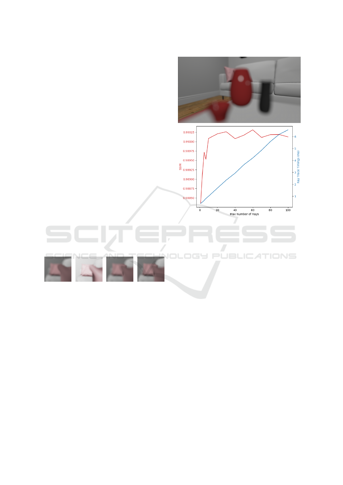
To quantitatively compare the visual quality of our
hybrid result with the ground truth (Cook et al., 1984),
we chose a shot of PINK ROOM with very blurred
foreground geometry that exhibits highly specular
bokeh shapes and semi-transparent silhouettes in Fig-
ure 7. When compared to ground truth DoF, increas-
ing the maximum number of rays of hybrid DoF for
the shot at relatively low ray counts increases the
structural similarity index (SSIM), suggesting that our
Figure 7: Top: reference image at m = 10. Bottom: graph
of SSIM and ray trace pass timings against ray budget m.
reconstruction filter might be effective in improving
image quality. However, at higher ray counts, there
are diminishing returns. At this stage, our technique is
also unable to reach ground truth quality even at high
ray counts, due to some approximated values used in
our post-process stage and composition artifacts.
5.2 Performance
Using the Falcor API helped speed up implementa-
tion by handling the loading of scene assets, setting
up the rendering pipeline and creating ray tracing ac-
celeration structures. However, the API hides many
low-level details from Direct3D, making it difficult to
optimize rendering. Consequently, frame rate figures
are not representative of how our algorithm would
perform if professionally implemented and properly
optimized for games. Nonetheless, we believe that
our technique can be adapted and optimized for in-
teractive rendering and motivate further research in
this direction. We have achieved relatively interactive
frame rates without extensive optimization, validating
hybrid rendering as a proof of concept.
Our measurements are taken with the Nsight pro-
filing tool on an Intel Core i7-8700K CPU at 16GB
RAM with an NVIDIA GeForce RTX 2080 Ti GPU.
The shots used include a background-dominant (BG)
GRAPP 2022 - 17th International Conference on Computer Graphics Theory and Applications
86
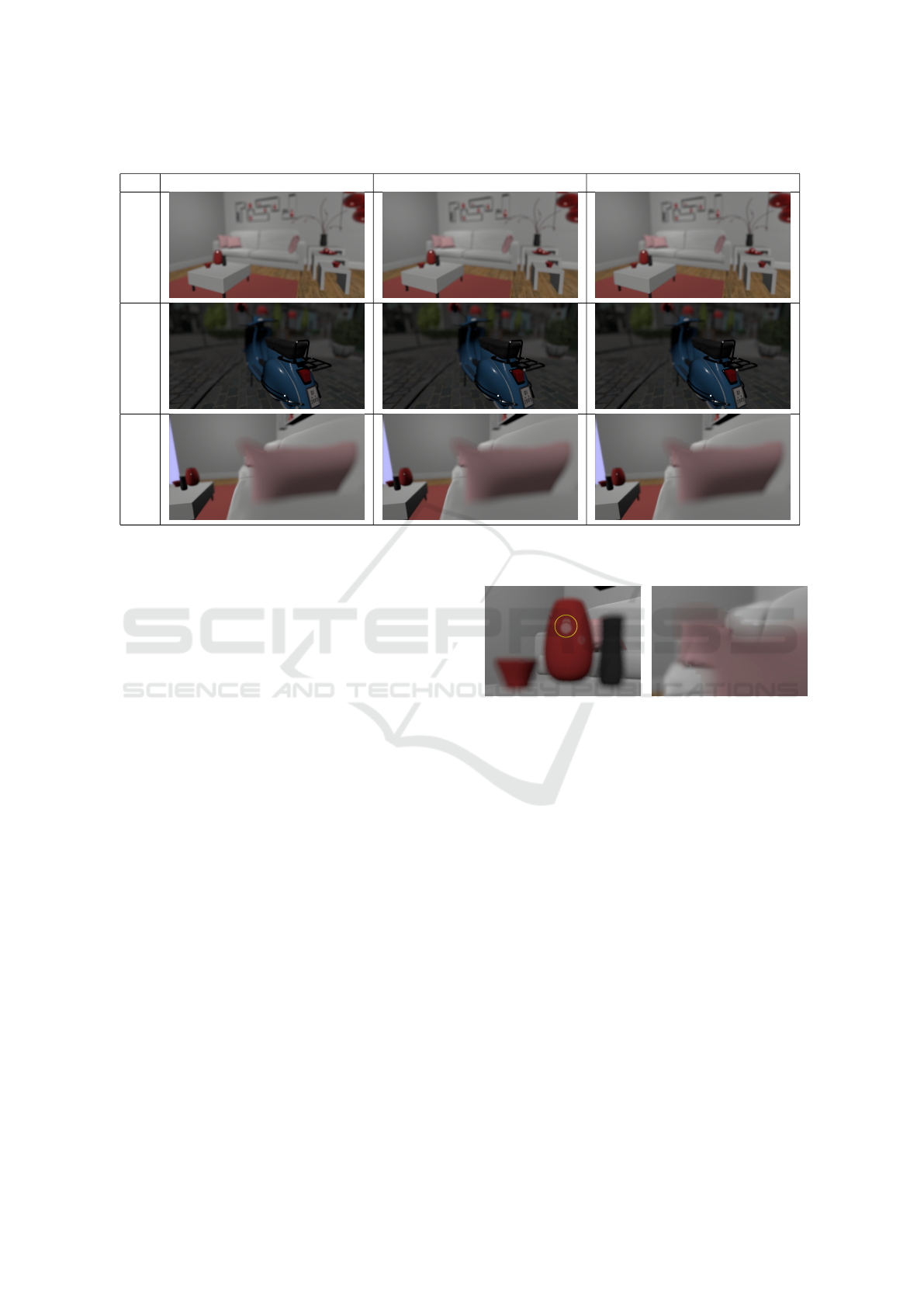
Table 1: Shots used for profiling.
m 1 30 50
BG
M
FG
wide shot and a foreground-dominant (FG) close-up
of PINK ROOM, as well as a mixed (M) medium shot
of BISTRO EXTERIOR with different m as shown in
Table 1, with their performances in Table 2. In partic-
ular, the ray trace pass duration is calculated from the
combined GPU timings of the Direct3D API calls for
building acceleration structures and dispatching rays.
It can be noted that post-processing performances
are on par with implementations in a production en-
gine. As a reference, Unreal Engine achieves 1.59
ms on a GTX 1080 (Abadie, 2018). While the dura-
tion of other passes remains relatively constant, the
cost of the ray trace pass increases with additional
rays shot per pixel except for BG. This is because
background geometry is predominantly rendered with
post-processing, which means that few rays are traced
at all. For M, part of the moped is in the foreground
and is ray-traced, while the cushion and parts of the
sofa are completely ray-traced for FG. Hence, an in-
creasing m gives a dip in frame rate for FG but not M.
The cost of 1 ray for M and FG are 0.04 ms and 0.07
ms respectively. These observations allow us to de-
sign content-based adaptive trade-offs between qual-
ity and performance, which we defer to future work.
5.3 Limitations and Future Work
Although our technique improves the quality of semi-
transparencies at the silhouettes of blurry foreground
geometry, we acknowledge that it currently might not
fare as well as other more efficient state-of-the-art
post-processing approaches in the following aspects.
We hope to continue working on performance opti-
mizations alongside visual enhancements.
(a) Ghosting (b) Tiling
Figure 8: Artifacts.
Ghosting artifacts currently appear from temporal
accumulation as shown in Figure 8a. Using colour-
based neighbourhood clamping to combat ghosting as
explained in Karis (2013) reintroduces noise as noted
in Schied et al. (2017). While we have reduced the
blend factor during motion, ghosting is still not elim-
inated especially at low frame rates as it takes longer
for temporal accumulation to converge to the new
colour. Potentially, we could adopt ideas from Schied
et al. (2018) which manages to eliminate ghosting ar-
tifacts by estimating per-pixel blend factors.
Due to our insufficiently-sized ray mask, tiling ar-
tifacts are also observed when foreground objects are
too close to the camera as seen in Figure 8. Ideally,
our ray mask should be scaled based on CoC size to
account for the sizeable blur of objects close to the
camera. Hence, for our technique, we could scale our
ray mask by the maximum CoC in the neighbourhood.
With 1 sample per pixel, noise generated is inher-
ently difficult to remove. Adopting a final blur like
A Hybrid System for Real-time Rendering of Depth of Field Effect in Games
87

Table 2: Pass durations (in ms) and frame rates.
Shot m 1 30 50
BG 1.70 1.72 1.70
M 2.07 2.05 2.04
Rasterization
FG 1.90 1.89 1.89
BG 1.43 1.44 1.42
M 1.63 1.62 1.69
Post-Process
FG 1.68 1.67 1.66
BG 0.64 0.64 0.65
M 0.66 0.66 0.66
G-Buffer & σ
2
Blur
FG 0.65 0.65 0.64
BG 0.18 0.19 0.18
M 0.26 1.36 2.08
Ray Trace
FG 0.40 2.08 3.25
BG 0.60 0.60 0.60
M 0.60 0.60 0.60
Accumulation
FG 0.61 0.61 0.61
BG 0.35 0.34 0.34
M 0.33 0.34 0.34
Median
FG 0.34 0.34 0.34
BG 0.42 0.42 0.42
M 0.81 0.79 0.81
Recon-Composite
FG 1.42 1.40 1.42
BG 0.53 0.53 0.53
M 0.53 0.53 0.53
Final TAA
FG 0.53 0.53 0.53
BG 0.64 0.64 0.66
M 0.64 0.61 0.65
Others
FG 0.64 0.62 0.65
BG 2.19 2.19 2.19
M 2.66 3.75 4.49
Our Pass
FG 3.42 5.08 6.26
BG 6.49 6.52 6.50
M 7.53 8.56 9.40
Total Duration
FG 8.17 9.79 10.99
BG 181 179 180
M 96 97 97
Frame Rate
FG 146 122 110
Barr
´
e-Brisebois et al. (2019) for reflections resulted
in a loss of detail in semi-transparent areas. However,
considering that we only ray trace within a ray mask,
using a variable number of rays is a good compromise
for better image quality.
As many post-process effects remain to be en-
hanced with ray tracing, we are also exploring hybrid
rendering for motion blur. Post-processed motion blur
poses similar issues of semi-transparencies. Hence,
we are also investigating the use of ray tracing to
uncover true background information behind motion-
blurred foreground objects (Tan et al. (2020b)).
6 CONCLUSION
We present a hybrid real-time rendering technique for
the DoF effect in games. Our ray trace pass attains
better image quality by rendering more accurate semi-
transparencies with minimal artist overhead. Addi-
tionally, our ray mask and adaptive ray count, even
when unoptimized, allow us to achieve relatively in-
teractive frame rates. In future, we hope to augment
and incorporate other effects like motion blur into our
hybrid real-time rendering pipeline. Our hybrid ren-
dering engine will be open-sourced for the benefit of
the research community and the industry.
ACKNOWLEDGEMENTS
We thank Wyman (2018) for the Falcor scene file
of THE MODERN LIVING ROOM (CC BY) as well
as the NVIDIA ORCA for that of UE4 SUN TEM-
PLE (CC BY-NC-SA) and AMAZON LUMBERYARD
BISTRO (CC BY). This work is supported by the
Singapore Ministry of Education Academic Research
grant T1 251RES1812, “Dynamic Hybrid Real-time
Rendering with Hardware Accelerated Ray-tracing
and Rasterization for Interactive Applications”.
REFERENCES
Abadie, G. (2018). Advances in real-time rendering in
games: A life of a bokeh. In ACM SIGGRAPH 2018
Courses, SIGGRAPH ’18, New York, NY, USA. As-
sociation for Computing Machinery.
Akenine-M
¨
oller, T., Munkberg, J., and Hasselgren, J.
(2007). Stochastic rasterization using time-continuous
triangles. In Proceedings of the 22nd ACM SIG-
GRAPH/EUROGRAPHICS Symposium on Graphics
Hardware, GH ’07, pages 7–16, Goslar, DEU. Euro-
graphics Association.
Amazon Lumberyard (2017). Amazon lumberyard bistro,
open research content archive (orca).
Andrade, P., Sabino, T. L., and Clua, E. (2014). Towards a
heuristic based real time hybrid rendering - a strategy
to improve real time rendering quality using heuristics
and ray tracing. In 2014 International Conference on
Computer Vision Theory and Applications (VISAPP),
volume 3, pages 12–21.
Barr
´
e-Brisebois, C., Hal
´
en, H., Wihlidal, G., Lauritzen,
A., Bekkers, J., Stachowiak, T., and Andersson, J.
(2019). Hybrid rendering for real-time ray tracing. In
Haines, E. and Akenine-M
¨
oller, T., editors, Ray Trac-
ing Gems, chapter 25. Apress. http://raytracinggems.
com.
Beck, S., Bernstein, A. C., Danch, D., and Fr
¨
ohlich, B.
(1981). Cpu-gpu hybrid real time ray tracing frame-
GRAPP 2022 - 17th International Conference on Computer Graphics Theory and Applications
88

work. volume 0, pages 1–8. The Eurographics Asso-
ciation and Blackwell Publishing Ltd.
Belcour, L., Soler, C., Subr, K., Holzschuch, N., and Du-
rand, F. (2013). 5d covariance tracing for efficient de-
focus and motion blur. ACM Trans. Graph., 32(3).
Benty, N., Yao, K.-H., Clarberg, P., Chen, L., Kallweit,
S., Foley, T., Oakes, M., Lavelle, C., and Wyman, C.
(2020). The Falcor rendering framework.
Bukowski, M., Hennessy, P., Osman, B., and McGuire, M.
(2013). The Skylanders SWAP Force depth-of-field
shader. In GPU Pro 4: Advanced Rendering Tech-
niques, pages 175–184.
Cabeleira, J. P. G. (2010). Combining rasterization and ray
tracing techniques to approximate global illumination
in real-time. Master’s thesis, Portugal.
Canny, J. (1986). A computational approach to edge de-
tection. IEEE Trans. Pattern Anal. Mach. Intell.,
8(6):679–698.
Catmull, E. (1984). An analytic visible surface algorithm
for independent pixel processing. SIGGRAPH Com-
put. Graph., 18(3):109–115.
Chalmers, A., Debattista, K., and dos Santos, L. P. (2006).
Selective rendering: Computing only what you see.
In Proceedings of the 4th International Conference
on Computer Graphics and Interactive Techniques
in Australasia and Southeast Asia, GRAPHITE ’06,
pages 9–18, New York, NY, USA. ACM.
Chen, C.-C. and Liu, D. S.-M. (2007). Use of hardware
z-buffered rasterization to accelerate ray tracing. In
Proceedings of the 2007 ACM Symposium on Applied
Computing, SAC ’07, pages 1046–1050, New York,
NY, USA. ACM.
Cook, R. L., Porter, T., and Carpenter, L. (1984). Dis-
tributed ray tracing. SIGGRAPH Comput. Graph.,
18(3):137–145.
Dayal, A., Woolley, C., Watson, B., and Luebke, D. (2005).
Adaptive frameless rendering. In ACM SIGGRAPH
2005 Courses, SIGGRAPH ’05, New York, NY, USA.
ACM.
Demers, J. (2004). Depth of field: A survey of techniques.
In GPU Gems, chapter 23. Pearson Higher Education.
Epic Games (2017). Unreal engine sun temple, open re-
search content archive (orca).
Fatahalian, K., Luong, E., Boulos, S., Akeley, K., Mark,
W. R., and Hanrahan, P. (2009). Data-parallel ras-
terization of micropolygons with defocus and motion
blur. In Proceedings of the Conference on High Per-
formance Graphics 2009, HPG ’09, page 59–68, New
York, NY, USA. Association for Computing Machin-
ery.
Franke, L., Hofmann, N., Stamminger, M., and Selgrad, K.
(2018). Multi-layer depth of field rendering with tiled
splatting. Proc. ACM Comput. Graph. Interact. Tech.,
1(1).
Garcia, K. (2017). Circular separable convolution depth of
field. In ACM SIGGRAPH 2017 Talks, SIGGRAPH
’17, New York, NY, USA. Association for Computing
Machinery.
Hach, T., Steurer, J., Amruth, A., and Pappenheim, A.
(2015). Cinematic bokeh rendering for real scenes.
In Proceedings of the 12th European Conference on
Visual Media Production, CVMP ’15, New York, NY,
USA. Association for Computing Machinery.
Haeberli, P. and Akeley, K. (1990). The accumulation
buffer: Hardware support for high-quality rendering.
In Proceedings of the 17th Annual Conference on
Computer Graphics and Interactive Techniques, SIG-
GRAPH ’90, page 309–318, New York, NY, USA. As-
sociation for Computing Machinery.
Hertel, S., Hormann, K., and Westermann, R. (2009). A
hybrid gpu rendering pipeline for alias-free hard shad-
ows. In Ebert, D. and Kr
¨
uger, J., editors, Eurographics
2009 Areas Papers, pages 59–66, M
¨
unchen, Germany.
Hou, Q., Qin, H., Li, W., Guo, B., and Zhou, K. (2010). Mi-
cropolygon ray tracing with defocus and motion blur.
ACM Trans. Graph., 29(4).
Jimenez, J. (2014). Advances in real-time rendering in
games, part i: Next generation post processing in call
of duty: Advanced warfare.
Karis, B. (2013). Tone mapping.
Karis, B. (2014). High quality temporal supersampling.
Kraus, M. and Strengert, M. (2007). Depth-of-field render-
ing by pyramidal image processing. Comput. Graph.
Forum, 26:645–654.
Lauterbach, C. and Manocha, D. (2009). Fast hard and soft
shadow generation on complex models using selective
ray tracing. Technical report tr09-004, UNC CS.
Lee, S., Eisemann, E., and Seidel, H.-P. (2009). Depth-of-
field rendering with multiview synthesis. ACM Trans.
Graph., 28(5):1–6.
Lee, S., Kim, G., and Choi, S. (2008). Real-time depth-of-
field rendering using point splatting on per-pixel lay-
ers. Comput. Graph. Forum, 27:1955–1962.
Lehtinen, J., Aila, T., Chen, J., Laine, S., and Durand,
F. (2011). Temporal light field reconstruction for
rendering distribution effects. ACM Trans. Graph.,
30(4):55:1–55:12.
Lei, K. and Hughes, J. F. (2013). Approximate depth of field
effects using few samples per pixel. In Proceedings of
the ACM SIGGRAPH Symposium on Interactive 3D
Graphics and Games, I3D ’13, page 119–128, New
York, NY, USA. Association for Computing Machin-
ery.
Leimk
¨
uhler, T., Seidel, H.-P., and Ritschel, T. (2018).
Laplacian kernel splatting for efficient depth-of-field
and motion blur synthesis or reconstruction. ACM
Trans. Graph., 37(4).
Macedo, D. V. D., Serpa, Y. R., and Rodrigues, M. A. F.
(2018). Fast and realistic reflections using screen
space and gpu ray tracing—a case study on rigid and
deformable body simulations. Comput. Entertain.,
16(4).
Marrs, A., Spjut, J., Gruen, H., Sathe, R., and McGuire, M.
(2018). Adaptive temporal antialiasing. In Proceed-
ings of the Conference on High-Performance Graph-
ics, HPG ’18, pages 1:1–1:4, New York, NY, USA.
ACM.
McGraw, T. (2015). Fast bokeh effects using low-rank lin-
ear filters. Vis. Comput., 31(5):601–611.
A Hybrid System for Real-time Rendering of Depth of Field Effect in Games
89

McIntosh, L., Riecke, B. E., and DiPaola, S. (2012). Effi-
ciently simulating the bokeh of polygonal apertures in
a post-process depth of field shader. Comput. Graph.
Forum, 31(6):1810–1822.
Mehta, S. U., Yao, J., Ramamoorthi, R., and Durand, F.
(2014). Factored axis-aligned filtering for rendering
multiple distribution effects. ACM Trans. Graph.,
33(4).
Potmesil, M. and Chakravarty, I. (1982). Synthetic im-
age generation with a lens and aperture camera model.
ACM Trans. Graph., 1(2):85–108.
Rosado, G. (2008). Chapter 27. motion blur as a post-
processing effect. In Nguyen, H., editor, GPU Gems
3, chapter 27.
Sattlecker, M. and Steinberger, M. (2015). Reyes rendering
on the gpu. In Proceedings of the 31st Spring Confer-
ence on Computer Graphics, SCCG ’15, page 31–38,
New York, NY, USA. Association for Computing Ma-
chinery.
Schied, C., Kaplanyan, A., Wyman, C., Patney, A., Chai-
tanya, C. R. A., Burgess, J., Liu, S., Dachsbacher,
C., Lefohn, A., and Salvi, M. (2017). Spatiotempo-
ral variance-guided filtering: Real-time reconstruction
for path-traced global illumination. In Proceedings
of High Performance Graphics, HPG ’17, pages 2:1–
2:12, New York, NY, USA. ACM.
Schied, C., Peters, C., and Dachsbacher, C. (2018). Gra-
dient estimation for real-time adaptive temporal filter-
ing. Proc. ACM Comput. Graph. Interact. Tech., 1(2).
Selgrad, K., Reintges, C., Penk, D., Wagner, P., and Stam-
minger, M. (2015). Real-time depth of field using
multi-layer filtering. In Proceedings of the 19th Sym-
posium on Interactive 3D Graphics and Games, i3D
’15, page 121–127, New York, NY, USA. Association
for Computing Machinery.
Shirley, P., Aila, T., Cohen, J., Enderton, E., Laine, S., Lue-
bke, D., and McGuire, M. (2011). A local image re-
construction algorithm for stochastic rendering. In
Symposium on Interactive 3D Graphics and Games,
I3D ’11, page 9–14, New York, NY, USA. Associa-
tion for Computing Machinery.
Smith, J. L. (1996). Implementing median filters in xc4000e
fpgas. Xcell, 23(1).
Sousa, T. A. (2013). Advances in real-time rendering in
games, part ii: Graphics gems from cryengine 3.
Tan, Y. W., Chua, N., Biette, N., and Bhojan, A. (2020a).
Hybrid dof: Ray-traced and post-processed hybrid
depth of field effect for real-time rendering. In ACM
SIGGRAPH 2020 Posters, SIGGRAPH ’20, New
York, NY, USA. Association for Computing Machin-
ery.
Tan, Y. W., Xiaohan, C., and Bhojan, A. (2020b). Hybrid
mblur: Using ray tracing to solve the partial occlusion
artifacts in real-time rendering of motion blur effect.
In ACM SIGGRAPH 2020 Posters, SIGGRAPH ’20,
New York, NY, USA. Association for Computing Ma-
chinery.
Vaidyanathan, K., Munkberg, J., Clarberg, P., and Salvi, M.
(2015). Layered light field reconstruction for defocus
blur. ACM Trans. Graph., 34(2).
Valient, M. (2013). Killzone shadow fall.
Weier, M., Roth, T., Hinkenjann, A., and Slusallek, P.
(2018). Foveated depth-of-field filtering in head-
mounted displays. ACM Trans. Appl. Percept., 15(4).
Whitted, T. (1979). An improved illumination model
for shaded display. SIGGRAPH Comput. Graph.,
13(2):14–.
Wig42 (2014). The modern living room.
Wyman, C. (2018). Introduction to directx raytracing. In
ACM SIGGRAPH 2018 Courses, SIGGRAPH ’18.
Yan, L.-Q., Mehta, S. U., Ramamoorthi, R., and Durand, F.
(2016). Fast 4d sheared filtering for interactive render-
ing of distribution effects. ACM Trans. Graph., 35(1).
Zhang, X., Matzen, K., Nguyen, V., Yao, D., Zhang, Y., and
Ng, R. (2019). Synthetic defocus and look-ahead aut-
ofocus for casual videography. ACM Trans. Graph.,
38(4).
GRAPP 2022 - 17th International Conference on Computer Graphics Theory and Applications
90
