
Animating and Adjusting 3D Orthodontic Treatment Objectives
Maxime Chapuis
1,2 a
, Mathieu Lafourcade
1 b
, William Puech
1 c
, G
´
erard Guillerm
2
and Noura Faraj
1 d
1
LIRMM, Universit
´
e de Montpellier, CNRS, Montpellier, France
2
Groupe Orqual, Pau, France
Keywords:
Interactive System, 3D Models, Animation, Scripting.
Abstract:
In this paper, we present an interactive system to adjust and animate 3D orthodontic treatment objectives, the
main goal is to improve the communication tools used by orthodontists to exchange with their patients. Given
a 3D pathological patient model and a treatment objective, we propose to automatically generate intermedi-
ate steps using script-like treatment scenarios. The intermediate steps can then be adjusted using intuitive
manipulators, and used to produce an animation of the treatment. The resulting animation is a useful tool
to help patients visualize the potential evolution of their dentition and accept the treatment. The proposed
system relies on the registration of a reference model on both the treatment objective and the patient-specific
3D segmented mesh, to automatically position key feature points and create control curves. These primitives
are used to both, guide teeth movements during the animation, and provide manipulators to allow for user
interactions. The key contributions of this work are (a) the use of a registered reference model to position and
create intuitive control primitives, and (b) the introduction of script-like treatment scenarios to facilitate and
minimize user interactions during the creation of intermediate treatment steps.
1 INTRODUCTION
Computer aided orthodontic treatment planning is
now the standard way of designing a treatment as it
improves its outcome and allows for a 3D preview of
the patient’s dentition with the desired alignment and
occlusion. This preview, called a treatment objective,
is also a communication tool between the practitioner
and the patient. By viewing the expected outcome,
patients are able to better understand the proposed
treatment, and are more likely to adhere to it. To take
it a step further, an animation of the treatment can be
proposed to illustrate the different states of their den-
tition at different stages of the treatment. However,
doing a simple interpolation between the initial state
and the objective is not correct, as it does not reflect
the different steps of a treatment. Indeed, to be use-
ful, a treatment animation should include intermedi-
ate steps. The question is then, how to define them?
One way to do it, is to manually place each tooth in
the desired position at each step. However, this so-
a
https://orcid.org/0000-0003-0876-8711
b
https://orcid.org/0000-0003-2832-2143
c
https://orcid.org/0000-0001-9383-2401
d
https://orcid.org/0000-0001-6637-0336
lution is a tedious time consuming process. To ad-
dress this issue, we propose to use a set of instructions
(called actions) to allow the user to define a treatment
scenario, and automatically generate the intermediate
steps. A scenario contains the collection of actions
for each step of the treatment. Theses actions (similar
to a scripting language) reflect the intention of the or-
thodontist during the treatment (extract, level, align,
rotate, etc.). In this paper, we propose a method that
can take any 3D treatment objective as an input, and
allows to easily create an animation of the treatment
with clearly defined intermediate steps. To guide the
movements during the animation, our method relies
on a set a parametric curves automatically positioned
on the input models, which can be modified through
the use of control points. Manipulators are also pro-
vided in the case the user wants to adjust the generated
intermediate steps or the treatment objective.
The rest of the paper is organized as follows. First
we present related work in Section 2. Then, our pro-
posed method is detailed in Section 3. The results
of our method applied to real patient models are pre-
sented and discussed in Section 4. Finally, in Sec-
tion 5 we conclude and present future work.
60
Chapuis, M., Lafourcade, M., Puech, W., Guillerm, G. and Faraj, N.
Animating and Adjusting 3D Orthodontic Treatment Objectives.
DOI: 10.5220/0010822100003124
In Proceedings of the 17th International Joint Conference on Computer Vision, Imaging and Computer Graphics Theory and Applications (VISIGRAPP 2022) - Volume 1: GRAPP, pages
60-67
ISBN: 978-989-758-555-5; ISSN: 2184-4321
Copyright
c
2022 by SCITEPRESS – Science and Technology Publications, Lda. All rights reserved

Figure 1: Overview of the system.
2 RELATED WORK
Automatic tooth arrangement is the task of predict-
ing a proper tooth arrangement given a pathological
dental model (i.e a plausible result of the orthodon-
tic treatment). Different types of methods have been
developed for such a task. Kumar et al. proposed a
simulation-based approach, minimizing the energy of
a spring-mass system, where the springs represent or-
thodontic constraints (Kumar et al., 2013b). Cheng
et al. based their approach on satisfying geomet-
ric constraints, by positing feature points on different
planes and curves (Cheng et al., 2015). More recently,
Wei et al. and Li et al. proposed two deep-learning
based methods for automatic tooth arrangement (Wei
et al., 2020; Li et al., 2020a). Deep-learning based
methods offer good-quality tooth alignment on com-
mon cases, but require large data-sets of pre- and post-
treatment orthodontic cases.
When producing a treatment animation, the goal
is, given an initial and a target arrangement, to show
the evolution of the dentition over time. When the
two arrangements are close, using a simple interpola-
tion to compute the intermediate states is reasonable.
In the context of invisible appliances, Li et al. use a
more elaborate strategy. They formulate the problem
as a path planning problem (Li et al., 2020b). The
objective is to find, for each tooth, a path going from
the initial situation to the target, while minimizing the
translation distance, the rotation angle, and avoiding
collisions with surrounding teeth. To solve this opti-
mization problem, they first initialize the solution us-
ing the interpolated values, and then refine it using an
artificial bee colony algorithm. Another paper, by Li
et al., suggests that genetic algorithms can be used to
find proper paths, but the authors only present partial
results, and it is unclear how the teeth transformations
are coded in their method (Li et al., 2009).
3 PROPOSED METHOD
Given a 3D visual treatment objective, we propose
a method allowing for the automatic creation of in-
termediate treatment steps using a script-like sce-
nario. We also provide manipulators, allowing for
three levels of user interactions, to adjust the gener-
ated steps and the treatment objective. During the
generation process and the interactions, teeth move-
ments are guided by a set of control points and para-
metric curves automatically positioned on the input
models. To achieve this our method relies on the reg-
istration of a reference model onto the input arrange-
ments. The registration data allows us to transfer the
control points of the reference model on the input
models. The whole process is illustrated in Fig. 1.
In Section 3.1 and Section 3.2, we first detail the
registration process and the curves setup. Then in
Section 3.3 we detail the different manipulators, and
finally we present the process for creating the ani-
mation with a user-defined treatment scenario in Sec-
tion 3.4.
3.1 Registration Process
The goal of the registration process, is to automati-
cally position key control points on both the patho-
logical arrangement and the target arrangement. This
process is applied on each input model independently.
The reference model R, shown on Fig. 2a, is a
generic adult dentition with its teeth in a standard
configuration, and control points placed at the center
of the teeth vestibular faces, in the fashion of braces
(Fig. 2b). The vestibular side of a tooth faces the lips
and cheeks. Here, the use of a registered reference
model gives the ability to transfer properties from the
reference model to the input models, and to recon-
struct potential missing information (such as occluded
mesh parts or roots). Each control point has a refer-
ence frame computed using the up vector and the vec-
tor tangent to the arch at the point position. These
reference frames are used to define the reference ori-
Animating and Adjusting 3D Orthodontic Treatment Objectives
61
entations of the teeth. Throughout the registration and
the interactions, the control points are subject to the
same transformations as to their corresponding tooth.
The registration process is composed of two steps,
a rigid registration (Section 3.1.1), and a non-rigid
registration (Section 3.1.2).
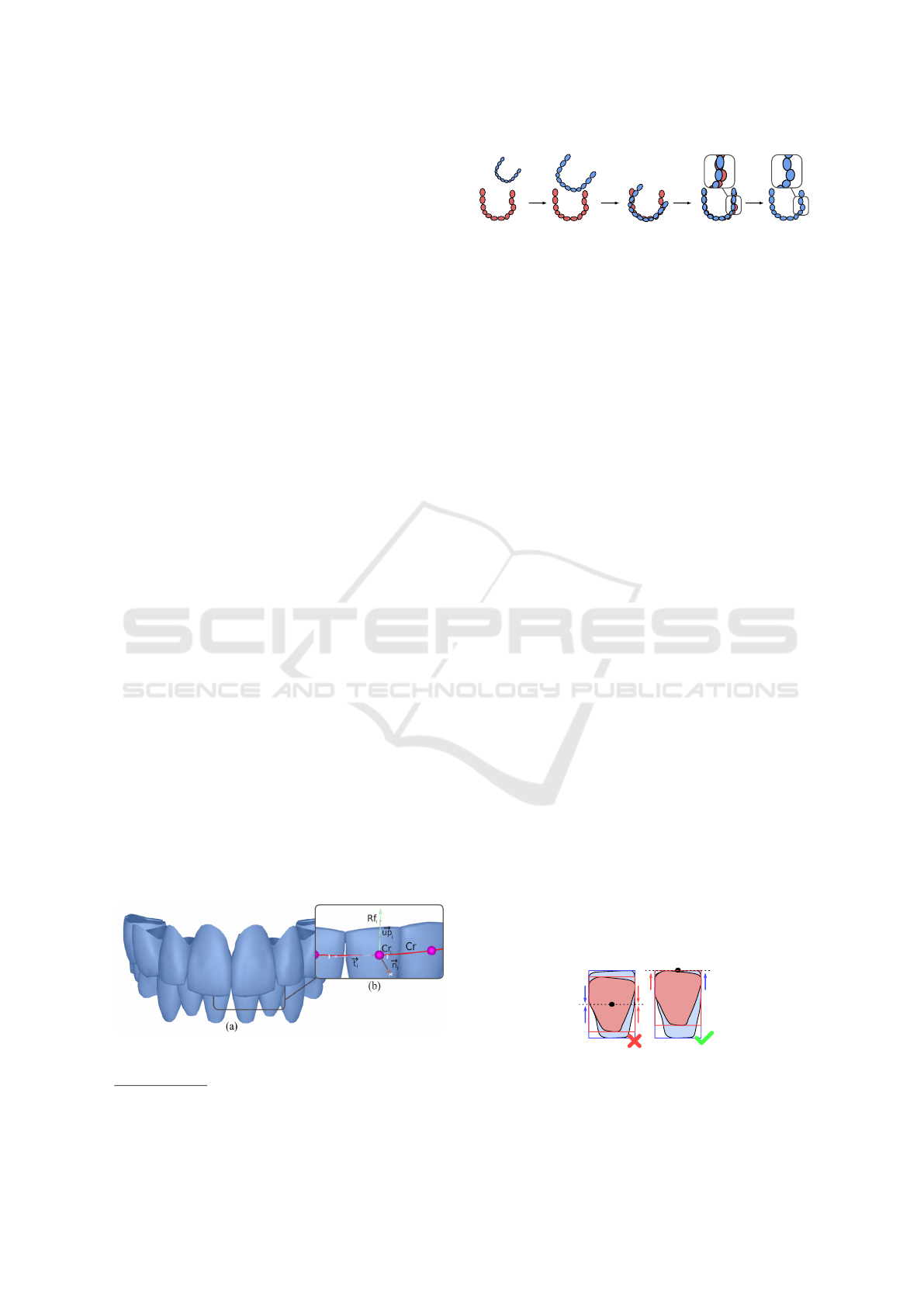
3.1.1 Rigid Registration
The main algorithm used to carry out the rigid regis-
tration is the Iterative Closest Point (ICP) (Besl and
McKay, 1992; Chen and Medioni, 1992). This al-
gorithm iteratively constructs a rigid transformation
which minimizes the difference between two point-
clouds by finding point correspondences in the two
data-sets. As the ICP algorithm is sensitive to the ini-
tial alignment, the rigid registration (Fig. 3) starts by
an initialization step. Its purpose is to place the ref-
erence model R in a good enough starting position to
perform an ICP on each tooth. This initialization is
done by scaling and centering R on the input model
P (Fig. 3b and Fig. 3c). These operations are done
“model-wise”, meaning that every tooth is scaled by
the same ratio and translated by the same vector. The
scaling ratio is estimated by averaging the ratios be-
tween the incisors of P and R. The incisors are well
suited for this purpose as they are almost always en-
tirely visible in patient models. The two models are
then roughly aligned by a model-wise ICP (Fig. 3d).
Then “tooth-wise” operations are performed: each
tooth of R is scaled to match its corresponding tooth in
P. To end the initialization process, the teeth bound-
ing boxes P and R are aligned. Mandibular bounding
boxes
1
are aligned on their upper center, and max-
illary bounding boxes
2
on their lower center. The
choice to align the top of the crowns is motivated
by the fact that patient teeth are not always entirely
visible. Therefore, centering them on their bounding
boxes centers would result in a poor initialization for
the ICP (Fig. 4).
Finally, each tooth in R is registered to the cor-
responding tooth in P by a tooth-wise ICP (Fig. 3e).
Figure 2: a. Front view of our reference model, b. Control
points are placed at the center of the teeth vestibular faces.
1
Mandibular refers to the lower arch.
2
Maxillary refers to the upper arch.
(a)
(b) (c) (d)
(e)
Figure 3: Reference model rigid registration (blue) on the
patient model (red): a. Initial alignment, b. Uniform scal-
ing, c. Centering, d. Model-wise ICP, e. Tooth-wise scal-
ing, centering and ICP.
Only the vertices contained in the bounding boxes of
the patient’s teeth are considered during the ICP. The
result of the rigid registration is a modified version of
R called P
0
, with the same tooth arrangement as the
patient.
3.1.2 Non-rigid Registration
The teeth of the reference model are generic teeth
and thus, do not match the patients teeth geometry.
These differences are mitigated by projecting the ref-
erence crowns vertices onto the patient’s crowns using
the projection method APSS (Guennebaud and Gross,
2007). To avoid unwanted deformations, care should
be taken to only project overlapping vertices. The re-
sult of this final registration step is shown on Fig. 5a
and Fig. 5b.
3.2 Curves Setup
On each arch, two curves are created, the reference
curve Cr, and the arch curve Ca. The former is used to
translate and orient teeth along the arch, and the latter
to adjust the shape of the arch with the appropriate
manipulator (Section 3.3.3).
3.2.1 Reference Curve and Patient Curve
The control points of the teeth of the reference model
R are used as the control points of a parametric curve
Cr(t), called the reference curve. This reference curve
is a Catmull–Rom spline (Catmull and Rom, 1974).
The choice to use a Catmull–Rom spline is moti-
vated by its interpolating properties (the curve goes
exactly through the control points), and its relatively
low computational cost. This curve gives the ability
Figure 4: a. The bounding boxes of a mandibular reference
tooth (blue) is centered on the bounding box of its corre-
sponding patient tooth (red), b. The same teeth are aligned
on the upper center of their bounding boxes.
GRAPP 2022 - 17th International Conference on Computer Graphics Theory and Applications
62

P
(a) (b)
P'
Tooth-wise ICP
APSS
Projection
Figure 5: a. Views of the lower arches of the patient model
P (red) and the fully registered reference model P
0
(blue),
b. Comparison of the right lower first molar before APSS
(top) and after (bottom).
to define a reference position and orientation at any
parameter t. It also has the benefit of being an in-
tuitive primitive for orthodontists, as it resembles an
orthodontic wire with braces. The orientation used for
each control point corresponds to its initial reference
frame multiplied by the rotation part of the transfor-
mation computed during the registration.
The patient curve Cp is constructed in a similar
way using the control points of the registered refer-
ence P
0
. The positions and orientations along Cp re-
flect the dental disorders of the patient.
3.2.2 Arch Curve
Following the method proposed by Kumar et al. (Ku-
mar et al., 2013a), cusps and incisal edges are com-
puted on the treatment objective (R). Theses features
are then transferred to the pathological model (P
0
) us-
ing the previously computed registration transforma-
tions. Since we transfer the feature points, we en-
sure that they are the same on both models. Their re-
spective arch forms can then be derived as the curves
passing through the distobuccal cusps of the first mo-
lars, the canines cusps and the midpoint of the incisors
of each arch as illustrated on Fig. 6. The arch forms
are represented by Catmull–Rom splines made of five
control points each (blue spheres on Fig. 6).
3.3 Manipulators
The manipulators available allow the users to express
their domain expertise by adjusting the treatment ob-
jective and the generated intermediate steps. To make
sure they were relevant to the domain, the different
manipulators were developed in collaboration with an
orthodontist. We propose several manipulators, of in-
creasing sophistication, permitting the adjustment at
different levels: individual teeth, groups of teeth, or
arch-forms. The usage of the different manipulators
is demonstrated in the companion video.
3.3.1 Teeth Manipulators
The simplest manipulator allows to freely translate
and rotate the individual teeth around their local axes.
The local axes of a given tooth are deduced using
the local frame of its corresponding control point. If
needed, this frame can be adjusted with the dedicated
manipulator. The selection of multiple teeth is possi-
ble, and allows the user to apply a translation to every
teeth of the selection. Note that there is a dedicated
manipulator to level a group of selected teeth. This
has the action of setting every control point of the se-
lection to the same level on the vertical axis (based on
the vertical position of the first tooth of the selection).
Finally, the extraction manipulator removes a tooth
from the arrangement. Tooth extraction is a typical
way to make room when the teeth are too cluttered to
be aligned properly.
3.3.2 Space Corrections
The spaces manipulator can be used to close inter-
dental spaces on a given range of teeth. This action
is done by moving each ill-positioned tooth along the
reference curve Cr, going from the incisors to the mo-
lars. The induced collisions are resolved along the
way, as if the moving tooth was pushing its neighbors,
as illustrated on Fig. 7.
When included in the range, the pair of central in-
cisors have to be treated first then, the left and right
side can be processed independently.
3.3.3 Arch Form Deformation
Each arch form is represented by a Catmull–Rom
spline made of five control points Ca. The arch defor-
mation manipulator allows, by moving one of point
of Ca, to move every teeth accordingly (every control
point of Cr). The procedure is the following. When
an arch point is moved, the arch curve Ca is modified
(slightly) and produces Ca
0
. To propagate this mod-
ification to the teeth, we compute the translation to
apply to each control point Cr
i
as the difference in po-
sition between Ca
0
(t) and Ca(t) (where t is the curve
parameter corresponding to the projection of Cr
i
on
Ca). The teeth collisions induced by the translations
are resolved as described is Section 3.3.2. Once the
teeth are in their correct positions, their orientation
are adjusted to match the reference orientations of the
newly formed Cr (the reference orientations are com-
puted as described in Section 3.2 .)
Animating and Adjusting 3D Orthodontic Treatment Objectives
63
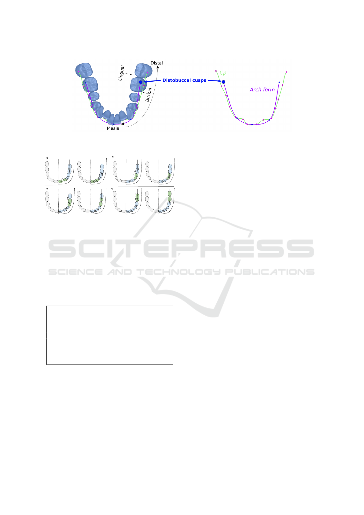
Figure 6: The main features extracted on the lower arch of P
0
. In green, Cp made of the registered control points. In purple,
the arch form going through the distobuccal cusps of the first molars, the canines cusps and the midpoint of the incisors.
Figure 7: The space between each ill-positioned pair
(green) is adjusted. The spaces can either be closed (a) or
opened to de-intersect teeth (b),(c),(d).
3.4 Animation
To create the intermediate treatment steps necessary
for the animation, our method relies on user-defined
treatment scripts.
3.4.1 Treatment Script
step :
ex t rac t l o we r f ir st p rem o lar s
ex t rac t u p pe r se c on d p r emo lar s
step :
lev e l te e th
step :
ali g n te e th
Listing 1: Example of treatment script defining
intermediate steps.
Given a target arrangement, and an initial pathologi-
cal one, the user defines for each step, the set of ac-
tions to execute in order to get to the objective. These
actions take the form of verbs, reflecting the intention
of the orthodontist, and can be applied to a particu-
lar tooth, a group of teeth, or every tooth of an arch.
An example of treatment script is shown in Listing 1.
In this example, three intermediate steps are defined.
The first one contains two extract actions, applied on
two groups of teeth (the lower first premolars and the
upper second premolars). Actions applied to a group
of teeth are applied to each tooth of the group. The
second step applies the action level on every tooth,
which has the effect of putting the teeth on the same
horizontal plane (based on what is defined in the ob-
jective). The third one, positions the teeth in their tar-
get position using the action align. There is a fourth
implicit step which is, getting to the objective.
3.4.2 Actions
The set of currently available actions is described in
Table 1. Every action is implemented using the con-
trol points or the curves computed in Section 3.2.
The process used to generate the steps is the fol-
lowing. Starting from the initial arrangement, every
time a new step is declared in the script with the step
action: copy the current arrangement and apply the
actions of the step. The application of an action de-
pends on its implementation. Most of the time, it is
done by computing the transformation difference be-
tween the current arrangement and the target arrange-
ment, and only applying a particular component of
the resulting transformation (the component relevant
to the action).
3.4.3 Arrangements Interpolation
The animation between two given dental arrange-
ments is done by linearly interpolating the positions
and orientations of the teeth. Let Pi
j
and Oi
j
be the
position and orientation of the tooth j in an initial ar-
rangement, and Pt
j
and Ot
j
be the position and orien-
tation of the tooth j in a target arrangement, then for a
given interpolation value t (with 0 6 t 6 1):
P
j
(t) = lerp(Pi
j
, Pt
j
, t)
O
j
(t) = slerp(Oi
j
, Ot
j
, t),
(1)
where the lerp function is the regular linear interpola-
tion and the slerp function is the quaternion spherical
GRAPP 2022 - 17th International Conference on Computer Graphics Theory and Applications
64

interpolation (Shoemake, 1985). Here, the slerp func-
tion is used to produce constant-speed rotations. Note
that we have a t value for the position t
p
and a sec-
ond one for the orientation t
o
. This gives the ability to
define different interpolation speeds for the position
and the orientation. Similarly to Li et al., we limit
the amount of rotation and translation possible for a
tooth during one animation step (2° of rotation, and
0.2mm of translation) (Li et al., 2020b). These em-
pirical values are here to represent the limits of the
alveolar bone reconstruction process.
Given every intermediate steps of a treatment, the
resulting animation is the interpolation between the
successive arrangements.
4 EXPERIMENTAL RESULTS
To illustrate our method, we show our pipeline ap-
plied to two representative patient cases, and compare
the resulting animation with the simple linear interpo-
lation between the initial and target arrangement.
Case A (the red model on Fig. 9) presents mod-
erate disorders. The main issues are its upper right
second premolar position (tooth 15), and its anterior
teeth inclination. The treatment scenario for this case
is: first level the teeth, then re-position tooth 15 and
finally align and rotate the remaining teeth. The an-
imation is illustrated on the maxilla in Fig. 9. The
objective is shown in blue, the produced intermediate
steps are in green. The top part of the figure shows
the linear interpolation for the same animation times
t
1
and t
2
(in grey), and the bottom part is our complete
animation.
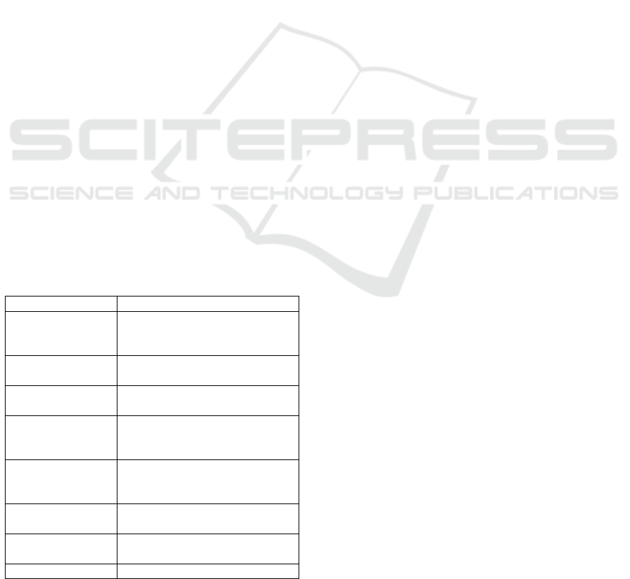
Case B (the red model on Fig. 10) illustrates a case
where the provided treatment objective needs to be
adjusted. This can happen when using an automatic
teeth arrangement method to generate the objective
(Section 2). These methods don’t usually predict teeth
extractions or arch expansion. The real treatment plan
for this case suggests the extraction of the premolar.
Therefore, as a preliminary step, the first premolars
are extracted and the anterior teeth are re-positioned
using the manipulators described in Section 3.3. The
edited objective is shown on Fig. 8. The treatment
script used to produce the animation is same as List-
ing 1. The resulting animation on the mandibula is
shown on Fig. 10.
The linear interpolation animation is shown in
grey for both cases at the top of Fig. 9 and Fig. 10.
Due to the fact that the interpolation corrects the ro-
tation and position of every teeth simultaneously, we
observe multiple differences. On case A, at t
1
, our an-
imation only straightens up the teeth to position them
on a same horizontal plane, whereas in the interpo-
lation animation, the teeth moved uniformly closer
to the objective. The difference is clear on tooth 15
(zoomed in). Similar differences are be observed on
case B. The companion video includes the animations
of both cases.
Figure 8: Adjustment of the initial treatment objective by
extracting the premolars, and re-positioning the anteriors.
5 CONCLUSION
In this paper, we present a method allowing to intu-
itively adjust a 3D treatment objective, and to gener-
ate intermediate treatment steps given a user-defined
treatment scenario. The resulting animation is a
more faithful representation of the intended treatment
hence is a better illustration than the simple interpo-
lation between the initial situation and objective, and
may improve the patient’s understanding of his treat-
ment.
In future work, we plan on providing arch-wire
actions to mimic the use of arch-wires of differ-
ent shapes (round, rectangular, squared) and stiffness
(low, medium, high). This requires the use of ad-
ditional patient data such as roots and surrounding
cranio-facial structures. One considered solution is
the registration of a dental cone beam computed to-
mography on our 3D model.
REFERENCES
Besl, P. J. and McKay, N. D. (1992). A method for regis-
tration of 3-d shapes. IEEE Transactions on Pattern
Analysis and Machine Intelligence, 14(2):239–256.
Catmull, E. and Rom, R. (1974). A class of local interpo-
lating splines. In BARNHILL, R. E. and RIESEN-
FELD, R. F., editors, Computer Aided Geometric De-
sign, pages 317–326. Academic Press.
Chen, Y. and Medioni, G. (1992). Object modelling by reg-
istration of multiple range images. Image and Vision
Computing, 10(3):145 – 155. Range Image Under-
standing.
Cheng, C., Cheng, X., Dai, N., Liu, Y., Fan, Q., Hou, Y.,
and Jiang, X. (2015). Personalized Orthodontic Accu-
rate Tooth Arrangement System with Complete Teeth
Model. Journal of Medical Systems, 39(9):84.
Animating and Adjusting 3D Orthodontic Treatment Objectives
65
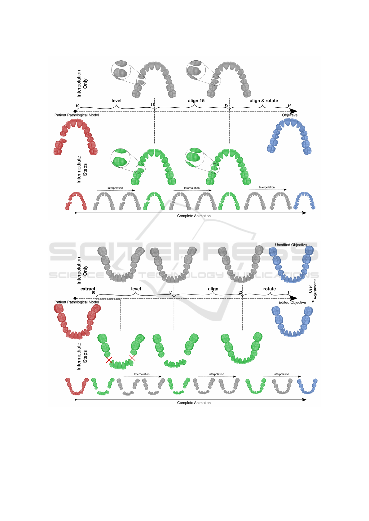
Figure 9: Animation for Case A: Given the initial pathological model (in red) and the objective (in blue), each step produces
an intermediate arrangement (in green). At the top, the linear interpolation in shown for the same animation times t
1
and t
2
.
Our complete animation is shown at the bottom.
Figure 10: Animation for Case B: Given the initial pathological model (in red) and the edited objective (in blue), each step
produces an intermediate arrangement (in green). The red crosses indicate the extraction of two premolars. At the top, the
linear interpolation between the initial situation and the unedited objective is shown. Our complete animation is shown at the
bottom.
GRAPP 2022 - 17th International Conference on Computer Graphics Theory and Applications
66
Guennebaud, G. and Gross, M. (2007). Algebraic point set
surfaces. ACM Trans. Graph., 26(3):23–es.
Kumar, Y., Janardan, R., and Larson, B. (2013a). Automatic
feature identification in dental meshes. Computer-
Aided Design and Applications, 9:747–769.
Kumar, Y., Janardan, R., and Larson, B. (2013b). Automatic
virtual alignment of dental arches in orthodontics.
Computer-Aided Design and Applications, 10:371–
398.
Li, X., Bi, L., Kim, J., Li, T., Li, P., Tian, Y., Sheng, B., and
Feng, D. (2020a). Malocclusion treatment planning
via pointnet based spatial transformation network. In
Martel, A. L., Abolmaesumi, P., Stoyanov, D., Ma-
teus, D., Zuluaga, M. A., Zhou, S. K., Racoceanu,
D., and Joskowicz, L., editors, Medical Image Com-
puting and Computer Assisted Intervention – MICCAI
2020, pages 105–114, Cham. Springer International
Publishing.
Li, Z., Li, K., and Li, B. (2009). Research on path plan-
ning for tooth movement based on genetic algorithms.
In 2009 International Conference on Artificial Intel-
ligence and Computational Intelligence, volume 1,
pages 421–424.
Li, Z., Liu, T., Li, H.-A., and Sun, Z. (2020b). Orthodon-
tic path planning method based on optimized artificial
bee colony algorithm. Journal of Physics: Conference
Series, 1544(1):012017.
Shoemake, K. (1985). Animating rotation with quaternion
curves. SIGGRAPH Comput. Graph., 19(3):245–254.
Wei, G., Cui, Z., Liu, Y., Chen, N., Chen, R., Li, G., and
Wang, W. (2020). TANet: Towards Fully Automatic
Tooth Arrangement. In Lecture Notes in Computer
Science (including subseries Lecture Notes in Artifi-
cial Intelligence and Lecture Notes in Bioinformatics),
volume 12360 LNCS, pages 481–497.
APPENDIX
Table 1: Currently available actions.
Action Effect
step Declare a new step, and initial-
ize it with the current configura-
tion.
extract Extract a tooth from the current
configuration.
level Position the teeth on the same
horizontal plane.
rotate Correct the orientation of a
tooth on its up axis (local y
axis).
incline Correct the orientation of a
tooth on its mesio-distal axis
(local z axis).
lock /unlock Prevent the tooth from moving
move.
align Position the teeth at their target
position on the arch.
close spaces Close inter-dental spaces.
Animating and Adjusting 3D Orthodontic Treatment Objectives
67
