
Use of Compiler Intermediate Representation for Reverse Engineering:
A Case Study for GCC Compiler and UML Activity Diagram
Rania Mzid
1,3 a
, Asma Charfi
2
and Najmeddine Etteyeb
1
1
ISI, University Tunis-El Manar, 2 Rue Abourraihan Al Bayrouni, Ariana, Tunisia
2
Universit
´
e Paris-Saclay, CEA, List, F-91120, Palaiseau, France
3
CES Lab ENIS, University of Sfax, B.P:w.3, Sfax, Tunisia
Keywords:
Model-driven Engineering, Reverse-engineering, Compiler Intermediate Representation, GCC, Gimple,
Control Flow Graph, UML Activity Diagram.
Abstract:
Nowadays systems are no longer made from scratch, they use existing third-party components or legacy soft-
ware. Providing methods/techniques to facilitate the comprehension of existing software is beneficial to in-
crease productivity, especially when dealing with their reuse and/or modernization. Model Driven Engineering
(MDE) offers a set of guidelines to manage the complexity of software systems during their development. In
that context, the reverse-engineering process aims to describe a source code at higher level of abstraction
using automatic transformations. This paper proposes an extensible MDE approach for behavioural reverse
engineering. The proposed approach aims to make the reverse transformation independent of the source pro-
gramming language. Starting from a given source code written in any programming language, the proposed
approach integrates an intermediate step based on compiler’s front-end to generate an intermediate represen-
tation. Then, it performs a model transformation to extract behavioural aspects from the source code and
generates a graph that describes its control flow. The different steps of the approach are automated. We apply
the approach to case study using GCC and GIMPLE as intermediate representation and UML activity diagram
as control flow graph to show its viability.
1 INTRODUCTION
Embedded systems are commonly used in many fields
such as automotive, avionics, telecommunications,
medical and consumer electronics. These applica-
tions are providing multiple sophisticated features
which are customized to meet the user’s needs di-
versity. As a result, the software development pro-
cess for the embedded systems may be both time and
effort consuming. Difficulties caused by the devel-
opment task were raised since the beginning of the
software crisis. Several projects have faced catas-
trophic failures due to over-budgets, over-time, prod-
uct non-conformity or even unachievable projects
(Glass, 2006) (Jørgensen and Moløkken-Østvold,
2006). Moreover, the exponential evolution of tech-
nologies, programming languages and platforms used
to develop such systems are making the development
task more and more challenging. Model Driven Engi-
neering (MDE) (Favre, 2004) (B
´
ezivin, 2005) (Atkin-
a
https://orcid.org/0000-0002-3086-370X
son and Kuhne, 2003) (Seidewitz, 2003) proposes so-
lutions to enhance the productivity during the devel-
opment process of software embedded systems. MDE
promotes a rise in level of abstraction, to manage the
increasing complexity, by introducing the use of mod-
els at the different development stages from the spec-
ification to the implementation.
MDE defines two main processes : forward engi-
neering and reverse engineering (Raibulet et al., 2017)
(Nelson, 2005). Forward engineering aims to gener-
ate executable code from high level descriptions of
the system. Reverse engineering can be defined as
the process of understanding software and producing
models describing it at a higher level of abstraction.
However, reverse engineering can be used in differ-
ent contexts. In (Martinez et al., 2013), four types of
reverse engineering are discussed. This classification
is based on the level of impact on the existing soft-
ware: (i) Re-documentation which involves the cre-
ation or revision of system documentation, (ii) Design
recovery which consists on creating a model or any
formal description of the system at a higher level of
Mzid, R., Charfi, A. and Etteyeb, N.
Use of Compiler Intermediate Representation for Reverse Engineering: A Case Study for GCC Compiler and UML Activity Diagram.
DOI: 10.5220/0010821700003119
In Proceedings of the 10th International Conference on Model-Driven Engineering and Software Development (MODELSWARD 2022), pages 211-218
ISBN: 978-989-758-550-0; ISSN: 2184-4348
Copyright
c
2022 by SCITEPRESS – Science and Technology Publications, Lda. All rights reserved
211

abstraction, (iii) Restructuring that is a lateral trans-
formation of the system within the same level of ab-
straction. Also maintains same level of functionality
and semantic and (iv) Re-engineering which involves
a combination of reverse engineering for comprehen-
sion, and a reapplication of forward engineering to
re-examine which functionalities need to be retained,
deleted or added.
The most common use of reverse engineering is
design recovery which aims to handle the complex-
ity of an existing source code throw model genera-
tion. Indeed, representing a source code at higher
level of abstraction have several advantages : (i) pro-
vides the various stakeholders with common point of
view to the project using human readable artefacts.
This could improve the coordination between them,
even if they have no technical experience, resulting
in a faster progress and a more robust software solu-
tion. (ii) allows running simulations on reverse engi-
neered models to test critical systems before deploy-
ing them (Lima et al., 2020) (Eshuis, 2006) (Banti
et al., 2011) (Ouchani et al., 2014) (iii) accelerates
program comprehension which in turn facilitate soft-
ware reuse and legacy software modernization (Mar-
tinez et al., 2013). The automation of models genera-
tion from source code could accelerate program com-
prehension and thus increase productivity during the
development of software systems. However, with the
wide variety of programming languages, enabling au-
tomatic transformation is very challenging. In fact,
for each considered programming language a set of
artefacts must be considered: (i) the meta-model of
the language, (ii) the transformation rules and (iii)
the meta-model of the target high level representation.
The definition of these artifacts requires a lot of efforts
and is time consuming.
To tackle this problem, we propose in this paper
a reverse engineering approach based on MDE prin-
ciples. This approach aims to reduce the effort and
the time required to perform the reverse engineering
transformation from source code to models when dif-
ferent programming languages are considered as in-
puts. The proposed approach defines two main steps
: 1) in the first step, we generate an intermediate rep-
resentation from the program code to be independent
from the source programming language, and 2) the
second step aims to produce high level models from
the intermediate representation. In this paper, we fo-
cus especially on behavioural models that describe at
high level the control flow in the code. The passage
between the steps are automatically done. The pro-
posed approach is generic and extensible to support
different source programming languages while main-
taining reasonable time to perform the reverse task.
The originality of this research is manifested by four
aspects :
• The proposed approach aims to extract be-
havioural aspects from an existing program code
and produce its control flow graph which could
facilitate program comprehension,
• The approach integrates an intermediate step
based on compiler intermediate representation in
order to make the reverse transformation indepen-
dent of the source programming language, which
may accelerate the reverse engineering process es-
pecially when dealing with existing software writ-
ten in different programming languages,
• We develop a tool which generates automatically
control flow graphs from a given source code.
The tool uses GCC front-ends and GIMPLE (Pop,
2006)(Merrill, 2003) as intermediate representa-
tion and generates Unified Modeling Language
(UML) activity diagrams (Cook et al., 2017),
• We apply the contribution to an IoT case study.
This paper is organized as follows. Section 2 dis-
cusses the related work. The proposed approach is
detailed in Section 3. In Section 4, we describe the
tooling support we provide. In Section 5, we apply
the proposed approach to a case study to show its ap-
plicability and section 6 concludes this paper and out-
lines some future directions.
2 RELATED WORK
The related work in this paper is twofold : (1) the
work dealing with the reverse engineering problem
and (2) the work combining compiler techniques and
model driven engineering.
2.1 Reverse Engineering Approaches
Many works in the literature deal with the problem
of reverse engineering. The paper (Korshunova et al.,
2006) proposes a tool called CPP2XMI to be part of a
tool chain for software analysis called SQuADT. The
tool aims to reverse engineer UML class, sequence
and activity diagrams from C++ source code. The
work in this paper adopts the vision of OMG stan-
dard called Architecture Driven Modernization (Mar-
tinez et al., 2013) to automate the reverse transfor-
mation for a specific purpose. In (Bruneliere et al.,
2014), the authors propose an open source project
called MoDisco for model-driven reverse engineer-
ing. The main objective of this work is to provide
automated framework for the understanding, docu-
mentation, modernization, and quality assurance of
MODELSWARD 2022 - 10th International Conference on Model-Driven Engineering and Software Development
212

legacy systems. The authors in (Bergmayr et al.,
2016), propose an open extensible framework for re-
verse engineering of executable behaviours from ex-
isting software codes. It provides fUML behavioural
models discovery from JAVA code. This work uses
the MoDisco (Bruneliere et al., 2014) framework to
perform the reverse transformation. Although the im-
portance of these works, none of them propose so-
lutions to manage the complexity of the reverse en-
gineering transformation when dealing with source
code written in different programming languages. In
(Kienle and M
¨
uller, 2010), the authors consider this
problem and propose a reverse engineering environ-
ment called Rigi. Rigi is capable to reverse engi-
neer software systems written in different program-
ming languages. The Rigi architecture defines two
main modules : the graph editor (used to visualize
the software entities and their dependencies) and the
extractor. The proposed environment offers the lan-
guage independent exchange format to decouple ex-
tractors from the graph editor. Rigi defines extractors
for C and COBOL which are parsers built with the
help of Yacc parser generator and store extracted in-
formation in the textual exchange format known as
RSF (Rigi Standard Format). For the reverse en-
gineering of software systems written in other lan-
guages, users are expected to produce RSF files, so
that the extraction is not language-independent.Like
our approach, this work deals with source codes writ-
ten in different programming languages and propose a
generic solution based on a pivot language. However,
in our work, we focus also on reducing the number of
model transformations when different programming
languages are considered as inputs. This objective
is ensured by using compiler frontends to generate a
common representation and then reduce the number
of transformations to perform. Indeed, in this work,
we take advantages of the intermediate representation
of compilers to decouple the reverse transformation
from the source programming language. So, the com-
piler front-end of the considered language generates
the intermediate code to unify the reverse engineering
process and accelerate thus models production.
2.2 Compilers Techniques and MDE
Although one can argue that Compilers and MDE
are two orthogonal and very different domains, many
works try to combine those domains and take bene-
fits one from each other to enhance system develop-
ing. In (Charfi et al., 2012), authors propose a UML
compiler: it is just another GCC front end. Along
with gcc, g++, gcj, gnat, etc. authors propose guml
that allows compiling directly UML classes and State
Machines. Technically, this is achieved by devel-
oping a model transformation from UML State Ma-
chines to GIMPLE. This approach has the advantages
to enhance the quality of the binary code produced
by GCC in term of foot print. In fact, by bypassing
the code generation (Charfi et al., 2010) (from UML
to 3rd generation languages), and enhancing some
GCC optimizations (such as SSA dead code elimina-
tion and RTL blocks merging) (Charfi et al., ), the
code produced from guml is more compact than the
code produced by g++ running the -Os option. The
GIMPLE Intermediate Representation for GCC was
beneficial to achieve this performance. Other recent
work (Brauckmann et al., 2020) takes also advantage
of using compilers’ intermediate forms : the CFG as
well as the AST. These IRs are enhancing the deep
learning models of code. Instead of relying on se-
quences of words (just like natural languages process-
ing techniques), authors show in (Brauckmann et al.,
2020) that relying on compiler IRs permits to outper-
form state-of-the-art approaches based on token se-
quences. They succeed then in identifying a more op-
timal CPU/GPU mapping for OpenCL kernels.In this
paper, we also take advantages of using the compiler
IR, but not to enhance foot print (Charfi et al., ) nor for
deep learning purposes such as (Brauckmann et al.,
2020), but for reverse engineering.
3 PROPOSED APPROACH
We propose in this paper a generic solution for reverse
engineering that could be easily extended and person-
alized for any programming language. the proposed
approach uses the compilers front-ends to generate
the intermediate code representation which is inde-
pendent of the source programming language. The
reverse-engineering transformation (i.e., design re-
covery) considers as input the intermediate code to
unify the next step of the process for any language.
Figure 1 presents in details the different steps in the
proposed approach. The process consists in two steps
: compiling step and model transformation step. The
first step, compiling, considers as input the source
code written in a given programming language. This
step uses the appropriate compiler front-end to gen-
erate the intermediate code. The intermediate code is
an intermediate representation based on a program-
ming language which is independent of the source
one. This intermediate code conforms to a meta-
model called IR meta-model. The second step is a
model transformation step (i.e., reverse engineering)
which aims to extract behavioural aspects from the
code to facilitate its comprehension. In order to per-
Use of Compiler Intermediate Representation for Reverse Engineering: A Case Study for GCC Compiler and UML Activity Diagram
213
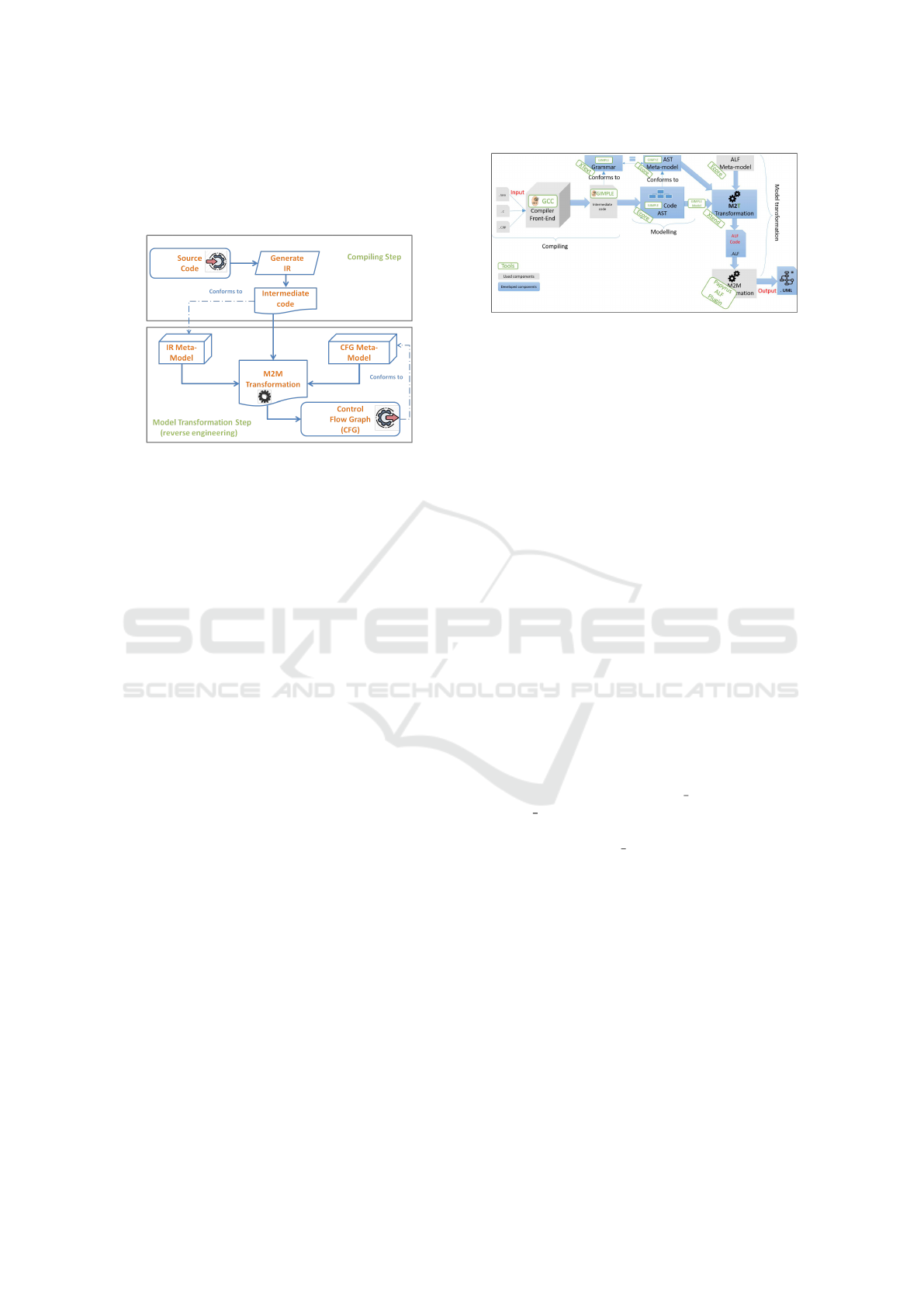
form this transformation, we have to create the target
meta-model which depends on the formalism used to
represent the control flow (i.e., CFG meta-model) and
define the set of transformations rules.
Figure 1: Proposed approach:Detailed steps.
4 TECHNICAL DETAILS AND
IMPLEMENTATION
In this section, we present the developed frame-
work. In order to automate the first step of the pro-
posed approach (i.e., compiling step), we choose the
GNU Compiler Collection GCC (Pop, 2006) (Mer-
rill, 2003) as compiler. The intermediate representa-
tion in GCC is called GIMPLE (Pop, 2006) (Merrill,
2003), which is used in the developed tool to repre-
sent the intermediate code. The second step of the
proposed approach consists in generating a graph that
represents at a higher level of abstraction the control
flow in a given source code. For the developed tool,
UML activity diagram (Cook et al., 2017) has chosen
as a target control flow.
The developed tool is intended to be part of the
Eclipse Papyrus Modelling tool (Guermazi et al.,
2015) which is an industrial-grade open source
Model-Based Software Engineering tool. Indeed, this
work should be integrated into Papyrus as a new re-
verse engineering functionality. To this end, multiple
technical decisions have been considered. Figure 2 il-
lustrates the implementation architecture with focuses
on the tools and technologies considered to automate
each step of the proposed approach.
Technically speaking the proposed approach consists
of three main phases : the first phase generates the
GIMPLE code using the GCC front-end. Since GIM-
PLE is an intermediate language, the intermediate
code conforms the GIMPLE Grammar. The second
phase is the modeling phase which consists in cre-
ating Abstract Syntax Tree (AST) Model. The AST
model is a graph representation of the intermediate
Figure 2: Implementation Architecture.
code semantically equivalent to it and which must
conform to the AST meta-model. The third step, is
the model transformation step. In this step, we chose
to perform a model to text transformation (M2T) from
the intermediate AST model to ALF code (OMG,
2011) instead of doing a model-to-model transforma-
tion. This choice allows to reuse the already available
ALF tool (Seidewitz and Tatibouet, 2015) in Papyrus
which performs a transformation from ALF code to
UML activity diagram.
4.1 Intermediate Code Generation
The current version of the developed tool uses three
of GCC 5.4 front-ends which are gcc, g++ and gcj
for the programming languages C, C++ and JAVA,
respectively. These front-ends were configured to
generate the GIMPLE code. Figure 3 shows an ex-
ample of a conditional statement “if” using GIM-
PLE raw syntax. This GIMPLE code was gener-
ated by compiling a C++ main function using g++.
This code shows how GIMPLE flattens the high ab-
stract statements into lower statements closer to ma-
chine instructions. The “if” statement is decom-
posed into a condition (gimple cond), three labels
(gimple label) that indicates which instructions to
execute in case of a true or false condition and a go
to instruction (gimple goto) to navigate to the next
instruction.
At the end of this phase, we obtain a GIMPLE file
written in its raw syntax. The file contains interme-
diate code that is semantically equivalent to source
code. This code can be processed in the following
steps independently of the original source language.
4.2 AST Model Generation
Since the solution is intended to be part of Eclipse
Papyrus, we need to integrate the results from the
previous phase to the Eclipse development platform.
To ensure this integration we use Eclipse Xtext tool
(Eysholdt and Behrens, 2010) which allows loading
any GIMPLE file in Eclipse and creating an equiv-
MODELSWARD 2022 - 10th International Conference on Model-Driven Engineering and Software Development
214
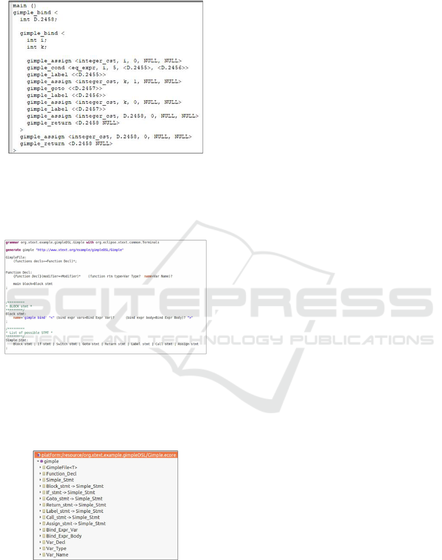
Figure 3: Example of a conditional statement “if” using
GIMPLE raw syntax.
alent model using its language grammar. We create
thus a grammar, using Xtext, for the GIMPLE files
generated by GCC. An excerpt of this grammar is
given in Figure 4.
Figure 4: Excerpt of the Xtext grammar for GIMPLE.
Then, as shown in Figure 5, a meta-model for the
GIMPLE abstract syntax tree (i.e., AST Meta-Model)
in Ecore format is generated. Xtext, produces in addi-
tion a list of JAVA classes for the AST elements which
provides run-time support for the generated instance
model from GIMPLE code (i.e., AST model).
Figure 5: Excerpt of the generated GIMPLE Ecore Meta-
model.
Figure 5 gives an excerpt of the generated meta-
model. It is worth noting that the grammar and the
AST meta-model are created only once. However, we
generate an instance model (i.e., AST model) for each
GIMPLE file in an Eclipse run-time. This AST model
serves as input for the third phase (i.e., the model
transformation).
4.3 UML Activity Diagram Generation
In order to generate ALF code from any obtained
GIMPLE model instance (i.e., AST model), we per-
form a model to text transformation using an Eclipse
code generator called Xtend (Bettini, 2016). The
transformation implements a set of predefined map-
ping rules between the GIMPLE Meta-model and the
ALF meta-model elements. The developed transfor-
mation program using Xtend analyses the GIMPLE
model (i.e., AST model), executes the transformation
rules corresponding to the visited model node, and
generates the equivalent ALF code. Once the ALF
code is generated, we use the ALF tool (Seidewitz and
Tatibouet, 2015) already available in Papyrus which
provides an Xtext based ALF code editor and a com-
piler that executes a Model-to-Model transformation
to generate UML activity diagrams from ALF code.
5 CASE STUDY
This section presents the practical application of the
proposed tool with a simplified case study from the
Papyrus for IoT (Internet of things) Project (Dhouib
et al., 2016). Papyrus for IoT uses an IoT model-
driven methodology to guide the IoT system de-
signer during the development and supervision of IoT
systems. The considered example in this paper is
based on a smart IoT-based home automation system
(Dhouib et al., 2016). More specifically, we are inter-
ested in the temperature management module inside
a smart home. Like any IoT system, this module is
mainly based on three essential parts, namely, a pro-
cessing unit, a sensor and an actuator. In this example,
the processing unit that takes decisions to manage the
temperature of a room, a temperature sensor to pro-
vide data from the environment and two actuators, a
cooler and a heater, to perform temperature changes
in the room.
5.1 Inputs
We have considered as inputs three source codes writ-
ten in three different programming languages which
are C, C++ and JAVA. Figure 6 the C++ source
code.The program describes the behaviour of the tem-
perature management unit. The main code function is
Use of Compiler Intermediate Representation for Reverse Engineering: A Case Study for GCC Compiler and UML Activity Diagram
215
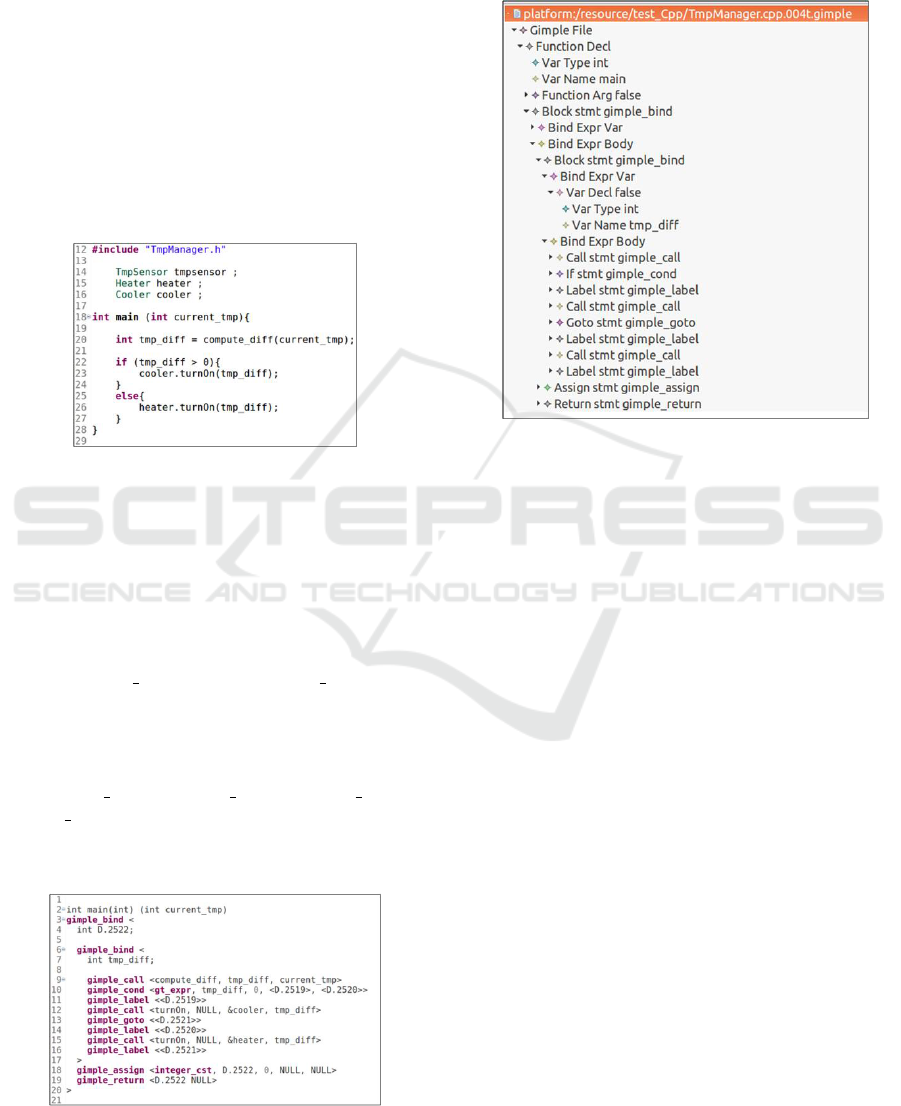
executed regularly in the processing unit to retrieve
the current temperature from the sensor, compare it to
the required temperature set by the user or automat-
ically initialized by the system, then decides to call
either the cooler or the heater.
5.2 Gimple Intermediate
Representation
Once the input code is retrieved, it is automatically
passed through the corresponding compiler front-end
to generate the common intermediate code GIMPLE
and to print it in a dump file using the raw GIMPLE
syntax.
Figure 6: Simplified C ++ code for Temperature Manage-
ment Unit.
Figure 7 shows the generated GIMPLE code from
the C++ source code given as input. Almost the
same GIMPLE is generated from the C and the Java
source code. The main structures of a GIMPLE file
are functions and code blocks. Each method from
source code is transformed into a GIMPLE function
with a name, return type, parameters and a code block
named “gimple bind”. Each “gimple bind” forms
a local context containing a set of local variable dec-
larations followed by a set of instructions executed ei-
ther sequentially or in parallel. The instructions could
be any GIMPLE statement such as another embed-
ded gimple bind, gimple call, gimple assign,
gimple cond, etc. In order to construct the GIMPLE
model instance (i.e., AST model) from the textual
GIMPLE code, we use the developed GIMPLE edi-
Figure 7: Generated GIMPLE code from C ++ code (Figure
6).
tor with the previously created GIMPLE Meta-model
(Figure 5). Figure 8 shows an example of the AST
model generated from the C++ code for the consid-
ered case study.
Figure 8: Generated intermediate GIMPLE Ecore model
from C++ source file of the considered case study.
5.3 ALF Code
From the AST model, the tool runs the Xtend trans-
formation in order to generate ALF code. Figure 9
shows the intermediate ALF codes generated from the
C++ program. It is woth to note here that the ALF
textual representation generation is only a technical
constraint that we have considered to reuse an already
existing compiler developed by the Papyrus Team that
takes as input the ALF representation and procudes
automatically the UML Activity model. One can
argue that developing a compiler from GIMPLE to
UML is an alternative way to generate the UML Ac-
tivity representation. we have choose the first alter-
native to reuse as much as possible the existing ALF
compiler.
5.4 UML Activity Diagram
The last step is the generation of the UML activity di-
agram from the generated ALF code using the already
implemented ALF tool. The model explorer view and
the graphical of the UML activity diagram view pro-
duced from the C++ source file are given respectively
in Figure 10. The activity model describes at high
level the control flow in the source file. It is worth
mentioning that the intermediate results (i.e., Gimple
code, Gimple instance model (AST model) and ALF
MODELSWARD 2022 - 10th International Conference on Model-Driven Engineering and Software Development
216
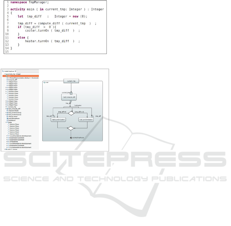
Figure 9: Generated ALF code from C++ file.
Figure 10: Generated UML activity diagram from C++
source file for the considered case study.
code) are transparent for the user of the developed
tool.
Unlike the textual representation of the code
(C,C++,Java) shown in Figure 6 as example, the Fig-
ure 10 shows a graphical representation that is easier
to understand to evaluate and to exchange mainly with
non developer stakeholders. However, the main ben-
efit from having this graphical representation is the
graphical simulation of the code. In fact, Papyrus pro-
vides UML models execution by means of a module
called Moka which aims at providing a generic envi-
ronment for model execution (Guermazi et al., 2015).
Moka natively includes an execution engine for ac-
tive classes behaviors, represented by UML activities.
This Papyrus extension allows the user to simulate its
UML Activity diagram by visualizing the code exe-
cution at the graphical level. this visualization is very
helpful to simulate the execution of the code and to
validate it before its deployment that may be an ex-
pensive task mainly for embedded systems.
6 CONCLUSION
This paper presents a new approach for reverse en-
gineering of behavioural models from source codes.
Firstly, an intermediate representation is generated
from an input source code. Here, we use compiler
front-ends to produce the intermediate code. Then,
a model transformation is performed to generate the
graph that describes the control flow in the source
code. The contributions in this paper can be sum-
marized in three points : (1) We have proposed the
use of compiler in the reverse engineering process in
order to make this transformation independent from
the source programming language. (2) We have de-
veloped a tool that generates UML activity diagrams
from source files using GCC and GIMPLE as inter-
mediate representation. (3) We have applied the pro-
posed approach to an IoT case study. The use of the
developed tool may facilitate and accelerate the com-
prehension, the modernization and the reuse of exist-
ing code, which may increase the productivity during
the development of software embedded systems.
As a possible extension of this work, we plan to
enhance the GIMPLE model and the transformation
to cover more elements such as parallelism, excep-
tions,etc, and provide simulations options for the gen-
erated activity diagrams. The simulation of an activ-
ity diagram have been already tested in a previous
work that concern the design and the execution of
a robot (the Sybot collaborative robot) (Kchir et al.,
2016).Another possible extension is to consider Ar-
tificial Intelligence (AI) techniques. Indeed, we aim
to automatically generate a database for activity dia-
grams from online open source projects (GitHub /Git-
lab, etc.). This database would serve for automatic
transformations using machine learning techniques.
REFERENCES
Atkinson, C. and Kuhne, T. (2003). Model-driven devel-
opment: a metamodeling foundation. IEEE software,
20(5):36–41.
Banti, F., Pugliese, R., and Tiezzi, F. (2011). An accessible
verification environment for uml models of services.
Journal of Symbolic Computation, 46(2):119–149.
Bergmayr, A., Bruneliere, H., Cabot, J., Garc
´
ıa, J., Mayer-
hofer, T., and Wimmer, M. (2016). frex: fuml-based
reverse engineering of executable behavior for soft-
ware dynamic analysis. In 2016 IEEE/ACM 8th In-
ternational Workshop on Modeling in Software Engi-
neering (MiSE), pages 20–26. IEEE.
Bettini, L. (2016). Implementing domain-specific languages
with Xtext and Xtend. Packt Publishing Ltd.
Use of Compiler Intermediate Representation for Reverse Engineering: A Case Study for GCC Compiler and UML Activity Diagram
217

B
´
ezivin, J. (2005). On the unification power of models.
Software & Systems Modeling, 4(2):171–188.
Brauckmann, A., Goens, A., Ertel, S., and Castrillon, J.
(2020). Compiler-based graph representations for
deep learning models of code. In Proceedings of the
29th International Conference on Compiler Construc-
tion, pages 201–211.
Bruneliere, H., Cabot, J., Dup
´
e, G., and Madiot, F.
(2014). Modisco: A model driven reverse engineer-
ing framework. Information and Software Technology,
56(8):1012–1032.
Charfi, A., Boulet, P., and Mraidha, C. (2012). An
optimized compilation of uml state machines. In
11th IEEE International Symposium on Object and
Component-Oriented Real-Time Distributed Comput-
ing (ISORC), pages 172–179, Los Alamitos, CA,
USA. IEEE Computer Society.
Charfi, A., Mraidha, C., Gerard, S., Terrier, F., and Boulet,
P. (2010). Toward optimized code generation through
model-based optimization. 2010 Design, Automation
& Test in Europe Conference & Exhibition (DATE
2010), pages 1313–1316.
Charfi, A., Mraidha, C., Gerard, S., Terrier, F., Boulet,
P., Inria, H. I., Charfi, A., Mraidha, C., G
´
erard,
S., Yvette, G. S., and Boulet, P. Does code gen-
eration promote or prevent optimizations. In in
”Object/Component/Service-Oriented Real-Time Dis-
tributed Computing (ISORC), 2010 13th IEEE Inter-
national Symposium on”, Espagne Parador of.
Cook, S., Bock, C., Rivett, P., Rutt, T., Seidewitz, E., Selic,
B., and Tolbert, D. (2017). Unified modeling language
(UML) version 2.5.1. Standard, Object Management
Group (OMG).
Dhouib, S., Cuccuru, A., Le F
`
evre, F., Li, S., Maggi, B.,
Paez, I., Rademarcher, A., Rapin, N., Tatibouet, J.,
Tessier, P., et al. (2016). Papyrus for iot—a model-
ing solution for iot. Proceedings l’Internet des Objets
(IDO: Nouveaux D
´
efis de l’Internet des Objets: Inter-
action Homme-Machine et Facteurs Humains. Paris,
France.
Eshuis, R. (2006). Symbolic model checking of uml activity
diagrams. ACM Transactions on Software Engineer-
ing and Methodology (TOSEM), 15(1):1–38.
Eysholdt, M. and Behrens, H. (2010). Xtext: implement
your language faster than the quick and dirty way.
In Proceedings of the ACM international conference
companion on Object oriented programming systems
languages and applications companion, pages 307–
309.
Favre, J.-M. (2004). Towards a basic theory to model model
driven engineering. In 3rd Workshop in Software
Model Engineering, WiSME, pages 262–271. Citeseer.
Glass, R. L. (2006). The standish report: does it really de-
scribe a software crisis? Communications of the ACM,
49(8):15–16.
Guermazi, S., Tatibouet, J., Cuccuru, A., Dhouib, S.,
G
´
erard, S., and Seidewitz, E. (2015). Executable mod-
eling with fuml and alf in papyrus: Tooling and exper-
iments. strategies, 11:12.
Jørgensen, M. and Moløkken-Østvold, K. (2006). How
large are software cost overruns? a review of the 1994
chaos report. Information and Software Technology,
48(4):297–301.
Kchir, S., Dhouib, S., Tatibouet, J., Gradoussoff, B., and
Simoes, M. D. S. (2016). Robotml for industrial
robots: Design and simulation of manipulation sce-
narios. In 2016 IEEE 21st International Conference
on Emerging Technologies and Factory Automation
(ETFA), pages 1–8. IEEE.
Kienle, H. M. and M
¨
uller, H. A. (2010). Rigi—an environ-
ment for software reverse engineering, exploration, vi-
sualization, and redocumentation. Science of Com-
puter Programming, 75(4):247–263.
Korshunova, E., Petkovic, M., Van Den Brand, M., and
Mousavi, M. R. (2006). Cpp2xmi: Reverse engineer-
ing of uml class, sequence, and activity diagrams from
c++ source code. In 2006 13th Working Conference on
Reverse Engineering, pages 297–298. IEEE.
Lima, L., Tavares, A., and Nogueira, S. C. (2020). A frame-
work for verifying deadlock and nondeterminism in
uml activity diagrams based on csp. Science of Com-
puter Programming, page 102497.
Martinez, L., Favre, L., and Pereira, C. (2013).
Architecture-driven modernization for software re-
verse engineering technologies. In Progressions and
Innovations in Model-Driven Software Engineering,
pages 288–307. IGI Global.
Merrill, J. (2003). Generic and gimple: A new tree rep-
resentation for entire functions. In Proceedings of the
2003 GCC Developers’ Summit, pages 171–179. Cite-
seer.
Nelson, M. L. (2005). A survey of reverse engineering and
program comprehension. arXiv preprint cs/0503068.
OMG, P. (2011). Action language for foundational uml
(alf).
Ouchani, S., Mohamed, O. A., and Debbabi, M. (2014).
A formal verification framework for sysml activ-
ity diagrams. Expert Systems with Applications,
41(6):2713–2728.
Pop, S. (2006). La repr
´
esentation SSA: s
´
emantique, anal-
yses et impl
´
ementation dans GCC. PhD thesis, Paris,
ENMP.
Raibulet, C., Fontana, F. A., and Zanoni, M. (2017). Model-
driven reverse engineering approaches: A systematic
literature review. IEEE Access, 5:14516–14542.
Seidewitz, E. (2003). What models mean. IEEE software,
20(5):26–32.
Seidewitz, E. and Tatibouet, J. (2015). Tool paper: Com-
bining alf and uml in modeling tools-an example with
papyrus-. OCL@ MoDELS, 1512:105–119.
MODELSWARD 2022 - 10th International Conference on Model-Driven Engineering and Software Development
218
