
Universal Safety Format: Automated Safety Software Generation
Frederik Haxel
1
, Alexander Viehl
1
, Michael Benkel
2
, Bjoern Beyreuther
2
, Klaus Birken
3
,
Rolf Schmedes
4
, Kim Gr
¨
uttner
4
and Daniel Mueller-Gritschneder
5
1
FZI Research Center for Information Technology, Karlsruhe, Germany
2
ScopeSET GmbH, Fischbachau, Germany
3
itemis AG, Stuttgart, Germany
4
OFFIS Institute for Information Technology, Oldenburg, Germany
5
Technical University of Munich, Munich, Germany
{schmedes, gruettner}@offis.de, daniel.mueller@tum.de
Keywords:
Functional Safety, Software Safety Mechanism, Model Transformation, Code Generation, Domain-specific
Language.
Abstract:
The development of safety-critical software requires a significant additional effort compared to standard soft-
ware. Safety mechanisms, e.g., for mitigating hardware errors, have to be designed and integrated into the
functional code. This results not only in substantial implementation overhead, but also reduces the overall
maintainability of the software. In this paper, we present the Universal Safety Format (USF), which enables a
model-driven approach that complies with the separation of concerns principle. Software safety mechanisms
are specified as patterns via a domain-agnostic transformation language, separated from the functional soft-
ware. Various domain-specific tools apply these safety patterns to domain-specific artifacts, such as code or
software architecture models. This enables the reuse of safety patterns in multiple designs as well as in a single
design to artifacts from different domains.
1 INTRODUCTION
Industrial safety standards such as (IEC 61508, 2010)
or (ISO 26262, 2018) for automotive systems re-
quire additional development steps to ensure that a
safety-critical system does not cause harm even in the
presence of random hardware faults. Safety mecha-
nisms are technical solutions to detect faults or con-
trol failures in order to maintain a safe system state.
These mechanisms can be implemented in hardware,
software, or a combination of both. Safety mecha-
nisms implemented in software are becoming increas-
ingly relevant for software-intensive systems, espe-
cially when used in combination with commercial off-
the-shelf hardware. These software safety mecha-
nisms can be integrated at different stages of the soft-
ware development with different abstraction levels,
for example, at software model (Ding et al., 2018;
Hu et al., 2020), source code (Trindade et al., 2014),
or binary level (Didehban and Shrivastava, 2016;
Reis et al., 2005; Didehban et al., 2017; Vankeirs-
bilck et al., 2017). The appropriate selection of the
level of abstraction and the modeling or programming
language (from now on called domain) for integrat-
ing suitable safety mechanisms depends on many as-
pects and is highly application-specific. Nonetheless,
the implementation of safety mechanisms often fol-
lows common patterns which share a general struc-
ture, independent of the application and even across
different domains (Armoush, 2010). While many
methodologies exist to support a safety engineering
process, integrating, and implementing application-
specific software safety mechanisms remains a pre-
dominantly manual process which is error-prone and
time-consuming. Furthermore, adding safety mecha-
nisms inflates the software, which not only increases
the maintenance effort, but often makes it more diffi-
cult to understand the functional software.
In this paper, we present a methodology to auto-
mate the labor-intensive realization of software safety
mechanisms for different domains via the so-called
Universal Safety Format (USF), newly introduced in
this paper. This is achieved by describing safety
mechanism patterns via a domain-agnostic transfor-
Haxel, F., Viehl, A., Benkel, M., Beyreuther, B., Birken, K., Schmedes, R., Grüttner, K. and Mueller-Gritschneder, D.
Universal Safety Format: Automated Safety Software Generation.
DOI: 10.5220/0010784200003119
In Proceedings of the 10th International Conference on Model-Driven Engineering and Software Development (MODELSWARD 2022), pages 155-166
ISBN: 978-989-758-550-0; ISSN: 2184-4348
Copyright
c
2022 by SCITEPRESS – Science and Technology Publications, Lda. All rights reserved
155
mation language and by extending domain-specific
tools to implement the domain-agnostic transforma-
tion in a domain-specific context. Automating this
process also enables the functional software to be kept
separate from the safety mechanisms, as these can be
adapted and integrated at any time. The main contri-
butions of the paper are:
• The domain-agnostic USF metamodel which de-
scribes the structure as well as the data and control
flow of the functional software.
• The USF transformation language (UTL) used to
integrate safety mechanism patterns into a model.
• A methodology to map USF transformations to
domain-specific contexts.
The remainder of this paper is structured as follows:
A brief overview of the safety engineering process is
given in Section 2 as well as the introduction of a run-
ning example. Section 3 illustrates how the USF pro-
cess can be integrated into an existing development
flow. The USF metamodel is described in Section 4,
while Section 5 is dedicated to the UTL. The appli-
cation of the USF methodology is demonstrated on
the introduced running example at model and source
code level in Section 6. The results are discussed in
Section 7 and our approach is compared with related
research in Section 8. Section 9 concludes and de-
scribes future work.
2 SAFETY ENGINEERING IN A
NUTSHELL
Various safety standards exist to minimize the risk
of system failures. They offer guidance on how to
design, deploy and maintain a system for a safety-
related application. One exemplary standard is the
before-mentioned (IEC 61508, 2010), which is ap-
plicable to all industries, while (ISO 26262, 2018) is
an industry-specific adaptation of the former. In order
to get a better impression of the topic of safety engi-
neering, the IEC 61508 standard will be examined in
more detail in the following paragraphs.
The premise of this standard is that any safety-
related system must work correctly or fail in a pre-
dictable and safe manner under all possible stated
conditions. For this purpose, the standard provides
a comprehensive and holistic engineering process
called the safety life cycle. It comprises 16 phases,
starting with analysis, continuing with principles for
realization, and ending with phases on the operation
of a system. All these phases evolve around the cor-
rect execution of safety-related functions. A funda-
mental part of this life cycle is a probabilistic failure
approach that classifies the safety impact of a compo-
nent’s failure. It is part of the hazard and risk analy-
sis which consists of three stages: hazard identifica-
tion, analysis, and risk assessment. For the risk as-
sessment, risk is seen as a function of likelihood of a
hazardous event and the severity of its consequence.
Either qualitative or quantitative analysis techniques
can be used to quantify the risk. This assessment in-
dicates which risks have to be reduced and therefore
allows for an appropriate design of the protective sys-
tem. It renders under- or over-specifying less likely.
To further comply with the standard, safety require-
ments have to be made with a targeted safety integrity
level (SIL). The safety integrity is described as ’the
probability that the safety-related system will satis-
factorily perform the required safety functions under
all stated conditions’. There are four discrete safety
integrity levels which specify the safety integrity re-
quirements for a function. The general reasoning be-
hind SILs goes as follows: for a greater necessary risk
reduction, the safety-related system needs to be more
reliable, so the targeted SIL has to be higher.
(IEC 61508, 2010) and other related safety stan-
dards offer assistance on what safety mechanisms
should be used in order to meet a targeted SIL. Thus,
there is a recurrent set of utilized safety mechanisms
in the development of safety-related systems, some
examples are: error detection logic and codes, plausi-
bility checks, range checks of input and output data,
stack overflow/underflow detection, timing supervi-
sion with watchdogs, control flow monitoring and
external monitoring facilities, static recovery mech-
anisms, hardware self-tests and majority voters. To
foster the wide applicability and reuse of these safety
mechanisms, this paper proposes a specification for-
mat that is not bound to one specific domain.
Running Example
The potential of the USF is illustrated in this paper
on a simplified adaptive cruise control (ACC) system.
Fig. 1 shows an overview of the functionality. The
goal of an ACC is to control the speed of a vehicle
such that it keeps a constant distance to a preceding
vehicle. For this, the system reads its own speed and
the distance to the preceding vehicle, executes a PI
control algorithm, and adjusts its own speed by setting
a new throttle value in the motor.
Running the ACC on an embedded hardware plat-
PI controller
Speed
Sensor
Radar
Sensor
Motor
Figure 1: Adaptive cruise control (ACC).
MODELSWARD 2022 - 10th International Conference on Model-Driven Engineering and Software Development
156
form which may be error-prone can cause safety haz-
ards. Clearly, a major safety hazard may arise, if the
distance to the preceding vehicle is not maintained.
Typical errors in the integrated hardware platform are
either permanent errors due to aging and wear-out ef-
fects or transient errors (so called soft-errors) which
may arise, for example, from particle strikes in the
integrated circuitry. A common method to mitigate
the impact of soft-errors on a calculation is the appli-
cation of a dual modular redundancy (DMR) pattern.
Fig. 2 gives an example of an applied DMR pattern
on the PI controller. The DMR pattern duplicates the
function and compares the two results. If both calcu-
lations yield the same result, the motor throttle is set,
if not, an error handler is triggered.
PI controller
Speed
Sensor
Radar
Sensor
Motor
PI controller
Comparator
Error
Handler
Figure 2: ACC with dual modular redundancy (DMR).
3 WORKFLOW
The USF methodology enables the user to gener-
ate and integrate application-specific safety mecha-
nisms into different domains using one pattern de-
scription per safety mechanism type and the approach
can be integrated into existing functional develop-
ment flows. Fig. 3 gives an overview of a typical
design flow. Based on the functional requirements,
a functional specification is created and subsequently
implemented.
Functional
Requirements
Functional
Specification
Functional
SW
Safety
SW
Safety
Requirements
Safety
Specification
Safe
SW
Selection Generation Integration
ref. ref. ref.
USF Support
Figure 3: Development flow with USF support.
The safety requirements are derived from a safety
analysis of the system and its functional requirements.
Analogous to the functional development, a separate
safety specification is then created that contains the
required software safety mechanism. For the USF
approach, this objective is achieved by selecting and
configuring suitable safety mechanisms from a pre-
defined library of safety mechanism patterns. This
selection represents the safety specification, and the
patterns are stored in a formalized manner. Once the
safety specification is complete, the specification can
be used to implement safety mechanisms fully auto-
matically, i.e., generate the safety software and then
integrate the generated safety software into the func-
tional software, resulting in the final safe software. To
enable automatic safety software generation, the core
of the USF consists of the following two parts:
1. USF metamodel: A domain-agnostic metamodel
to describe the structure of functionality including
the data and control flow.
2. UTL: A transformation language to specify safety
mechanism patterns and how to integrate them
into USF-based models.
The safety pattern library consists of formal specifica-
tions of safety patterns and their corresponding trans-
formation scripts. A predefined set of safety patterns
is provided with the USF , but the library can and
should be extended with each design. A safety pattern
from the library can be easily applied to a USF model
by specifying elements inside the model that should
be protected by the given mechanism and executing
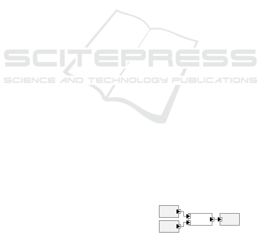
the transformation. Fig. 4 shows the application of a
DMR pattern on a USF component. A detailed de-
scription of the USF metamodel is given in Section 4.
Func
USF
Transformation
USF
Library
DMR
Func_DMR
Func
Func
Comp
Handler
Figure 4: Application of a DMR pattern in USF.
In order to use USF safety mechanisms in a specific
domain, the transformation steps have to be inter-
preted for this domain’s context. This can be au-
tomated by integrating USF support in a domain-
specific tool. There are many implementation options
to achieve this and they depend on the specific do-
main and existing tool infrastructure. One option to
realize the USF support in a tool is to implement the
following four steps:
1. Mapping between the domain and USF elements.
2. Interface to use the safety patterns from the USF
library and to annotate them directly to domain
elements using the mapping.
3. Create a domain-specific USF transformation in-
terpreter using the mapping.
4. Interface for domain-specific implementations of
the newly introduced components (e.g., compara-
tor functions, specific error handlers)
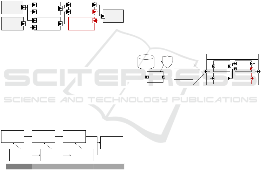
Fig. 5 shows an example for the application of a DMR
mechanism on a section of C code. The C code can be
transformed by interpreting all transformation steps
from the USF transformation script in the C domain
(dark gray), analogous to the transformation in the
Universal Safety Format: Automated Safety Software Generation
157
f
USF
Transformation
DMR
f_DMR
f
f
Comp
Handler
Analogue
USF Model
Domain
Domain
Transformation
…
int r = f(a);
…
…
int r = f(a);
int r_dup = f(a);
if (r != r_dup)
handler();
…
Figure 5: Application of a DMR pattern in C.
USF domain (light gray). The newly added compo-
nents Comparator (Comp) and Handler can for ex-
ample be generated from provided code snippets and
then be integrated into the transformed code. For a
detailed description of the USF transformations and
how to integrate them into a tool see Section 5.
4 USF METAMODEL
The metamodel is the foundation for a comprehensive
tool support and makes sure that all tools are based on
the same concepts. The USF model targets simplicity,
which is often a requirement in the safety domain, and
takes inspiration from SysML to enable low-threshold
entry for model experts. This section gives a brief
overview of the main concepts of the USF metamodel.
The full USF metamodel is available at (USF, 2021).
4.1 Block, Port and Connection
Concepts
The USF metamodel provides the concepts of blocks,
ports, and connections. They are used to represent
the system structure and the data flow of the func-
tional model. The application of the USF has shown
that some patterns have to take the control flow into
account as well. Therefore, the metamodel was en-
hanced by dedicated ports and connections to spec-
ify both data flow and control flow in one model.
Fig. 6 shows the part of the metamodel to describe
both flows. A functional element of a system is mod-
Figure 6: Blocks, ports, and connections.
eled as a Block and is characterized by a BlockType.
An interface to a block is defined by DataFlowPorts,
which can be typed by the USF type concept. Infor-
mation flow between blocks is described by a Data-
FlowConnection connecting two DataFlowPorts.
The direction of the data flow is specified by the
PortDirection. In order to type data ports and pa-
rameters the USF metamodel provides a type concept
with StructType, ArrayType, EnumerationType,
TemplateType, and PrimitiveType. Typical prim-
itive types are integer, string and boolean. More
complex types similar to PortDirection shown in
Fig. 6 can be defined as well. To describe control
flows ControlFlowConnection and ControlFlow-
Port are part of the metamodel. Additional concepts
to describe decisions, fork and join are available as
well, but not described in detail here.
4.2 Safety Pattern Concepts
Safety mechanisms are technical solutions to pro-
tect a functional system. Safety patterns are formal-
ized specifications for a safety mechanism, which are
specified first and then are assigned to elements in the
functional model. Both the pattern specification as
well as its assignment provide the input for the trans-
formation. With this transformation the functional
model will be converted into an enriched model where
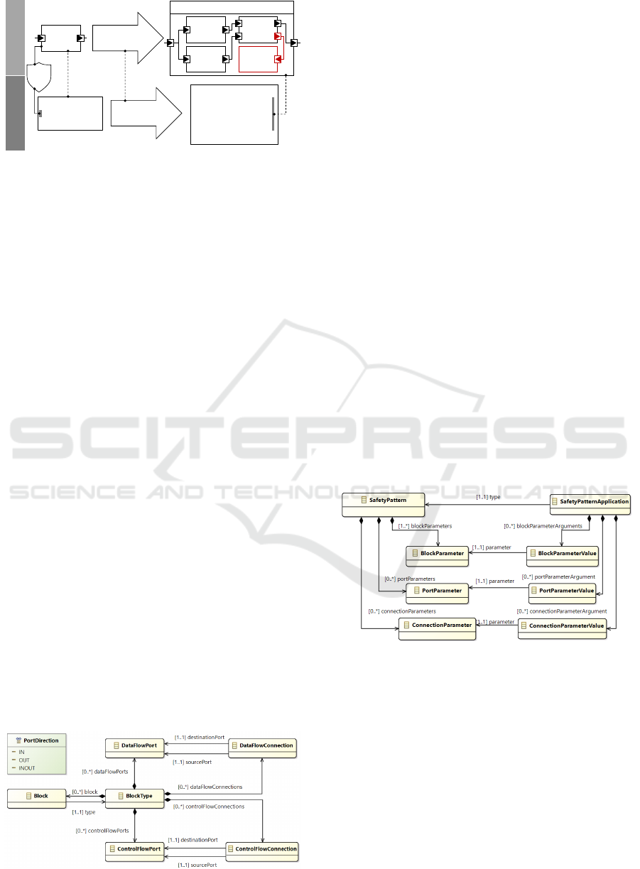
all assigned safety patterns are applied. In Fig. 7 the
main USF concepts for safety patterns are shown.
Figure 7: Safety pattern and safety pattern application.
A SafetyPattern specifies the template with all
the required parameters that are needed for the trans-
formation. A SafetyPatternApplication is an in-
stantiation of a SafetyPattern and is assigned to
system elements. All parameters defined in the tem-
plate are filled with concrete values, which can be
model elements or primitive values to configure the
transformation.
4.3 Pattern Application
As an example, on how to use USF the ACC system
is modeled and a DMR pattern is applied for the con-
MODELSWARD 2022 - 10th International Conference on Model-Driven Engineering and Software Development
158
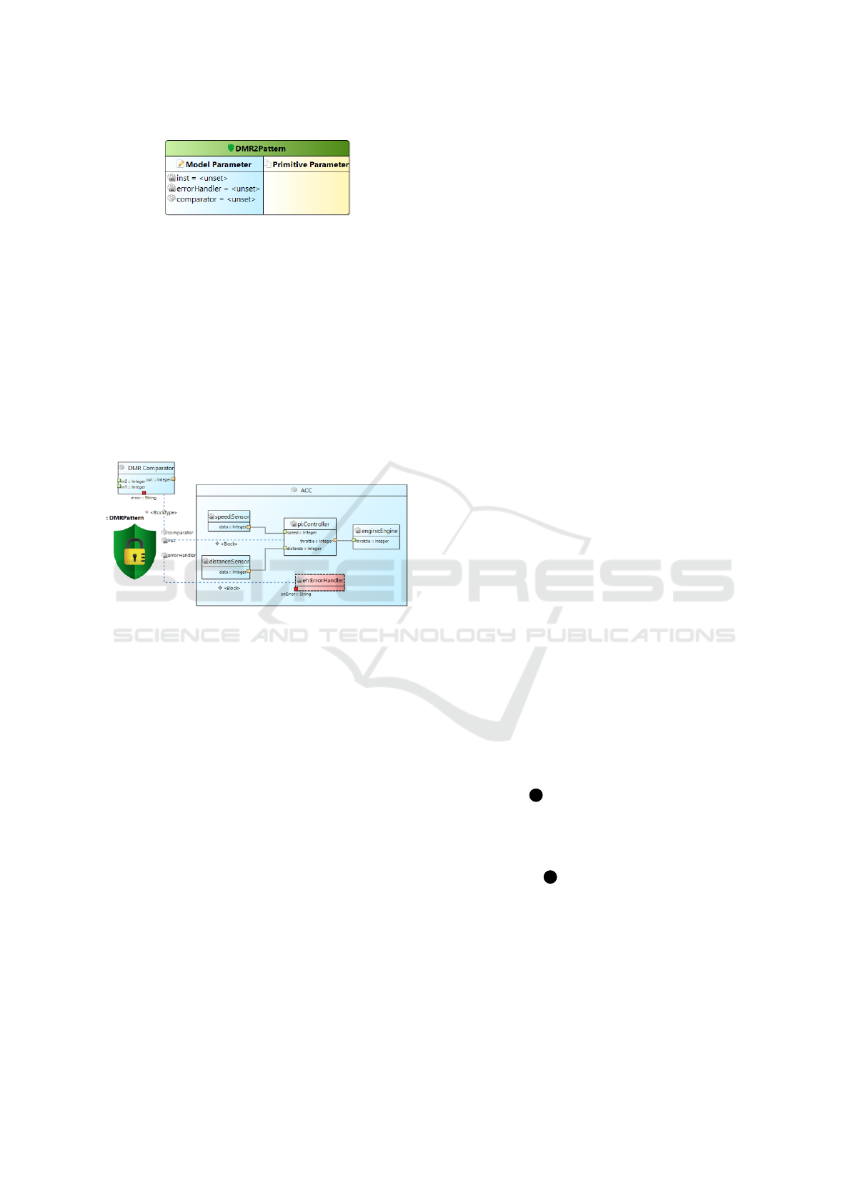
Figure 8: Safety pattern definition.
troller task. Fig. 8 shows the definition of the DMR in
a safety pattern diagram.
A SafetyPattern specifies all required parameters
of a safety mechanism. Required model parameters
are shown in the blue box on the left, additional prim-
itive parameters are listed in the yellow box on the
right. The SafetyPattern can then be assigned to
the functional model in the block diagram by adding
a SafetyPatternApplication and setting up the as-
signment links. In Fig. 9 the USF model of the ACC
example is shown and the DMR safety pattern is as-
signed to the functional block of the controller task.
Figure 9: Safety pattern application.
5 TRANSFORMATION
LANGUAGE
In this section, we describe the transformation lan-
guage which operates on instances of the USF meta-
model, and how transformations can be executed.
Following the terminology of aspect-oriented pro-
gramming (AOP (Kiczales et al., 1997)) we use the
term weaving for the automatic integration of safety
mechanisms.
5.1 Weaving as Model Transformation
The foundation for weaving functional safety mech-
anisms into models and code is a mapping between
these target domains and the USF metamodel. Based
on this mapping, any weaving mechanism can be de-
fined as a model transformation applied to USF mod-
els. We define the USF-specific transformation lan-
guage UTL which provides a convenient way to spec-
ify mechanisms in terms of the domain of USF mod-
els. UTL is an imperative-style language, its basic
entity being a transformation. The language concepts
can roughly be divided into the following parts:
• transformation signatures
• general features (variable definitions, control
structures, function calls)
• operations on concepts from the USF metamodel
• special concepts, esp. the block type constructor
By design, UTL can be expressed using a conve-
nient textual concrete syntax, but can be enriched with
more elaborate notational elements if the tool plat-
form allows it (e.g., when using a projectional editor
like JetBrains MPS (MPS, 2021)).
In order to allow a concise way of specifying
transformations and at the same time provide the tar-
get users (i.e., mostly safety engineers) with a lan-
guage which is easy to use also for non-developers,
UTL is not a general-purpose transformation lan-
guage (compared to e.g., ATL (Jouault et al., 2008)).
The available concepts are restricted to what is re-
quired for specifying safety mechanisms. Moreover,
the restrictions allow easier implementations for vari-
ous target domains.
5.2 Overview of UTL Concepts
5.2.1 Expression Language with Types
UTL features an expression language with the usual
primitive types (e.g., boolean, integer, string) and op-
erations on these types. In addition, a subset of the
block metamodel concepts are available as types in
UTL, e.g., Block, DataPort and ControlPort.
5.2.2 Transformation Signatures
Calling a transformation resembles a function call.
I.e., the transformation signature consists of a name,
a set of named parameters with types and a return
type (see item 1 in Fig. 10). This signature serves
as the transformation’s interface to the annotations in
the domain model or in the USF model. Signatures
might also include block type definitions (according
to the block metamodel). E.g., the transformation
depicted at item 2 in Fig. 10 uses the block type
Comparator<T>.
5.2.3 Operations
The largest part of UTL is the set of operations on
USF model elements. These can be divided into
two groups. The first group of operations are im-
plicitly defined by the USF metamodel (e.g., get-
ters and setters for attributes). The second group
Universal Safety Format: Automated Safety Software Generation
159
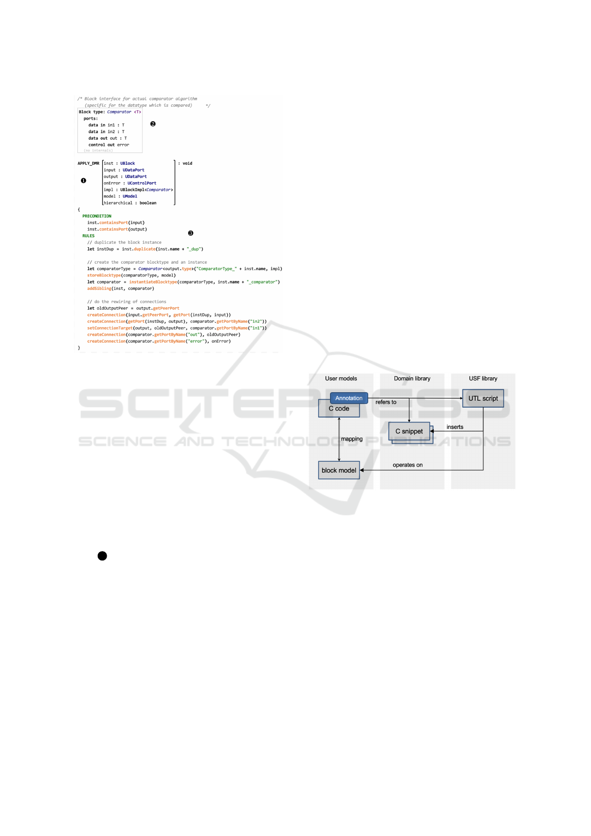
Figure 10: UTL example transformation: DMR mecha-
nism.
consists of helper operations which provide addi-
tional logic or shortcuts for typical patterns (e.g.,
createConnection() for creating new connection
elements and linking them to the proper Port nodes).
5.2.4 Block Type Constructors
A common task in USF transformations is the cre-
ation of new block structures, which is accomplished
by creating a new BlockType element. In order to
avoid building these elements from scratch using the
operations described above, UTL supports construc-
tor syntax. A constructor call creates a new block
type, using an existing one as a blueprint. This is
shown for the Comparator block type in the example
(item 3 in Fig. 10). The blueprint BlockType can
be defined using any USF model editor. In the exam-
ple, it has been defined using a textual syntax as part
of the transformation signature. The first parameter
of the constructor is the name of the new block type.
With the second parameter a domain-specific imple-
mentation of type BlockImpl<T> can be provided.
5.2.5 Abstracting from Domain-specific Details
The USF metamodel and the UTL are domain-
agnostic, but in order to apply transformations to
domain-specific models it is required to handle
domain-specific details. The memento-like pattern
based on BlockImpl<T> and the constructor syntax
can be used to inject domain-specific behavior as im-
plementation of the created block type. E.g., for the
C domain this can be a C code snippet which adheres
to the interface defined by the block type’s ports. The
specific value of the BlockImpl<T> parameter will be
initialized as part of the annotation in the domain and
is ”tunneled” through the transformation script until
the constructor executes.
5.3 Transformation Engine for UTL
UTL allows to model safety mechanisms as domain-
agnostic transformation scripts. The following sec-
tion describes how these scripts can be executed.
5.3.1 Executing Transformations
In an environment for applying USF transforma-
tions to domain-specific models, the following build-
ing blocks are needed: transformation script defined
in UTL, input model (in domain-specific and USF
model representations), library with domain-specific
implementation details (e.g., glue code). This is de-
picted in Fig. 11 using C code as example domain.
Figure 11: Applying transformations (example: C domain).
For execution of transformation scripts, there are dif-
ferent options:
• using an interpreter with a domain-specific back-
end
• translating the input domain-model into a USF
model and executing the transformation generi-
cally
• translating the transformation script into code
(e.g., Java) which can be executed on a represen-
tation of the domain-specific model
The best option for the implementation of a UTL
transformation engine depends on the tool environ-
ment where it has to integrate as well as on the tar-
get domain. Esp. for program code domains (e.g., C
code) the mapping to USF concepts can be complex.
MODELSWARD 2022 - 10th International Conference on Model-Driven Engineering and Software Development
160

5.3.2 Support for Structural Models
The mapping from USF models to target domains
which represent hierarchically structured architec-
tures with components and ports is quite straight-
forward. USF block types and blocks will repre-
sent domain components, and port concepts can of-
ten be mapped 1:1. Hierarchies are natively sup-
ported by USF as well. Therefore, the execution of
UTL transformation scripts on these structures is eas-
ily possible. Typical industry-relevant domains from
this category are SysML (and SysML-like proprietary
models), AUTOSAR, and Simulink. E.g., using the
Eclipse platform Artop (an EMF-based AUTOSAR
implementation (Kn
¨
uchel et al., 2010)) could be inte-
grated with the USF reference implementation (EMF-
based implementation of metamodel and transforma-
tion language) and a transformation engine (e.g., us-
ing Xtend (Xtend, 2021)) for executing the actual
weaving.
5.3.3 Support for Program Code, Esp. C
In compilers and other code-related tools, program
code (e.g., C) is represented as abstract syntax tree
(AST). In order to map this domain to USF, elements
of the AST have to be represented by USF blocks and
other elements. USF has been designed to cover this,
esp. by supporting data flow and control flow con-
cepts. Despite this support the mapping between a C
AST and USF block models is not straightforward. In
our reference implementation, a UTL interpreter with
a domain-specific plug-in has been implemented. The
C domain plug-in creates the USF model from the in-
put C code on the fly, starting from the annotated code
elements (e.g., C functions or C blocks). The UTL in-
terpreter will create new blocks and connections de-
pending on the actual transformation scripts. In a
post-processing step the resulting USF model is con-
verted into C AST elements and manifested as code.
The control flow connections on USF block level de-
termine the order of the newly created C code blocks.
6 EVALUATION
The presented approach is demonstrated by applying
safety patterns at different levels of abstraction to the
development of the ACC software for an embedded
system. To show that the USF approach can be in-
tegrated into an existing tool infrastructure, two tools
are presented first. Then these tools are used to illus-
trate the application of safety patterns.
6.1 Tool Support
In order to validate the concepts of USF, the ap-
proach was successfully applied to several demon-
strators. The functional software of the demonstrators
was provided as C source code, Simulink, or SysML
models. Safety patterns are described and woven into
the functional software by different tools supporting
USF. Safety patterns are provided in a library and can
be readily applied to introduce safety mechanisms in
any functional model. Table 1 shows selected safety
patterns that can be used out-of-the-box.
Table 1: Selected safety patterns supported by USF.
Pattern name Description
DMR Dual modular redundancy
TMR Triple modular redundancy
CRC CRC generation and checks
ESM-ICU External safety mechanism: inter-
rupt controller unit test
Watchdog Hardware watchdog
6.1.1 SafetyModeler
SafetyModeler is a graphical editor to view and cre-
ate USF models. It is provided as an Eclipse plugin
and can be easily installed in an Eclipse Modeling en-
vironment. To instantiate the USF metamodel in a
graphical way was also very useful during the defini-
tion phase of the metamodel and helped to validate it.
The main purposes of SafetyModeler are the
• visualization of functional software in USF
• specification of safety patterns
• definition of safety pattern application
• definition and execution of transformations for
safety patterns
To visualize the functional model the user interface
of SafetyModeler provides several views like model
trees, a drawing canvas with symbol palettes and
property sheets to edit the details of a selected ele-
ment. Functional block models with data and control
flows, definition of data types as well as safety pat-
terns to secure the functional model can be modeled.
Models can also be imported via the XMI interface.
Layout algorithms support the creation of diagrams
in a semi-automated way.
Transformations for safety patterns can be de-
veloped and executed within SafetyModeler as well.
Starting from a safety pattern definition the skeleton
of a transformation is created. The development of
transformation scripts is supported by a language sen-
sitive editor. Finally, the transformation can be exe-
cuted to generate the functional model including the
Universal Safety Format: Automated Safety Software Generation
161
applied safety patterns. This model can be visualized
in SafetyModeler again to prove the proper applica-
tion of safety patterns.
6.1.2 SafetyWeaver
The main focus of the SafetyWeaver tool is to allow
automatic weaving for different target domains, esp.
for programming languages like C. SafetyWeaver is
using the JetBrains MPS platform (MPS, 2021) which
provides great flexibility in terms of notation and
modular combination of languages (Voelter, 2014).
This results in a consistent and intuitive user expe-
rience:
• safety engineers can edit annotations directly in
the C code and still get context-specific propos-
als (e.g., for selecting the proper transformation
script and its parameters, see green elements in
Fig. 14)
• transformation authors can provide online docu-
mentation (e.g., for each transformation and its
parameters) which is presented to transformation
users as type system checks and tooltips
• platform architects who implement the C glue
code can use a code block editor which enforces
the constraints defined by the transformation def-
inition (e.g., data flow input ports represented as
read-only C variables)
• the resulting C code is automatically annotated
with projected trace information, providing trace
links leading back to the applied UTL-scripts, ad-
ditional glue code blocks (traceability, see Fig. 15)
For each transformation script, SafetyWeaver main-
tains a mapping from the feature-rich UTL-language
to a core language using the Shadow Model en-
gine (Voelter et al., 2019a). This allows to simplify
the actual model transformation process, as all syn-
tactic sugar is removed and only the core language
features have to be supported. This is especially valu-
able because the transformations have to be applied
on several different target domains.
SafetyWeaver uses the mbeddr platform (Voelter
et al., 2013) for representing the C code as AST. The
weaving of USF mechanisms is executed by direct in-
terpretation of the UTL transformation scripts. The
C AST is transformed to in-memory USF models dy-
namically; the UTL works on the resulting represen-
tation. Only those parts of the C AST are transformed
which are required for the weaving. As part of the
transformation postprocessing, the output USF model
is optimized (e.g., control flow clean-up), transformed
back to C AST subtrees and integrated into the orig-
inal C AST. This approach allows efficient transfor-
mation even of big C codebases, as only the parts rel-
evant for safety weaving have to be transformed.
6.2 Domain Use-case
In this section, we demonstrate how the previously in-
troduced tools can be used to realize domain-specific
safety mechanisms.
6.2.1 Simulink
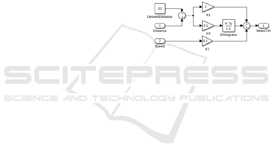
As indicated in Section 2, the core functionality of
the ACC is implemented by a PI controller that adapts
the throttle depending on the distance of the preced-
ing vehicle and the speed of the own vehicle to keep
a fixed distance between them. Fig. 12 shows the im-
Figure 12: PI controller in Simulink.
plementation of the PI controller inside a subsystem
of a MATLAB/Simulink
®
block diagram and can be
directly translated into the C code for the embedded
target via the Simulink Embedded Coder. Same as in
the introductory example, we want to mitigate soft-
errors in the calculation of the PI controller by ap-
plying the DMR pattern to the Simulink subsystem.
To make use of the USF inside of Simulink models a
mapping had to be created once. This was achieved
by directly mapping the appropriate concepts, e.g.,
Simulink blocks to USF blocks, Simulink signals to
USF data flow, etc. The model-to-model transforma-
tion was then realized by using SafetyModeler and the
Simulink support of Eclipse Epsilon (Sanchez et al.,
2019), which supplies an interface to query and mod-
ify Simulink models in Eclipse through the MATLAB
API. By supplying an appropriate Simulink block im-
plementation for the comparator once, we could then
fully automate the application of any DMR pattern
on Simulink blocks. Fig. 13 shows the result of the
model transformation. The resulting Simulink sub-
system was then translated with the Simulink Embed-
ded Coder to C.
6.2.2 Safety-mechanism for C
Additional code is required to execute the C code gen-
erated by Simulink on an embedded system. This in-
cludes code that interacts with the hardware and code
MODELSWARD 2022 - 10th International Conference on Model-Driven Engineering and Software Development
162
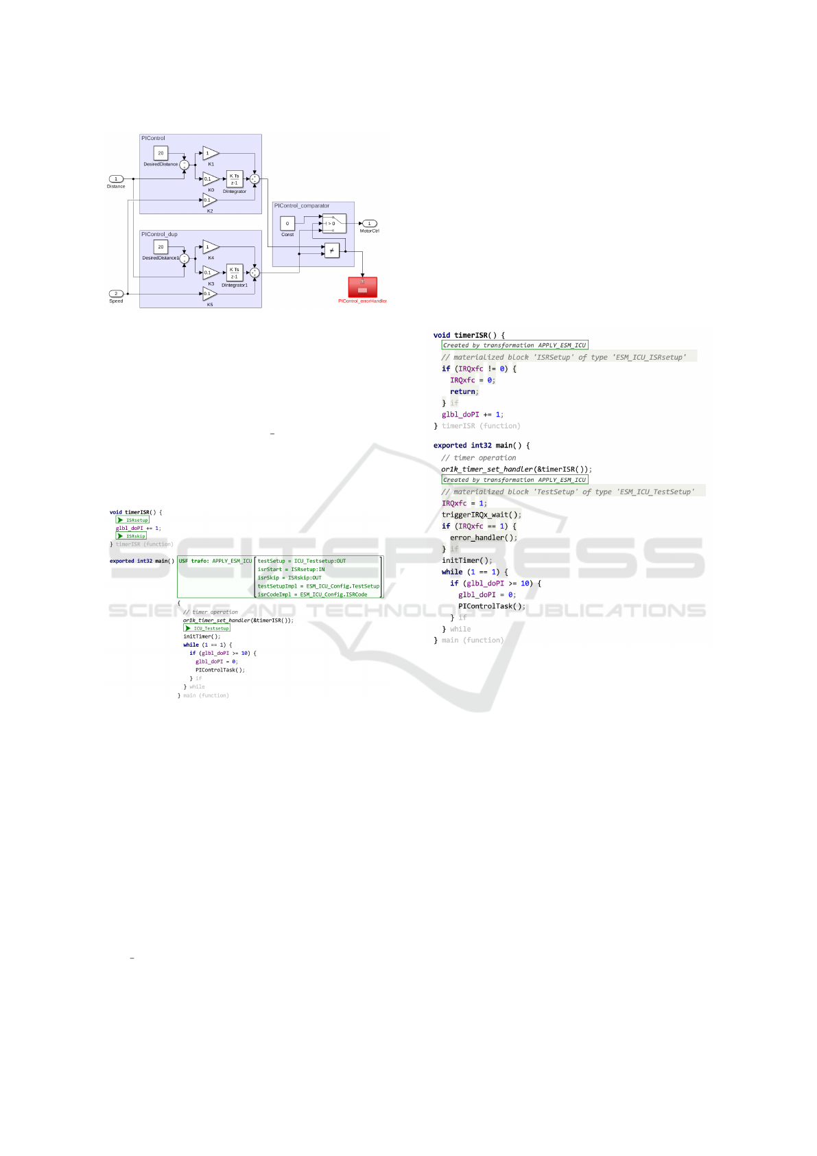
Figure 13: PI controller with applied DMR pattern.
that invokes the generated function from Simulink
(PIControlTask). Fig. 14 illustrates a very simple
implementation of this software.
The main function activates a tick timer. Every
time the timer tick triggers its timer interrupt service
routine (ISR), a counter glbl doPI is incremented.
The main function is kept in an endless while loop
until the counter reaches 10 and then triggers once the
control task and resets the timer counter again to zero,
hence, every ten ticks the control task is executed.
Figure 14: Embedded code of ACC control SW with se-
lected safety mechanism to test ICU at power reset (before
transformation).
A hardware fault could lead to an error in the interrupt
control unit (ICU) such that the ISR is not triggered
on a timer tick. In this case, the control would never
become active after the software started execution be-
cause the ticks are lost. Therefore, an ICU self-test
should be inserted as a safety mechanism, which tests
once at the start of the system software that the timer
ISR is triggered correctly.
This can be done via the SafetyWeaver tool as
shown in Fig. 14. The code positions marked in green
are selected by the user. They mark the position where
the test is set up after the start of the main function
(ICU
Testsetup) as well as two positions in the ISR
(ISRsetup, ISRskip), needed to mark the ISR start and
end.
The safety transformation inserts two new code
blocks into the C source code for both functions (main
and timer ISR). This is shown in Fig. 15. The code
blocks implement the inserted safety mechanism. In
a nutshell, the main function sets a flag IRQxfc and
triggers the timer ISR once via a special function. The
timer ISR unsets the flag. The main function checks
that the ISR was executed and the flag is unset. If it
detects that the flag is still set, then the ISR did not ex-
ecute correctly due to a hardware error. In this case,
the safety mechanism calls an error handler to report
the hardware problem.
Figure 15: Embedded code of ACC control SW with in-
serted safety mechanism to test ICU at power reset (after
transformation).
7 DISCUSSION
The evaluation illustrated how the USF approach can
be applied to generate and integrate software safety
mechanisms. Naturally, this approach requires an ini-
tial development effort to enable the generation. As
mentioned earlier, tool implementations can be com-
plex, but only need to be carried out once per domain.
Adding new patterns via the UTL, on the other hand is
fairly easy, especially with the tool support. However,
to enable the generation of the software, implementa-
tions for certain pattern parts, such as the comparator,
must be supplied or generated once per domain. Since
these parts usually represent a simple functionality,
most of them are fairly easy to implement and the ef-
fort can be reduced by reusing the parts in several pat-
terns. However, in certain cases, such as a timer for
Universal Safety Format: Automated Safety Software Generation
163

bare metal software without a hardware abstraction
layer, multiple implementations can be required de-
pending on the hardware timer used. However, with
this initial setup the reuse of safety patterns in dif-
ferent stages of the design as well as across different
designs is enabled.
For the sake of brevity, we only described the gen-
eration of two mechanisms in detail in this paper. In
our evaluation of the approach, we analyzed further
software safety mechanism used in industry to create
the initial safety pattern library. These patterns can be
divided into application-specific and non-application-
specific patterns. The application-specific patterns,
such as the DMR, have to be adapted to the func-
tionality and interwoven into the functionality often
deep inside the software. Because of this, the reuse
of application-specific patterns in conventional devel-
opment is often very limited and instead resulted in a
manual re-implementation of the safety mechanism.
With the USF approach, these steps can now be auto-
mated. The non-application-specific patterns, such as
the ICU test, don’t have to be adapted to the function-
ality, but still have to be interwoven into the software.
Examples for these patterns are the recommendations
in safety manuals often provided from hardware man-
ufacturers for their platforms. Similar to the conven-
tional development, some effort is required to adapt
to a new hardware platform, but the mechanisms can
be shared between projects using the same hardware.
While the benefit of using the USF approach for some
of these mechanisms is reduced to only an automatic
integration of existing implementations or may only
be useful in certain domains, it can still be very bene-
ficial to express these via pattern. Following the prin-
ciple of separation of concerns, the USF keeps the
functional and safety software separate, but can com-
bine them at any time by using tools such as Safety-
Weaver , making the code easier to maintain, as seen
in Fig. 14 and Fig. 15, easier to maintain. Further-
more, describing all mechanism via USF pattern en-
ables the creation of a formalized safety specification.
As described in Section 2, the realization of soft-
ware safety mechanism is one part of the bigger safety
engineering process and must be viewed in this con-
text. This implies that the safety mechanisms have
to be developed according to the strict rules of the
safety standards and appropriate patterns have to be
selected. The safety engineer is responsible for this
selection and it not only includes that certain errors
are detected and handled, but also that timing and
memory constraints can be met. This can be a com-
plicated trade-off, as some safety mechanisms may
create enormous overhead that can conflict with the
hard deadlines of the application. Automating the re-
alization of safety mechanisms can also improve this
process by enabling the safety engineer to evaluate
different design alternatives faster.
8 RELATED WORK
8.1 System Modeling and Model
Transformations
SysML (Mann, 2009) is a standardized language for
modeling systems. Its profile mechanism has been
used to specialize its generic metamodel and diagrams
in order to support functional safety aspects of sys-
tems, e.g., for model-based dependability analysis in
the aerospace domain (Steurer et al., 2018). The USF
metamodel as a domain-specific language (DSL), on
the other hand, allows the streamlined combination
of structural aspects as well as control/data flow in
the same model. Using a DSL avoids the artificial
complexity of a generic, stereotype-based modeling
approach, providing benefits both for manual editing
and automated model transformations to/from USF.
There are several useful ways of applying
DSLs and model-to-model transformations for safety-
critical system development. Aside from weaving
safety mechanisms into functional code as described
here, the language workbench MPS has been used
for complete generation of safety-critical code and
tests from DSL-based models (Voelter et al., 2019b).
Yet another aspect is the generation of fault-trees
from SysML-like component models using JetBrains
MPS (Munk and Nordmann, 2020).
In this paper, automatic weaving is implemented
as model-to-model transformations supported by the
UTL-language. The general approach is inspired
by the aspect-oriented programming (AOP (Kicza-
les et al., 1997)) methodology. However, USF
safety weaving is not AOP in the strict sense, as
USF patterns might be applied to different target do-
mains (not only to source code of a single program-
ming language). Moreover, the languages, metamod-
els and annotations for USF are specialized for the
functional-safety domain.
For the definition of transformations on generic
metamodels, a variety of languages and correspond-
ing implementations has been developed. QVT (Bast
et al., 2005) is a standardized transformation/query
language operating on models which conform to
MOF 2.0. ATL (Jouault et al., 2008) is a QVT-like
language for EMF models. Viatra2 (Bergmann et al.,
2011) is also a query/transformation language oper-
ating on EMF models, but with a high-performance
incremental implementation. Xtend (Xtend, 2021) is
a general-purpose programming language with spe-
MODELSWARD 2022 - 10th International Conference on Model-Driven Engineering and Software Development
164

cial focus on model-to-model transformations. While
all these approaches could be used to specify safety
mechanisms for the EMF-based USF-models, UTL
has been designed to meet the specific needs of safety
engineers. It uses script-like, imperative control con-
structs instead of generic declarative, graph-based ab-
stractions. It provides special features (e.g., construc-
tor syntax) to create parts of the output by-example
and allows transformation execution on different tar-
get domains (e.g., models or C code).
8.2 Safety Mechanism Generation for
Model-driven Development
The model-driven application of safety mecha-
nisms has only been sparsely addressed in research.
Nonetheless, some approaches exist to integrate
safety mechanisms via transformations on a given
model (Trindade et al., 2014; Ding et al., 2018;
Hu et al., 2020). The authors of (Trindade et al.,
2014) present a method to generate boundary checks
from semi-formal requirements for AUTOSAR soft-
ware components. In (Ding et al., 2018) a flow is
presented to integrate different computational redun-
dancy mechanism, e.g., DMR, into Simulink models
and the authors of (Hu et al., 2020) describe an ap-
proach to apply N-version programming in the Cyber-
Physical Action Language (CPAL). These model-
driven approaches share many advantages, as even
complex safety mechanisms can be introduced early
into the design and are often platform independent.
Furthermore, as the model-based design is usually
easier to understand, than for example only the source
code, this also eases the validation effort of the safety
engineer. While these approaches offer good result,
they are limited to one type of safety mechanism and
only support one domain.
8.3 Code Transformation Methods
When applying the presented model-based flow at
code level, the code modifications defined in the
transformation language are a source-to-source (S2S)
code transformation. They were implemented in an
industrial S2S tool SafetyWeaver, but can be equally
implemented in other C/C++ frameworks such as
LLVM (Lattner and Adve, 2004) or the Rose Com-
piler (Quinlan and Liao, 2011).
Another important class of code transformations
are so-called SW-implemented HW fault tolerance
(SIHFT). These methods do not add additional safety
code but add instruction redundancy to detect tran-
sient hardware errors in the processor similar to the
shown DMR patterns. Different variants exist to pro-
tect load and stores (Didehban and Shrivastava, 2016;
Reis et al., 2005) as well as branches (Didehban et al.,
2017). Other methods add signatures to code basic
blocks to detect illegal jumps (Vankeirsbilck et al.,
2017). SIHFT methods work at the immediate code
or assembly code level and are usually integrated into
backend of the compiler. For the presented model-
based safety flow, these methods can be integrated.
For this, USF transformations add additional code to
indicate to the compiler, which SIHFT methods to ap-
ply to which function of the SW.
9 CONCLUSIONS
In this paper, we presented a model-driven ap-
proach to automatically adapt, generate, and integrate
domain-specific software safety mechanisms via the
newly introduced Universal Safety Format. Safety
mechanisms are generalized by patterns described via
the domain-agnostic transformation language UTL,
which operates on USF models. The safety patterns
form a library and can be reused in different designs
and different design stages. We have shown how
to integrate USF support into domain-specific tools,
which then can apply USF safety patterns in a domain
context to generate and integrate the software safety
mechanisms. Our evaluations show how this can be
realized for very different domain contexts such as
Simulink models or C code using the same pattern
library. Further information and open-source imple-
mentations are available at (USF, 2021).
In future work, we are planning to extend the li-
brary of safety patterns to support a broader range of
mechanisms as well as integrating the USF into more
domain-specific tools to further facilitate an easy au-
tomatic integration of safety mechanisms in different
domains for the end-user. Furthermore, we are inves-
tigating how this approach can be extended to include
the generation of security mechanisms.
ACKNOWLEDGEMENTS
This work is supported by the German Ministry
of Science and Education (BMBF) in the project
SAFE4I under grant 01IS70320.
REFERENCES
Armoush, A. (2010). Design patterns for safety-critical em-
bedded systems. PhD thesis, RWTH Aachen Univer-
sity, Aachen. Aachen, Techn. Hochsch., Diss., 2010.
Universal Safety Format: Automated Safety Software Generation
165

Bast, W., Murphree, M., Michael, L., Duddy, K., Belaunde,
M., Griffin, C., Sendall, S., Didier, V., Steel, J., Tratt,
L., Helsen, S., Venkatesh, R., and Blanc, X. (2005).
Mof qvt final adopted specification: meta object facil-
ity (mof) 2.0 query/view/transformation specification.
Technical report, Object Management Group.
Bergmann, G., Ujhelyi, Z., R
´
ath, I., and Varr
´
o, D. (2011).
A graph query language for emf models. In Cabot, J.
and Visser, E., editors, Theory and Practice of Model
Transformations, Fourth International Conference,
ICMT 2011, Zurich, Switzerland, June 27-28, 2011.
Proceedings, volume 6707 of Lecture Notes in Com-
puter Science, pages 167–182. Springer, Springer. Ac-
ceptance rate: 27%.
Didehban, M. and Shrivastava, A. (2016). Nzdc: A com-
piler technique for near zero silent data corruption. In
Proceedings of the 53rd Annual Design Automation
Conference, DAC ’16, New York, NY, USA. Associa-
tion for Computing Machinery.
Didehban, M., Shrivastava, A., and Lokam, S. R. D. (2017).
Nemesis: A software approach for computing in pres-
ence of soft errors. In 2017 IEEE/ACM Interna-
tional Conference on Computer-Aided Design (IC-
CAD), pages 297–304.
Ding, K., Morozov, A., and Janschek, K. (2018). More:
Model-based redundancy for simulink. In Gallina,
B., Skavhaug, A., and Bitsch, F., editors, Com-
puter Safety, Reliability, and Security, pages 250–264,
Cham. Springer International Publishing.
Hu, T., Cibrario Bertolotti, I., Navet, N., and Havet, L.
(2020). Automated fault tolerance augmentation in
model-driven engineering for CPS. Computer Stan-
dards and Interfaces, 70:103424.
IEC 61508 (2010). Functional safety of electrical/elec-
tronic/programmable electronic safety-related sys-
tems (e/e/pe, or e/e/pes. Standard, The International
Electrotechnical Commission, Geneva, CH.
ISO 26262 (2018). Road vehicles – Functional safety. Stan-
dard, International Organization for Standardization,
Geneva, CH.
Jouault, F., Allilaire, F., B
´
ezivin, J., and Kurtev, I. (2008).
ATL: A model transformation tool. Science of Com-
puter Programming, 72(1):31–39. Special Issue on
Second issue of experimental software and toolkits
(EST).
Kiczales, G., Lamping, J., Mendhekar, A., Maeda, C.,
Lopes, C. V., Loingtier, J., and Irwin, J. (1997).
Aspect-oriented programming. In Aksit, M. and
Matsuoka, S., editors, ECOOP’97 - Object-Oriented
Programming, 11th European Conference, Jyv
¨
askyl
¨
a,
Finland, June 9-13, 1997, Proceedings, volume 1241
of Lecture Notes in Computer Science, pages 220–
242. Springer.
Kn
¨
uchel, C., Rudorfer, M., Voget, S., Eberle, S., Sezestre,
R., and Loyer, A. (2010). Artop – an ecosystem ap-
proach for collaborative aut osar tool development. In
ERTS2 2010, Embedded Real Time Software & Sys-
tems.
Lattner, C. and Adve, V. (2004). Llvm: a compilation
framework for lifelong program analysis amp; trans-
formation. In International Symposium on Code Gen-
eration and Optimization, 2004. CGO 2004., pages
75–86.
Mann, C. (2009). A practical guide to SysML: The systems
modeling language. Kybernetes, 38.
MPS (2021). Meta Programming System (MPS) by
JetBrains. https://www.jetbrains.com/mps/. Last
checked on Nov 29, 2021.
Munk, P. and Nordmann, A. (2020). Model-based safety as-
sessment with SysML and component fault trees: ap-
plication and lessons learned. Software and Systems
Modeling, 19(4):889–910.
Quinlan, D. and Liao, C. (2011). The ROSE source-to-
source compiler infrastructure. In Cetus users and
compiler infrastructure workshop, in conjunction with
PACT, volume 2011, page 1. Citeseer.
Reis, G. A., Chang, J., Vachharajani, N., Rangan, R., and
August, D. I. (2005). SWIFT: Software Implemented
Fault Tolerance. In International Symposium on Code
Generation and Optimization, pages 243–254. IEEE.
Sanchez, B., Zolotas, A., Hoyos Rodriguez, H., Kolovos,
D., and Paige, R. (2019). On-the-fly translation and
execution of ocl-like queries on simulink models. In
2019 ACM/IEEE 22nd International Conference on
Model Driven Engineering Languages and Systems
(MODELS), pages 205–215.
Steurer, M., Morozov, A., Janschek, K., and Neitzke, K.-P.
(2018). Sysml-based profile for dependable UAV de-
sign. IFAC-PapersOnLine, 51(24):1067–1074. 10th
IFAC Symposium on Fault Detection, Supervision
and Safety for Technical Processes SAFEPROCESS
2018.
Trindade, R. F. B., Bulwahn, L., and Ainhauser, C.
(2014). Automatically generated safety mechanisms
from semi-formal software safety requirements. In
Bondavalli, A. and Di Giandomenico, F., editors,
Computer Safety, Reliability, and Security, pages 278–
293, Cham. Springer International Publishing.
USF (2021). Universal Safety Format - Website. https:
//www.universalsafetyformat.org/. Last checked on
Nov 29, 2021.
Vankeirsbilck, J., Penneman, N., Hallez, H., and Boydens,
J. (2017). Random Additive Signature Monitoring for
Control Flow Error Detection. IEEE Transactions on
Reliability, 66(4):1178–1192.
Voelter, M. (2014). Generic Tools, Specific Languages. PhD
thesis, Delft University of Technology.
Voelter, M., Birken, K., Lisson, S., and Rimer, A. (2019a).
Shadow models: Incremental transformations for
MPS. In Proceedings of the 12th ACM SIGPLAN In-
ternational Conference on Software Language Engi-
neering, SLE 2019, page 61–65, New York, NY, USA.
Association for Computing Machinery.
Voelter, M., Kolb, B., Birken, K., Tomassetti, F., Alff,
P., Wiart, L., Wortmann, A., and Nordmann, A.
(2019b). Using language workbenches and domain-
specific languages for safety-critical software devel-
opment. Software & Systems Modeling, 18(4):2507–
2530.
Voelter, M., Ratiu, D., Kolb, B., and Schaetz, B. (2013).
mbeddr: Instantiating a language workbench in the
embedded software domain. Automated Software En-
gineering, 20(3):339–390.
Xtend (2021). Xtend programming language home-
page. http://www.eclipse.org/xtend. Last checked on
Nov 29, 2021.
MODELSWARD 2022 - 10th International Conference on Model-Driven Engineering and Software Development
166
