
Semi-automatic Integrated Safety and Security Analysis
for Automotive Systems
Markus Fockel
1
, David Schubert
1
, Roman Trentinaglia
1
, Hannes Schulz
2
and Wolfgang Kirmair
2
1
Software Engineering & IT Security, Fraunhofer IEM, Paderborn, Germany
2
BMW Group, Munich, Germany
Keywords:
Safety and Security by Design, Modal Sequence Diagrams, Fault Tree Analysis.
Abstract:
There is a steady trend towards increasing the connectivity of vehicles – especially for realizing automated
driving functions. This also increases the attack surface, which is crucial due to the safety-criticality of vehi-
cles. Hence, engineering methods are required, that account for both security and safety, and identify conflicts
and synergies. However, in the automotive domain, newly introduced security analysis methods meet well-
established safety analysis methods. Both are applied in separate silos which hinders communication and
increases development effort. In this paper, we introduce an integrated safety and security analysis method
that supports the analysis of correlations between attacks and hazards on an architectural level. It integrates
with an existing model-based requirements engineering method, and automates modeling and analysis steps
to foster regular communication with low effort in early development phases. We evaluated the approach in a
case study with an automated driving function.
1 INTRODUCTION
There is a steady trend towards increasing the con-
nectivity of vehicles to realize new functionality in
the areas of infotainment or automated driving. While
this trend opens new and mandatory market opportu-
nities it also increases the attack surface of the vehi-
cles (Sommer et al., 2019). This is particularly cru-
cial because we are facing a safety-critical domain
where lifes might be threatened by security-related
incidents. Thus, engineering methods to secure these
systems come into focus. This is underlined by the re-
lease of new security standards like ISO 21434 (ISO,
2020) or UNECE WP.29.
These newly introduced security-related methods
meet well established functional safety methods of
the automotive domain. Both types of methods are
not clearly separable as they share the goal to pro-
tect the lifes of passengers and other people. How-
ever, where security-related methods assume an at-
tacker with malicious intent to alter the system in-
tegrity, safety-related methods assume internal issues
like programming faults or hardware wear-out.
Despite academic effort being invested in re-
searching the unification of safety and security anal-
yses, in practice, safety and security methods are ap-
plied in silos (Lisova et al., 2019) and their integra-
tion is to a large extend manual, time-consuming, and
error-prone. Furthermore, existing integrated analy-
sis methods lack process definitions for joint specifi-
cation and analysis by safety and security engineers.
In this paper, we present a method to support
safety and security engineers in finding synergies or
potential conflicts between their fields. Our contribu-
tion is a tool-supported integrated analysis method to
increase and automate the information exchange be-
tween the corresponding silos. We target methods that
are conducted in early development phases and oper-
ate on an architectural level. In these phases, the in-
formation exchange is particularly important because
untuned decisions may result in time-consuming and
expensive problems that will not become apparent un-
til integration phases. Furthermore, we validate our
approach by means of a case study of an automated
Level 3 driver assistance system (SAE, 2021) that we
refer to as Highway Driving System.
The remainder of this paper is structured as fol-
lows: In Section 2, we discuss related work. Section 3
sketches our running example. Thereafter, we intro-
duce our semi-automatic integrated safety and secu-
rity analysis method in Section 4. In Section 5, we
explain the performed evaluation using the method’s
tool-support. Lastly, Section 6 concludes our work
and provides an outlook on future work.
Fockel, M., Schubert, D., Trentinaglia, R., Schulz, H. and Kirmair, W.
Semi-automatic Integrated Safety and Security Analysis for Automotive Systems.
DOI: 10.5220/0010778500003119
In Proceedings of the 10th International Conference on Model-Driven Engineering and Software Development (MODELSWARD 2022), pages 147-154
ISBN: 978-989-758-550-0; ISSN: 2184-4348
Copyright
c
2022 by SCITEPRESS – Science and Technology Publications, Lda. All rights reserved
147

2 RELATED WORK
In safety engineering, Failure Mode and Effects Anal-
ysis (FMEA) (IEC, 2006a) and Fault Tree Analysis
(FTA) (IEC, 2006b) are established analysis meth-
ods to identify failures and their effects (e.g., haz-
ards) (IEC, 2003). In security engineering, STRIDE
(Shostack, 2014) is an established method to ana-
lyze a system for threats (so-called threat modeling),
and Attack Trees (Schneier, 1999) are used to an-
alyze attack paths, combinations, and effects. In-
tegrated safety and security analysis methods were
evaluated in a literature survey (Lisova et al., 2019).
They identified several security-informed safety anal-
ysis (e.g., the FMVEA (Schmittner et al., 2014) or
the SAHARA approach (Macher et al., 2015)) and
combined safety and security analysis approaches.
These analyses target system safety, taking the effect
of identified threats and planned security measures
into account. An example related to our approach are
Security-enhanced Component Fault Trees (SeCFTs)
introduced in (Steiner and Liggesmeyer, 2015) that
extend Component Fault Trees (CFTs) that were in-
troduced to improve FTA on component-based ar-
chitectures (Kaiser et al., 2003). However, Steiner
and Liggesmeyer do not define an integration of the
method into the development process and do not pro-
vide any automated steps to ease process integration.
A combined safety and security analysis targets
system safety and system security in a unified ap-
proach, i.e., taking hazards, threats, safety measures,
and security measures into account at the same time.
For example, Rujiters et al. define a meta model for
Attack Fault Trees (AFTs) together with three bidi-
rectional model transformations (Ruijters et al., 2017)
to describe interrelations of failure and attack events.
However, Rujiters et al. do not define an integration
of the method into the development process.
In conclusion, analysis methods that integrate
safety and security information exist but lack integra-
tion and process definitions for joint specification and
analysis by safety and security engineers. In this pa-
per, we specify an integrated analysis approach able to
automatically derive safety- and security-relevant in-
formation from model-based requirements engineer-
ing artifacts.
3 EXAMPLE USE CASE
This section introduces the Highway Driving System
that we use as a running example throughout this pa-
per. The system uses the vehicle’s sensors, GPS, and
an HD map received from the cloud to determine its
position and plan its movement trajectory. Its au-
tonomous function imposes hazards for the passen-
gers as well as for other road users (e.g., by causing
an accident). Furthermore, the connectivity required
to make autonomous decisions, results in threats to
the system (e.g., an attacker controlling the vehicle).
The system may only operate on highways. Once
it leaves a highway it has to return vehicle control to
the driver. Hence, the system always needs to know if
it is on a highway and if it is about to leave it (to give
the driver enough time to take over). In this paper, we
focus on the required adequacy calculation that deter-
mines how adequate it is for the system to operate in
the current driving situation. Figure 3 shows the rele-
vant components of this part of the system as a static
architecture using a UML component diagram.
The MapClient receives HD map tiles from the
cloud. To determine the vehicle’s current position on
the map, the system uses two sources: vehicle sen-
sors (including cameras) and GPS. The SensorMatcher
matches identified objects from the vehicle surround-
ings (e.g., lane markings and road signs) to elements
denoted in the HD map. This information is used to
identify the vehicle’s position on the map. The re-
sult is sent as a MapLink to the AdequacyCalculation.
The GPSMatcher identifies the vehicle’s position on
the map via GPS, and also sends a MapLink to the Ade-
quacyCalculation.
Based on the MapLinks, the AdequacyCalculation de-
termines the adequacy of operation for the current po-
sition. For that, it receives adequacy values for each
position on the HD map from the MapClient. Posi-
tions on a highway have an adequacy value close to
100%, positions on an exit lane have a lower value.
Afterward, it matches the current position on the map
(i.e., the combined MapLinks) to the corresponding ad-
equacy value and sends the result to the component
PredictionAndPlanning.
The PredictionAndPlanning plans the trajectory for
autonomous driving based on inputs not detailed in
the figure. If the AdequacyCalculation allows its opera-
tion, it sends the trajectory to other vehicle systems to
actuate steering and acceleration.
To specify the sketched behavior of the Highway
Driving System as model-based requirements, we use
Modal Sequence Diagrams (MSDs) (Harel and Maoz,
2008) adapted for the use with component-based ar-
chitectures (Holtmann and Meyer, 2013). Figure 1
shows a sample MSD representing a requirement for
the AdequacyCalculation. Messages with a dashed line
are not required to occur but listened for. If they do
not occur, the MSD is discarded and the requirement
is not violated. The message with a solid line is re-
quired to be sent if the execution of the MSD from
MODELSWARD 2022 - 10th International Conference on Model-Driven Engineering and Software Development
148
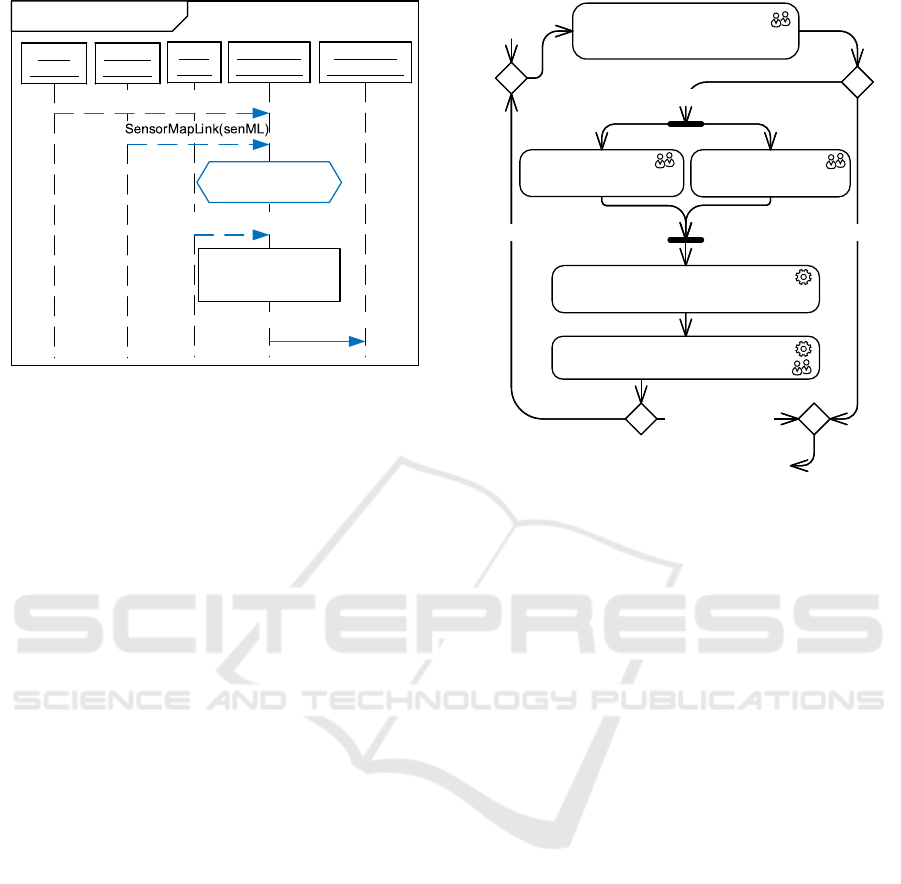
msd AdequacyCalculationmsd AdequacyCalculation
:GPS
Matcher
:GPS
Matcher
:Sensor
Matcher
:Sensor
Matcher
:Map
Client
:Map
Client
:Adequacy
Calculation
:Adequacy
Calculation
:Prediction
AndPlanning
:Prediction
AndPlanning
PositionAdequacy(posA)
«PlausibilityCheck»
{gpsML, senML}
«ValueDependency»
posA dependsOn
{gpsML, senML, allA}
MapTileAdequacies(allA)
GPSMapLink(gpsML)
Figure 1: MSD requirement for the AdequacyCalculation.
top to bottom reaches it. If it is not sent, the require-
ment is violated.
If the AdequacyCalculation receives a map link from
the GPSMatcher (GPSMapLink(gpsML)) and the Sen-
sorMatcher (SensorMapLink(senML)), it shall perform a
plausibility check of the two values (e.g., compute
their deviation). If the check fails (e.g., deviation is
too high), the MSD execution is discarded. If the
check succeeds, the AdequacyCalculation listens for the
MapTileAdequacies from the MapClient. If the message
is not received, the MSD execution is discarded. If
that message is received, the AdequacyCalculation shall
send a PositionAdequacy to PredictionAndPlanning. If it
is not sent, the requirement is violated.
The ValueDependency specifies, that the parameter
value posA of the message PositionAdequacy depends
on the parameter values of the three received mes-
sages (i.e., is calculated based on them).
4 DETECTION OF SAFETY AND
SECURITY INTERSECTIONS
Figure 2 gives an overview of our method. It de-
scribes its process steps and its integration into the
development process. The symbols in the top right
of each step indicate whether it has to be performed
manually by an engineer or whether it is automated.
First of all, in Step 1, a systems engineer has to
specify the static architecture of the System of Interest
(SoI). In addition, the systems engineer extends the
information about the static elements of the SoI by
requirements on its behavior, specified by means of
MSDs (cf. Section 3). We consider this step a typical
model-based engineering activity that is performed as
part of the normal development process.
[System is safety-relevant and/or security-relevant][System is safety-relevant and/or security-relevant]
1. Specify/Refine
System Architecture and
Behavioral Requirements (MSDs)
2a. Annotate
Hazards to Architecture
2b. Annotate
Threats to Architecture
3. Generate
Failure and Attack Propagation (SeCFT)
[else][else]
[Safety & security
goals fulfilled]
[Safety & security
goals fulfilled]
4. Analyze
Safety and Security Intersections
...
[else][else]
Continue with detailed design
and implementation phases...
Figure 2: Overview of manual and automated method steps.
In Step 2a, a safety engineer annotates identi-
fied safety hazards to the static architecture, and, in
Step 2b, a security engineer annotates identified secu-
rity threats.
In Step 3, a failure and attack propagation model
in form of a SeCFT (Steiner, 2016) is automatically
generated for the SoI and its identified hazards and
threats. This model shows what failures/attacks or
combinations of failures/attacks can lead to the haz-
ards. The SeCFT is derived from the static architec-
ture, its behavioral requirements, and the annotated
hazards and threats.
In Step 4, both engineers can run an automated
analysis of the SeCFT to identify critical paths and
Minimal Cut Sets (MCSs) leading to hazards or fail-
ures. If further safety and/or security measures are
deemed necessary, they are applied to the architec-
ture and MSDs by returning to Step 1. Afterward,
the analysis is repeated on the updated models as be-
fore. If all safety and security goals are fulfilled after
Step 4, the development process continues as usual
(e.g., detailed design and implementation activities).
In the following, each step of the process is de-
scribed in more detail by means of the running exam-
ple introduced in Section 3.
Specify System Architecture and Requirements.
In the first step, the systems engineer specifies the
static architecture. The focus lies on the communica-
tion of the vehicle’s electronic control units (ECUs)
via their software components with ports and inter-
faces (cf. Figure 3). The engineer extends the static
Semi-automatic Integrated Safety and Security Analysis for Automotive Systems
149
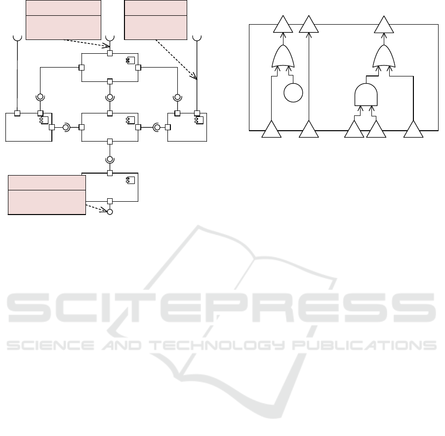
:GPS
Matcher
:GPS
Matcher
:Adequacy
Calculation
:Adequacy
Calculation
:MapClient:MapClient
:Sensor
Matcher
:Sensor
Matcher
:Prediction
AndPlanning
:Prediction
AndPlanning
:~MapTile
Adequacies
:~MapTile
Adequacies
:MapTile
Adequacies
:MapTile
Adequacies
:~Position
Adequacy
:~Position
Adequacy
:~MapLink:~MapLink
:GPS
Data
:GPS
Data
:MapTile:MapTile
:Position
Adequacy
:Position
Adequacy
:~Trajectory:~Trajectory
:~MapLink:~MapLink
:~MapTile:~MapTile :~MapTile:~MapTile
:MapTile:MapTile
:Sensor
Data
:Sensor
Data
:MapLink:MapLink
:MapLink
:MapData:MapData
......
Text = „Crash due to missing
or wrong trajectory“
ASIL = ASIL D
«Hazard»
MissingOrWrongTrajectory
Text = „Crash due to missing
or wrong trajectory“
ASIL = ASIL D
«Hazard»
MissingOrWrongTrajectory
Text = „Tampering with
incoming GPS data“
Category = Tampering
«Threat»
TamperingGPSData
Text = „Tampering with
incoming GPS data“
Category = Tampering
«Threat»
TamperingGPSData
Text = „DoS on incoming
map data“
Category = DenialOfService
«Threat»
DoSonMapData
Text = „DoS on incoming
map data“
Category = DenialOfService
«Threat»
DoSonMapData
Figure 3: Annotated hazard and threats.
architecture by requirements on the behavior of the
software components. These requirements are speci-
fied by means of MSDs (cf. Figure 1). The lifelines of
an MSD represent software components of the static
architecture. The messages between the lifelines are
based on the operations that are defined in the port
interfaces of the components.
The output of this step is the system architecture
with a set of MSDs that specify requirements on the
behavior of its elements. This step is a prerequisite
for our safety and security analysis method. But such
a model-based specification of the architecture and
its behavioral requirements is reasonable for system
development and requirements engineering anyways.
For instance, the MSDs can be used to simulate and
validate the system behavior and to automatically de-
tect inconsistencies (Greenyer et al., 2013).
Annotate Hazards and Threats. In Step 2a, the
safety engineer annotates the static architecture from
Step 1 with hazards. These hazards could origi-
nate from a Hazard Analysis and Risk Assessment
(HARA)(ISO, 2018) that uses the static architecture
as a basis. Each hazard is linked to an output port of a
software component, whose failure causes the hazard.
Figure 3 shows our running example with the an-
notated hazard MissingOrWrongTrajectory. This hazard
expresses a situation in which the Highway Driving
System is active and suddenly stops sending a trajec-
tory or sends a wrong trajectory. This may lead to an
accident if the driver does not recognize and take over
in time.
In Step 2b, the security engineer annotates the
static architecture with threats. These threats could
«SeCFT»
:AdequacyCalculation
SeCFT
v
v
«OR»
«AND»
vv
o
«OR»
:Cr
o
Sensor
MapLink
_senML:V
c
c
GPSMap
Link:C
GPSMap
Link:O
Position
Adequacy:~O
Position
Adequacy:~C
Position
Adequacy
_posA:~V
GPS
MapLink
_gpsML:V
MapTile
Adequacies
_allA:V
Figure 4: SeCFT generated from MSD in Figure 1.
originate from a Threat Analysis and Risk As-
sessment (TARA)(ISO, 2020) applying the STRIDE
method (Shostack, 2014). STRIDE uses a static ar-
chitecture as a basis for analysis and annotates each
identified threat to a software component or connec-
tor, where the threat could manifest in an attack. It
considers six types of threats: spoofing, tampering,
repudiation, information disclosure, Denial of Service
(DoS), and Elevation of Privilege (EoP).
In Figure 3 our running example is annotated with
two threats. The threat TamperingGPSData, which is
associated to the Tampering STRIDE category, de-
scribes that an attacker could manipulate the GPS
data received by the GPS Matcher. The threat DoSon-
MapData, which is associated to the Denial of Service
STRIDE category, describes an attack on the commu-
nication channel to the Map Client such that it no longer
receives MapData.
Generate Failure and Attack Propagation. In
Step 3 of the process, a failure and attack propagation
model is generated for the SoI in form of SeCFTs.
The SeCFTs are automatically derived from the SoI’s
static architecture with annotated hazards and threats,
and its MSD requirements. The SeCFTs follow the
structure of the static architecture. Figure 4 shows
the SeCFT for the component Adequacy Calculation of
our running example. The triangular ports on the
edge represent incoming and outgoing failure modes,
and the internal elements represent gates and a crash
event. The SeCFT generation derives possible fail-
ures and their consequences (i.e., propagation) from
the MSDs. It considers omission (O), commission
(C), value (V), and crash (Cr) failures. Figure 4 shows
failure propagation elements derived from the MSD
shown in Figure 1.
According to the MSD in Figure 1, the Adequacy
Calculation finally shall send the message PositionAd-
equacy. An omission failure (O) would be that this
MODELSWARD 2022 - 10th International Conference on Model-Driven Engineering and Software Development
150
message is not sent as required (it is omitted). This
failure is represented by the outgoing failure mode
PositionAdequacy:∼O in Figure 4. The failure is caused
if the first message of the MSD GPSMapLink is not re-
ceived (omitted) or if the Adequacy Calculation crashes
(Cr) in between. These two causes are derived from
the MSD as the incoming failure mode GPSMapLink:O
and the crash event :Cr that are both connected to the
outgoing omission failure mode via an OR-gate.
A commission failure (C) would occur if a mes-
sage is sent that is not expected. If the first message of
the MSD in Figure 1 GPSMapLink is received although
not expected, the remainder of the MSD would still
be executed. Hence, also the final message would be
sent inadvertently. This failure propagation is repre-
sented by the connected failure modes GPSMapLink:C
and PositionAdequacy:∼C in the SeCFT.
If a message has a parameter, a value failure (V)
would occur if the message is sent with an incorrect
value for that parameter. In Figure 1 all messages
have a parameter. Hence, the SeCFT contains a value
failure mode for each of them. The ValueDependency
in the MSD specifies based on which input parame-
ters the output parameter posA, sent via the message
PositionAdequacy, is calculated. In this case, the pa-
rameter depends on all input parameters. Hence, all
three input value failure modes are connected to the
output failure mode PositionAdequacy posA:∼V. The
AND-gate in the SeCFT is generated based on the
PlausibilityCheck in the MSD. The plausibility check
denotes that the two input values gpsML and senML
are checked for plausibility (e.g., may not deviate too
much). The AND-gate denotes that if only one of
the two parameters has a value failure, the plausibil-
ity check would detect that, and the output value fail-
ure would not occur. Only if both parameters have
a value failure at the same time such that the plausi-
bility check does not fail (e.g., both values are wrong
but do not deviate too much), the output value fail-
ure would occur. All other MSDs are also considered
by the automatic generation, and the SeCFTs are ex-
tended or updated accordingly. Further details on the
failure propagation generation rules can be found in
(Fockel, 2018).
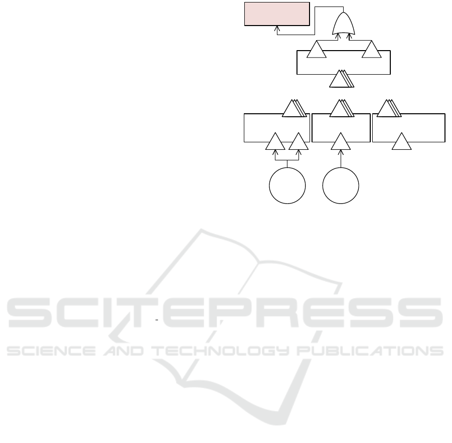
In addition to failures and failure propagations, we
also extend the model by attack events that could lead
to failures and ultimately to the occurrence of a haz-
ard. The attack events are automatically derived from
the threats that were annotated to the static architec-
ture in Step 2b. Figure 5 contains the abbreviated
SeCFT model for the running example. It includes an
event hazardEvent representing the occurrence of the
hazard annotated in Figure 3 and two attack events
derived from the threats in that figure.
«SeCFT»
:SensorMatcherSeCFT
«SeCFT»
:PredictionAndPlanningSeCFT
vo
«Event»
hazardEvent:Missing
OrWrongTrajectory
«OR»
Trajectory:~O Trajectory_t:~V
«SeCFT»
:MapClientSeCFT
«SeCFT»
:GPSMatcherSeCFT
ocv v
:DoSon
MapData
:Tampering
GPSData
MapData:O
GPS
Data:C
GPS
Data_d:V
SensorData_d:V
...
Figure 5: Hazard and attack events based on Figure 3.
The SeCFT model contains SeCFTs for each com-
ponent that is found in the static architecture together
with their failure propagation elements. Following
the structure of the static architecture, the Adequacy-
CalculationSeCFT, shown in detail in Figure 4, is lo-
cated centrally in the model. Failures received from
the SeCFTs GPSMatcher, MapClient, and SensorMatcher
propagate through the failure modes of AdequacyCal-
culationSeCFT to PredictionAndPlanningSeCFT and even-
tually may lead to the hazard MissingOrWrongTrajectory.
Attack events are generated into the SeCFT based
on the architectural element that the corresponding
threat is annotated to, and based on the threat’s
STRIDE category. We consider threats to be either
annotated to a connector or to a component. If a
threat is annotated to a component, a corresponding
attack event is generated into the SeCFT that repre-
sents the failure propagation of that component and it
is connected to output failure modes of that SeCFT. If
a threat is annotated to a connector, a corresponding
attack event is generated into the parent SeCFT such
that the attack event can be connected to input fail-
ure modes of the SeCFT representing the connector’s
target component.
The threat TamperingGPSData is annotated to a
connector leading to the component GPSMatcher (cf.
Figure 3). Hence, in Figure 5, the attack event :Tam-
peringGPSData was generated on the top hierarchy
level and connected to input failure modes of the
SeCFT GPSMatcherSeCFT. Analogously, the attack
event :DoSonMapData was generated and connected to
an input failure mode of the SeCFT representing the
failure propagation of the component MapClient.
Table 1 lists the generation rules for the connec-
tions from generated attack events to failure modes of
Semi-automatic Integrated Safety and Security Analysis for Automotive Systems
151

the SeCFTs. Based on the STRIDE category of the
corresponding threat, an attack event is connected to
failure modes of different types. In general, we do not
automatically connect attack events of threat category
Repudiation or Information Disclosure. We consider
these categories of threats to not have direct influence
on safety. Merely, such attacks might be performed
to prepare a following attack that does have direct in-
fluence on safety. In our approach, those threats (of
differing threat category) should be annotated in the
architecture instead.
For threats that are annotated to a connector, we
consider the two STRIDE categories Tampering and
Denial of Service. As tampering attacks on a connec-
tor, we assume two cases: (1) A malicious change of
transmitted information (e.g., Man-in-the-Middle at-
tack) leading to an input value failure, and (2) sending
valid information when not expected (e.g., replay at-
tack) leading to an input commission failure. In Fig-
ure 5, the attack event :TamperingGPSData is linked to
the value failure mode GPSData d:V, representing the
malicious change of GPS data, and to the commission
failure mode GPSData:C, representing the sending of
GPS data when not expected by the GPS Matcher.
A DoS attack on a connector would lead to in-
formation not reaching its destination, hence, to an
input omission failure. In Figure 5, the attack event
:DoSonMapData is linked to the omission failure mode
MapData:O, representing the omission of map data ex-
pected by the Map Client due to the DoS attack on the
connector that transmits the map data.
For connectors, the automatic generation does
not consider repudiation and information disclosure
threats as explained above. In addition, we also do
not consider Spoofing and EoP threats on connectors.
In our view on spoofing, not the id of the sent infor-
mation is taken over but the id of the sender of that
information. Hence, the threat should be annotated to
the sending component. Similarly, higher privileges
might be gained by sending a certain message, but the
privileges are checked by the receiving component.
Hence, in our approach, also EoP threats have to be
annotated to components.
For threats that are annotated to a component, we
consider all STRIDE categories except Repudiation
and Information Disclosure as explained above. If
an attack spoofs a component, tampers with it, or
gains higher privileges on it, we consider this attack
to stop outgoing information from being sent (omis-
sion), to send unexpected information (commission),
or to change outgoing information (value failure).
Hence, we connect such an attack event to all outgo-
ing failure modes of the three types O, C, and V. Sim-
ilarly, if a DoS attack is performed on a component,
Table 1: Rules for connecting attack events to failure
modes.
Threat Target failure mode types if threat on
category connector component
S - ∼O, ∼C, ∼V
T V, C ∼O, ∼C, ∼V
D O ∼O
E - ∼O, ∼C, ∼V
we consider this attack to stop all outgoing informa-
tion. Hence, we connect such an attack event to all
outgoing O failure modes of the component’s SeCFT.
The final SeCFT model describes failure propa-
gation paths through the architecture. These paths
start from attack events, crash events, or input fail-
ure modes and lead to hazard events or output failure
modes that are not connected to a hazard. The paths
can merge via OR- and AND-gates (cf. Figure 4).
Analyze Safety and Security Intersections. In
Step 4, the engineers analyze the SeCFT to find safety
and security issues in the current architecture and its
required behavior. This analysis is supported by an
automatic identification of critical paths and calcula-
tion of MCSs. The focus lies on the interplay of safety
and security measures, e.g., the effect that security at-
tacks on the SoI might have on its safety.
The automated analysis starts from each hazard
and additionally from each threat. Starting from a
hazard, the SeCFT is used to identify (1) by what
failures and threats it could be caused (hazard criti-
cal paths) and (2) which failures and threats have to
occur simultaneously for the hazard to occur (MCSs).
Starting from a threat, the SeCFT is used to identify
what failures and hazards it might cause (threat criti-
cal paths).
Critical paths show possible failure propagations
through the SoI but give no answer to what failures
and attacks have to occur simultaneously for a hazard
to occur. This information is encoded in MCSs. They
specify which events have to occur simultaneously:
Only if all events of a MCS occur simultaneously the
corresponding hazard is caused.
The automated analysis calculated two MCSs for
the running example:
MCS
1
= {:TamperingGPSData, SensorData d:V}
and MCS
2
= {:DoSonMapData}. MCS
1
contains the
attack event :TamperingGPSData and the failure mode
SensorData d:V also shown in Figure 5. This MCS
describes that if the tampering attack on the GPS
data and a value failure of the sensor data received
by the Sensor Matcher occur together, this will result
in the hazard. Individually, these two events will
not lead to the hazard to occur. MCS
2
only contains
one element, the attack event :DoSonMapData from
Figure 5. This MCS describes that if the DoS attack
MODELSWARD 2022 - 10th International Conference on Model-Driven Engineering and Software Development
152

on the map data occurs, this will immediately lead
to the hazard to occur, no other attack or failure is
required to occur as well.
To reduce risk, the engineers may want to remove
a MCS (e.g., remove a failure source) or at least add
further elements to it (e.g., increase redundancy). For
that, they need to understand why it exists, i.e., from
what parts of the architecture and requirements its el-
ements originate. To support that, our approach au-
tomatically determines the critical paths through the
SeCFT model and generates trace links, that allow
to navigate from each element in the SeCFT model
to the elements in the architecture and MSD require-
ments that they originate from.
The critical path starting from the attack event
:TamperingGPSData of MCS
1
and leading to the haz-
ard, follows the SeCFT model denoted in Figures 5
and 4. It reads as follows: :TamperingGPSData → GPS-
MatcherSeCFT::GPSData d:V → . . . → AdequacyCalcula-
tionSeCFT::GPSMapLink gpsML:V → Ade...SeCFT::AND
→ . . . → Ade...SeCFT::PositionAdequacy posA:∼V →
. . . → PredictionAndPlanningSeCFT::Trajectory t:∼V →
hazardEvent:MissingOrWrongTrajectory. The AND-gate
inside AdequacyCalculationSeCFT on this path is traced
to the plausibility check in the MSD from Figure 1.
It is also on the critical path starting from the sensor
data value failure mode of MCS
1
. Hence, it shows
that the intention of the plausibility check works: the
two ways of identifying the vehicle’s position on the
map via GPS and via vehicle sensors are redundant
concerning value failures, even if they are caused by
a tampering attack.
5 EVALUATION
To evaluate the approach presented in Section 4, we
perform a case study inspired by the guidelines de-
fined in (Kitchenham et al., 1995). The case study is
performed on realistic examples of assistance systems
from the automotive industry.
The objective of this case study is to evaluate if the
presented approach produces correct and complete re-
sults for real-world safety-critical systems. With the
help of the presented method, safety and security as-
pects of components shall be identified and consid-
ered simultaneously. Our approach shall thereby en-
able the engineers to identify critical paths from at-
tacks to hazards in the communication between com-
ponents, and represent attacks and failure modes in
a common MCS. We can summarize this objective in
the following evaluation question:
Does the automated application of the presented
method produce correct and complete results that al-
low to identify correlations between safety and secu-
rity measures early in the development of the system?
To answer this evaluation question, we conduct
our case study on two sample cases. The first case is
the running example we presented in Section 3, that
is used throughout this paper. The actual modeled ex-
ample consists of 377 model elements, including 9
components and 17 MSDs. This running example is a
simplified version of a larger, more complex system.
We use this larger model for the second case of our
case study. The second case is a real-world example
of an SAE level 3 (SAE, 2021) assistance system con-
sisting of 1025 model elements. This model includes
19 components and 43 MSDs. We consider both cases
as realistic examples since they refer to a system that
is actively developed in the automotive industry.
Conducting the Case Study. To conduct the case
study, we implemented software components as plug-
ins for the Eclipse IDE. We used the Eclipse Papyrus
1
UML/SysML framework to specify the static archi-
tecture and MSDs for the two cases as presented in
Section 4. Specifying these models in Papyrus fur-
ther allows us to define verification rules in the Ob-
ject Constraint Language (OCL) and evaluate them
automatically using the model validation feature of
Papyrus. The SeCFT generation and the analysis of
safety and security intersections are realized as two
separate QVTo
2
model-to-model transformations.
We executed the QVTo transformation code using
the Eclipse platform in version 2021-06. On a typical
business workstation, the transformation completed
successfully with a total execution time of 3.683 sec.
Analyzing the Results. As a result of the safety and
security intersection analysis, our prototypical imple-
mentation created 83 critical paths for Case 1 and 171
critical paths for Case 2. Additionally, the implemen-
tation calculated 6 MCSs for Case 1 and 12 MCSs
for Case 2. We shared these generated results with
experts from the application domain, which deemed
the the results of our transformation to be correct and
complete. By identifying correct and complete crit-
ical paths and MCSs in the communication between
components of our two cases, we rate our correspond-
ing evaluation question as fulfilled.
Threats to Validity. A potential threat to the con-
struct validity is that the case study was designed and
conducted by the same researchers. The researchers
may therefore have a bias towards the developed ap-
proach. To mitigate this threat, the prototypical im-
plementation was developed by another researcher
than the researchers that developed the methodology.
1
https://www.eclipse.org/papyrus
2
https://www.eclipse.org/mmt/qvto
Semi-automatic Integrated Safety and Security Analysis for Automotive Systems
153

Additionally, the results generated by the prototypical
implementation were evaluated with experts from the
automotive domain.
Concerning the generalizability of the case study
results, a threat is that the number of cases used in
this case study might be too small and the selected
cases might not be representative for the application
domain. To mitigate this threat, the cases were devel-
oped in cooperation with experts from the automotive
industry and are derived from an actual level 3 assis-
tance system.
6 CONCLUSION
In this paper, we introduce a method for the integrated
consideration of safety and security in early phases of
the system design. We evaluate our method on a level
3 assistance system called Highway Driving System.
The method focuses on an architectural level of sys-
tem development and builds upon existing analysis
methods of the safety and security domains, namely
FTA, STRIDE, and attack trees. At its very core, our
4-step method identifies for each attack which haz-
ards it may trigger and for each hazard which com-
binations of attacks and other faults it can be caused
by. This process is automated by our tooling to a large
extend.
Our approach supports the safety and security en-
gineers in a way such that security aspects can be
leveraged in the context of considering safety. In
more concrete terms, it helps to identify the impact
attacks can have on the safety of the vehicle via the
identification of hazards triggered by a certain attack.
Additionally, it helps to identify the influence safety
aspects have on security. Finally, the iterative na-
ture of the method ensures that the safety impact of
newly introduced security controls becomes apparent
in each following iteration.
In future work, the approach could be extended
to automatically propagate ASILs of hazards through
the SeCFT. This ASIL propagation would automati-
cally respect the ASIL tailoring rules defined in (ISO,
2018) and annotate ASILs to system components,
MSD requirements, and threats.
REFERENCES
Fockel, M. (2016). ASIL tailoring on functional safety re-
quirements. In Skavhaug, A., Guiochet, J., Schoitsch,
E., and Bitsch, F., editors, 5th International Work-
shop on Next Generation of System Assurance Ap-
proaches for Safety-Critical Systems (SASSUR), vol-
ume 9923 of LNCS. Springer International Publishing.
Co-located with SAFECOMP 2016.
Fockel, M. (2018). Safety Requirements Engineering for
Early SIL Tailoring. PhD thesis, Paderborn Univer-
sity.
Greenyer, J., Brenner, C., Cordy, M., Heymans, P., and
Gressi, E. (2013). Incrementally synthesizing con-
trollers from scenario-based product line specifica-
tions. In 9th Joint Meeting of the ESEC/FSE.
Harel, D. and Maoz, S. (2008). Assert and negate revisited:
Modal semantics for uml sequence diagrams. Soft-
ware & Systems Modeling, 7(2):237–252.
Holtmann, J. and Meyer, M. (2013). Play-out for hierarchi-
cal component architectures. In 11th Workshop on Au-
tomotive Software Engineering, volume P-220 of GI-
Edition – LNI. Koellen.
IEC (2003). IEC 60300-3-1: Dependability management –
Part 3-1: Application guide.
IEC (2006a). IEC 60812: Analysis techniques for system
reliability – Procedure for FMEA.
IEC (2006b). IEC 61025: Fault tree analysis (FTA).
ISO (2018). ISO 26262: Road vehicles – Functional safety.
ISO (2020). ISO DIS 21434: Road vehicles – Cybersecurity
engineering.
Kaiser, B., Liggesmeyer, P., and M
¨
ackel, O. (2003). A new
component concept for fault trees. In 8th Australian
workshop on Safety critical systems and software.
Kitchenham, B., Pickard, L., and Pfleeger, S. (1995). Case
studies for method and tool evaluation. IEEE Soft-
ware, 12(4):52–62.
Lisova, E.,
ˇ
Sljivo, I., and
ˇ
Cau
ˇ
sevi
´
c, A. (2019). Safety and
security co-analyses: A systematic literature review.
IEEE Systems Journal, 13(3):2189–2200.
Macher, G., Sporer, H., Berlach, R., Armengaud, E., and
Kreiner, C. (2015). SAHARA: A security-aware
hazard and risk analysis method. In 2015 Design,
Automation Test in Europe Conference Exhibition
(DATE).
Ruijters, E., Schivo, S., Stoelinga, M., and Rensink, A.
(2017). Uniform analysis of fault trees through model
transformations. In 2017 Annual Reliability and
Maintainability Symposium (RAMS), pages 1–7.
SAE (2021). SAE J3016: Taxonomy and Definitions for
Terms Related to Driving Automation Systems for On-
Road Motor Vehicles.
Schmittner, C., Gruber, T., Puschner, P., and Schoitsch, E.
(2014). Security application of failure mode and ef-
fect analysis (FMEA). In Bondavalli, A. and Di Gi-
andomenico, F., editors, Computer Safety, Reliability,
and Security (SAFECOMP 2014).
Schneier, B. (1999). Attack trees. Dr. Dobb´s journal,
24(12):21–29.
Shostack, A. (2014). Threat modeling: Designing for secu-
rity. John Wiley & Sons.
Sommer, F., D
¨
urrwang, J., and Kriesten, R. (2019). Sur-
vey and classification of automotive security attacks.
Information, 10(4):148.
Steiner, M. (2016). Integrating Security Concerns into
Safety Analysis of Embedded Systems Using Compo-
nent Fault Trees. PhD thesis, TU Kaiserslautern.
Steiner, M. and Liggesmeyer, P. (2015). Qualitative and
quantitative analysis of CFTs taking security causes
into account. In Computer Safety, Reliability, and Se-
curity (SAFECOMP 2015).
MODELSWARD 2022 - 10th International Conference on Model-Driven Engineering and Software Development
154
