
Transforming Domain Specific Modeling Languages into Feature Models
Maouaheb Belarbi and Vincent Englebert
NADI Research Institute, University of Namur, Belgium
Keywords:
Product Line, DSML, Feature Model, Variability, Software Factory, Transformation.
Abstract:
This paper proposes a methodology for software factory design guided by DSMLs (Domain Specific Modeling
Languages) in the context of the SPL (Software Product Line) area. In order to guide the engineer in the design
of the generative process, we propose a transformation allowing to transform the annotated metamodel of a
DSML into an Feature Model that can be used later as a decision tree to help the engineer in the choice of the
best implementation tactics for the variants. The article presents and illustrates the transformation based on an
industrial example.
1 INTRODUCTION
A Software Product Line (SPL) covers the feasible
space of all possible software products for a given do-
main of interest (White et al., 2008). In other words,
it provides the means for capturing the commonal-
ities and addresses variability by presenting the set
of dissimilarities between the products. In this con-
text, Feature Model (FM) is the most popular nota-
tion for modeling features as configurable units. It
helps developers to keep an overall understanding of
the system. Besides, FM supports development, vari-
ant derivation, and configuration activities that sustain
the system’s long-term success. Model Driven Engi-
neering proposes to define Domain Specific Modeling
Languages (DSML) in order to capture the needs of
systems of the same family through a modeling lan-
guage dedicated to the family, which is then called the
domain. While FM Languages offer adequate models
for analysis and code generation, they are limited to a
taxonomic vision of features in a tree-like form com-
pleted by constraints (Schobbens et al., 2006). The
DSML approach proposes metamodels that can free
themselves from this by offering a more unencum-
bered description but which does not, a priori, offer
easy reading for code generation.
This article proposes to combine the two ap-
proaches in order to combine their advantages and
mitigate their weaknesses. In this context, our objec-
tive is to propose a methodology for building software
factories using a DSML for domain description taking
advantage of their expressiveness and then deriving an
FM that offers a more oriented reading for code gen-
eration and verification of acceptable configurations.
In this article, we present a transformation sys-
tem to convert a DSML meta-model into an FM.
The transformation takes as input an annotated
DSML metamodel and produces the corresponding
FM objects enriched with different information types
namely cardinality, attributes, and constraints. Anno-
tations are used to make explicit which information
in the DSML metamodel denotes features as well as
a direction for the traversal path in order to extract a
tree view from a graph, although it not necessarily a
tree view. The resulting FM formalism is not origi-
nal, but we generate from the DSML an FM in XML
format that can be imported into third-party tools and
later used as a decision tree to support thinking for a
generative code strategy.
The rest of the paper is organized as follows:
Section 2 defends the preliminaries motivation be-
hind the proposal and demonstrates a real industrial
project as a running example. In section 3, we present
an overview of the Methodology Software Factory
framework proposed in the context of the current the-
sis project. Section 4 is carried out to introduce the
transformation system as the main contribution of the
present paper and primary stage in our global method-
ological framework. Some potential weakness threat-
ening our proposal are identified in the section 5 with
some attempts to mitigate them. Finally, some of the
relevant related work are presented in section 6 fol-
lowed by a conclusion and some of our perspectives
in section 7.
Belarbi, M. and Englebert, V.
Transforming Domain Specific Modeling Languages into Feature Models.
DOI: 10.5220/0010772000003119
In Proceedings of the 10th International Conference on Model-Driven Engineering and Software Development (MODELSWARD 2022), pages 137-146
ISBN: 978-989-758-550-0; ISSN: 2184-4348
Copyright
c
2022 by SCITEPRESS – Science and Technology Publications, Lda. All rights reserved
137

2 MOTIVATION AND RUNNING
EXAMPLE
This section argues the appeal for transforming
DSML metamodel to FM which, at the best of our
knowledge, has not been tackled before. A running
example is presented to illustrate the transformation
steps throughout the paper.
2.1 Running Example: Insurance
System
The present running example describes a real world
case study, which was developed in the context of
an industrial project: an insurance portfolio offers
protection against a specified type of risk to a col-
lection of policyholders. Fig 1 resumes the domain
metamodel proposed in (Kelly and Tolvanen, 2008).
The latter specifies all knowledge of insurance prod-
ucts. This schema contains annotations in notes that
will be explained later. Product bundle concept de-
scribes the Insurance Systems portfolio where Several
Product instances define different application vari-
ants. Each Elementary Product consists of defin-
ing EP Cover and EP tariff concepts. In fact, EP
Cover defines the risk to be insured for an individual
or an entity. Whereas, EP tariff concept designates
the amount that customers must pay for insurance ser-
vice subscription. Besides, Risk introduces peril that
can threaten the safety of the Insured Object and
can arise from any fortuitous cause which is either an
Event, a Damage, or a Danger. Coverage services
protect different Insured Object types: simple par-
ties such that Elementary Insured Object or com-
pound elements like Composite Insured Object.
Finally, when encountering a risk customers are re-
imbursed and receive a Payment as a financial com-
pensation according to the typeOfPayment attribute.
For comprehensive investigation the initial deci-
sion entailed the selection of Insurance System case
to represent the later PL due to several reasons: In
fact, real industry case applications raise the domain
real relevant challenges. Hence, they present a way
to check the usability and credibility of our approach
when it crashes into reality. In addition, the case study
is relevant for FM context since (i) several variability
points are related to heterogeneous concepts of insur-
ance systems and (ii) many alternative and optional
functionality exist.
2.2 Motivation
Leveraging DSML metamodels for designing domain
portfolio allows managing problem space and resolv-
ing its variability in a complete way. In Fig 2, the flow
in the highest part describes PL by a domain model
upon which code generators basically create the com-
ponent instances required for assembling a specific
product.
However, despite the inroads that MDE has made
in industry, code generators are often seen as black-
boxes since engineers are weakly involved during
software variants derivation (Harrand et al., 2016).
Consequently, recurring complaints and obstacles can
be cited according to: (i) selecting concepts partici-
pating in a specific product and neglecting others; (ii)
viewing hierarchically the whole set of system func-
tionality; and finally (iii) generating the code assets
with different realization techniques each one is suit-
able for specific feature set requirements.
To overcome these problems, we propose to de-
sign the domain space with a DSML metamodel and
to transform it into FM as an intermediate phase be-
fore product engineering – our contribution is pre-
sented in the lower part of Fig reffig:motivation. Our
Software Factory takes as input the obtained FM and
produces software code assets according to differ-
ent programming techniques. These were chosen to
satisfy the engineer requirements and the variability
types that will be explained in this section.
The result of the transformation is a FM enriched
with additional concepts (White et al., 2008) retrieved
from the DSML: (i) cardinalities to specify the num-
ber of occurrences for the solitary subfeature, (ii) at-
tributes, and (iii) constraints that must be adhered
when selecting variant in parent-child and cross-tree
relationships.
The obtained FM provides a support on which
the engineer can specify for each variation point fol-
lowing variability types cited in (Tërnava and Collet,
2017):
• Binding-time. Variabilities are instantiated and
bound to a variant at a certain point of time:
Mechanisms with early binding time such that the
construction time potentially optimize running ef-
ficiency. However, mechanisms with late binding
time such that the runtime provide more flexibility
and support dynamic system adaptations.
• Granularity. A variation point or variant in
the core-code assets can have different sizes: a
coarse-grained element such that, file, package,
class, interface; a medium-grained granularity
e.g., a method, a field inside a class; or a fine-
grained element e.g., an expression, statement, or
block of code.
• Evolution. Essentially, closed variation requires
that the variable code is compiled together with
MODELSWARD 2022 - 10th International Conference on Model-Driven Engineering and Software Development
138
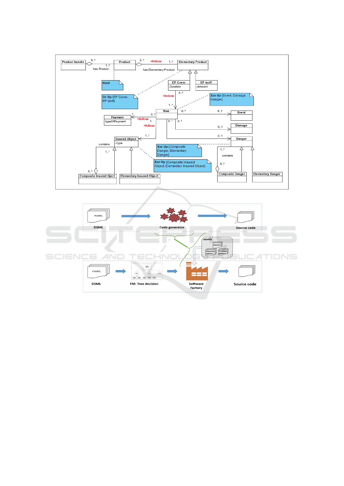
Figure 1: DSML metamodel of Insurance System.
Figure 2: Generating software products: difference between literature and present contribution.
the core code, thus, no new variants can be added
independently. However, open variability enables
the external developers to provide modules (plug-
ins, etc.)with their own code after its compilation.
• Quality Criteria. several important criteria can
be considered such that: Separation of Concerns,
Scalability, Traceability, etc.
Fig. 7 is an excerpt of FM enriched with the set
of attributes and cardinality retrieved for each fea-
ture from DSML. Different configurations could be
planned when considering different values for the at-
tributes of the same feature. For example, consider-
ing typeOfPayment attribute of the feature Payment
such that bank transfer or with Mastercard payment
implies a different application behavior. Hence, the
obtained result ensures rich semantic FM capabili-
ties since it extends the FM basic skeleton with car-
dinality, attribute types, and constraints in the same
formalism. The goal of this FM is to be used later
as a decision tree to guide the generative process of
our software factory: the engineer annotates the vari-
ation points with aforementioned variability types.
Therefore, a possible useful variability mechanisms
could be employed to implement the product fam-
ilies. For example, deciding that feature Risk is
set up at runtime with fined-grained elements favors
Conditional Execution mechanism which entails
high flexibility to adapt the system but also a limited
. However, considering that feature Payment is re-
solved at Compile-Time this implies it can be real-
ized at code level by Aspect-oriented mechanism
which entails a good definition for this feature. Con-
Transforming Domain Specific Modeling Languages into Feature Models
139

sidering the overall engineer requirements defined for
each variation point, the framework can then deter-
mine the possible generative strategies that could be
entrusted to satisfy them and produce the guidelines
to implement them.
To sum up, we propose to perform PL domain
analysis with DSML metamodel to obtain a high level
of expressiveness. Thereafter, before tackling the
products derivation process, we go through an inter-
mediate phase in which engineers can select some
features, neglect others, annotate the variation point,
etc, based upon the FM considered here as a decision
tree. This phase, involves the engineers in all the soft-
ware life-cycle and allows to generate assets in dif-
ferent programming techniques. Finally, considering
the enriched semantic of FM retrieved from DSML
and the tree structure of this formalism, engineers ob-
tain an easy and understandable display of the whole
system functionality. Consequently and for the all the
reasons above, we assume that transforming DSML
into a FM is worth investment in the context of our
proposed methodological framework.
3 OVERVIEW OF THE
PROPOSED METHODOLOGY
SOFTWARE FACTORY
We propose a methodology to design software fac-
tories that cover a large number of generation code
strategies to derive product variants. Our previous re-
search have led to the framework (Belarbi and Engle-
bert, 2019) depicted in Fig. 3 and decomposed into
three levels:
1. Meta-metamodel layer (M3);
2. The engineer metamodel layer (M2) is meant to
setup the product line;
3. The client model layer (M1) is meant to customize
the product.
The Methodology Software Factory performs as fol-
lows: once the PL is defined, the generative strategies
are determined. Here, the engineer chooses a useful
strategy to derive the product and the methodological
framework will generate the guidelines to implement
it.
Pseudo-phase 1: Extending the
Meta-metamodel
The meta-metamodel situated at the highest level of
abstraction is inspired by the Meta Object Facility
(MOF) standard. Additional attributes are added to
identify specific elements in the DSML metamodel
and to guide their transformation to the right concepts
of FM. These additional information were proposed
based upon FM metamodel (Perrouin et al., 2008)
which presents basic existing concepts. We suppose
that the DSML metamodel contains concepts whose
semantics are close to FM features. In other words,
DSML metamodel would have a class for the root
feature. Starting from this last, the engineer speci-
fies classes in the DSML metamodel that must exist
in the future FM, their group set type, and the con-
straints within. Thus, we added the sky blue back-
ground attributes to Attribute, Class, and Associa-
tionEnd classes as shown in top of Fig. 3 shown later
inside notes
1
attached to classes of the DSML meta-
model.
• A Class whose attribute Class.root is true de-
notes the root node of the FM which must be
unique. The transformation process will start
from this.
• When the attribute Class.variationPoint is
set to true, the corresponding class denotes a
variation point whose features are constrained by
one of these logical operators: or, and, and xor.
• Attribute class whose added
isExtractedAsFeature attribute is set to
true, implies that it is reified as a feature during
the transformation process.
• AssociationEnd class contains the boolean at-
tribute follow. When it is set to true, this points
the way from a class considered as a future fea-
ture to a nearby class that must be considered as a
refinement of the first-one.
• Classes Constraint and Constrained with
the operands association gather potential fea-
tures together in constraints whose type is
typeConstraint (requires,mutex).
We called this step as a pseudo-phase since it is
made only once and is just a prerequisite for the other
phases.
Phase 2: Defining the Product Line
The domain engineer specifies the DSML metamodel
elements with adequate complementary information
mentioned earlier: root class, the constraints, and
the group sets. Since the expressiveness of a DSML
and FM may not be perfectly aligned, the consid-
ered transformation is here just a best-effort to trans-
late a DSML into the best FM that approximates the
1
The use of stereotypes would have been a bet-
ter solution. Unfortunately, their visualization on
AssociationEnds is not supported by all CASE tools.
MODELSWARD 2022 - 10th International Conference on Model-Driven Engineering and Software Development
140
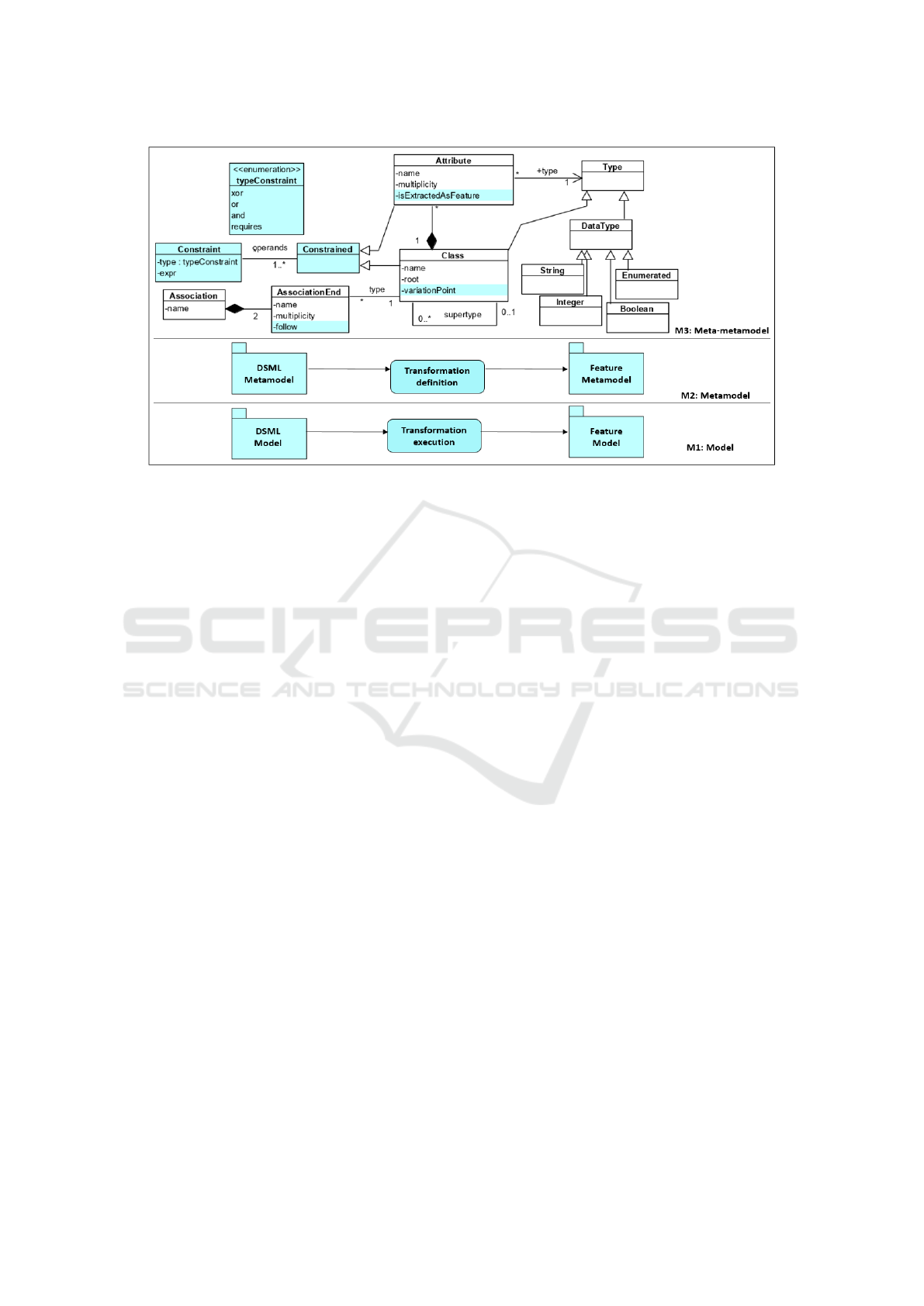
Figure 3: Overview Methodology Software Factory framework.
features represented by the DSML. In the Insurance
System metamodel (Fig 1), Insured Object (resp.
Danger) are designed with the composite design pat-
tern. That cyclic information will be pruned in the
FM since the contains associations are not marked
as followed. It is up to the engineer to check the con-
sequences and make corrections if necessary either in
the DSML metamodel or in the FM. The obtained FM
will be used later as a decision tree to guide the gen-
erative process of our proposed software factory.
Phase 3: The Product Configuration
The lowest layer of the framework characterizes the
application engineering in which the product owner
uses the DSML to define his requirements in a DSML
model transformed to a specific FM setup. No specific
effort from the engineer is required at this moment.
He just defines with this model the desired functional-
ities the product owner intends to offer to customers.
This model will be later transformed into a configu-
ration of the FM generated from the previous phase.
Since the two under-most layers of the framework in-
volve the transformation of DSML to FM we tackle
the following section.
4 TRANSFORMATION SYSTEM
This article focuses on phase 2 of the methodology to
setup the product line. We suppose that the pseudo-
phase has been fulfilled beforehand. According to
the framework M2 level, the engineer overrides the
DSML metamodel default value of the attributes men-
tioned earlier and will be then transformed to a FM.
In the literature, many researchers argue that writ-
ing transformations using specific transformation lan-
guages seems to be impractical (Burgueño and Cabot,
2019) and they prefer using general purpose lan-
guages. The same reasons led us to use Java: it pro-
vides an efficient way to define and manipulate at the
same time both metamodels and models later. Be-
sides, new applications could be incorporated fluently
in the program since models and their metamodels
exist as Java constructs. Before opting for a final
technology we needed to experiment that adding the
aforementioned attributes to the meta-metamodel can
be entrusted to ensure the transformation of DSML
to FM. To this purpose, we built a prototype for the
transformation system presented in Fig. 4 which per-
forms as follows:
– Step 1 The first step consists in annotating manu-
ally the DSML metamodel according to the extended
meta-metamodel inside any compliant tool. The rest
of transformation steps are launched automatically
and successively.
– Step 2 Java source code is generated from this meta-
model. Meta-elements (classes, attributes, associa-
tions,etc) are transformed into Java artifacts. Anno-
tations are preserved and transformed into Java anno-
tations.
– Step 3 DSML classes and elements are retrieved
dynamically, their annotations are explored in order
to transform them to the right FM concepts. Then,
relations and constraints will be established between
the created nodes. Its execution produces new Java
objects that denote the FM metamodel.
– Step 4 is called by step 3 to marshal FM Java ob-
Transforming Domain Specific Modeling Languages into Feature Models
141
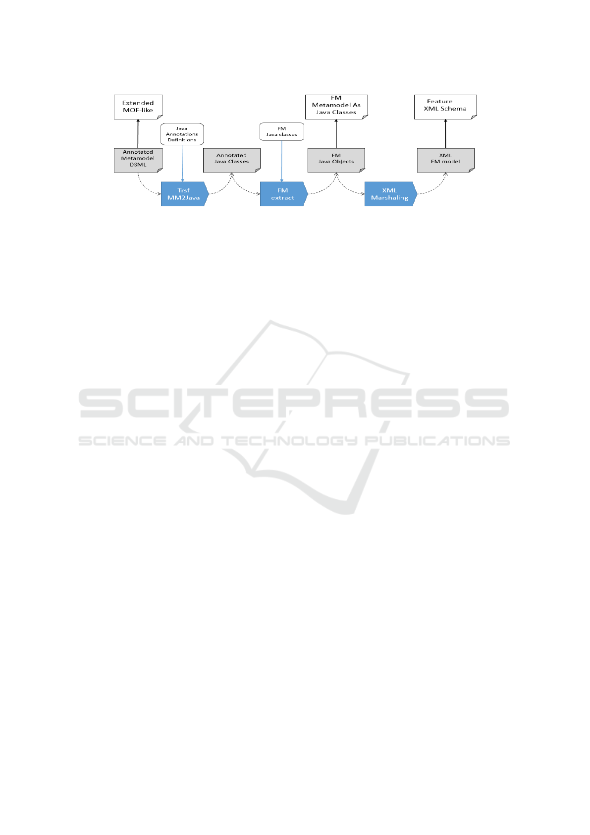
Figure 4: Overview of the global transformation system architecture.
jects to XML objects compliant to our proposed fea-
ture language. Starting with step 2 as input, the rest
of the transformation is launched automatically in a
transparent way.
4.1 Step 1 - Transforming DSML
Metamodels to Java Code Source
The first phase consists in generating the Java code
from the DSML metamodel by preserving the annota-
tions. We suppose here that metamodels are designed
with UML class diagrams and the generation process
is inspired by the transformation rules (Klare et al.,
2016). The transformation insures that semantics is
preserved.
• Each class is transformed to a Java class with the
same attributes and associations.
• One-to-one associations between classes C
1
and
C
2
are implemented by adding an attribute in C
1
typed as C
2
and an attribute in C
2
typed as C
1
.
• A one-to-many association from class C
1
to C
2
is transformed by inserting a Java collection in
C
1
typed as C
2
and a new inverse attribute in C
2
typed as C
1
. The Risk class of the example has
many Insured Object is transformed by insert-
ing a collection of type Insured Object and an
attribute typed as Risk in respectively Risk and
Insured Object classes.
• A many-to-many association between classes C
1
to C
2
is implemented with Java collections in both
classes. Product and Elementary Product are
described in code by collection in both corre-
sponding classes.
• Generalization relationships are mapped to ex-
tends relations between respective classes. While,
Aggregation and Composition relationships are
converted by adding in the parent class C
1
an at-
tribute of type C
2
. Several Insured Object in-
stances, in the example, are part of Composite
Insured Object with many-to-many multiplic-
ity. The transformation inserts a collection of
type Insured Object in Composite Insured
Object and vice versa.
The presence of reverse attributes on each side
introduces redundant information but will help the
transformation process, since all the information is
present in all classes.
On the first hand, the method provides a Java
translation of the FM metamodel depicted in Fig. 5.
It sums up basic concepts of all existing FM versions:
The Feature class contains a list of edges (class
Edge) linking features together with the child and
parent association. A Feature Model has only one
root and possible several features grouped together
with an operator (class Operator) such that Or, Xor,
and And. Finally, the presence of feature in the model
can appeal a requirement (class ConstraintEdge) re-
lated to another. The Java classes have been generated
according to the earlier rules. These classes will be
later instantiated by the transformation to store the re-
sulting FM.
On the second hand, we transform similarly the
DSML metamodel concepts to Java classes. In ad-
dition, the value of the meta-attributes mentioned in
section 3 (i.e, root, feature, variation-point) and edited
manually by the engineer in the DSML metamodel
are converted and preserved in Java annotations:
• The transformation begins by looking for the
class with a meta-attribute Class.root set to
true.It is translated to a @Root annotation at-
tached to the resp. Java class. By this reason-
ing, the Product class is annotated as @Root.
The transformation starts then its traversal by
following associations whose ends have a meta-
attribute AssociationEnd.follow set to true
with a depth-first strategy. It continues on other
paths until no more classes must be investigated.
Since FM is a direct acyclic graph, the traversal
rolls back when the transformation encounters a
class that has already been mapped and a warning
is displayed to attract attention.
• When AssociationEnd.follow is worth true,
MODELSWARD 2022 - 10th International Conference on Model-Driven Engineering and Software Development
142
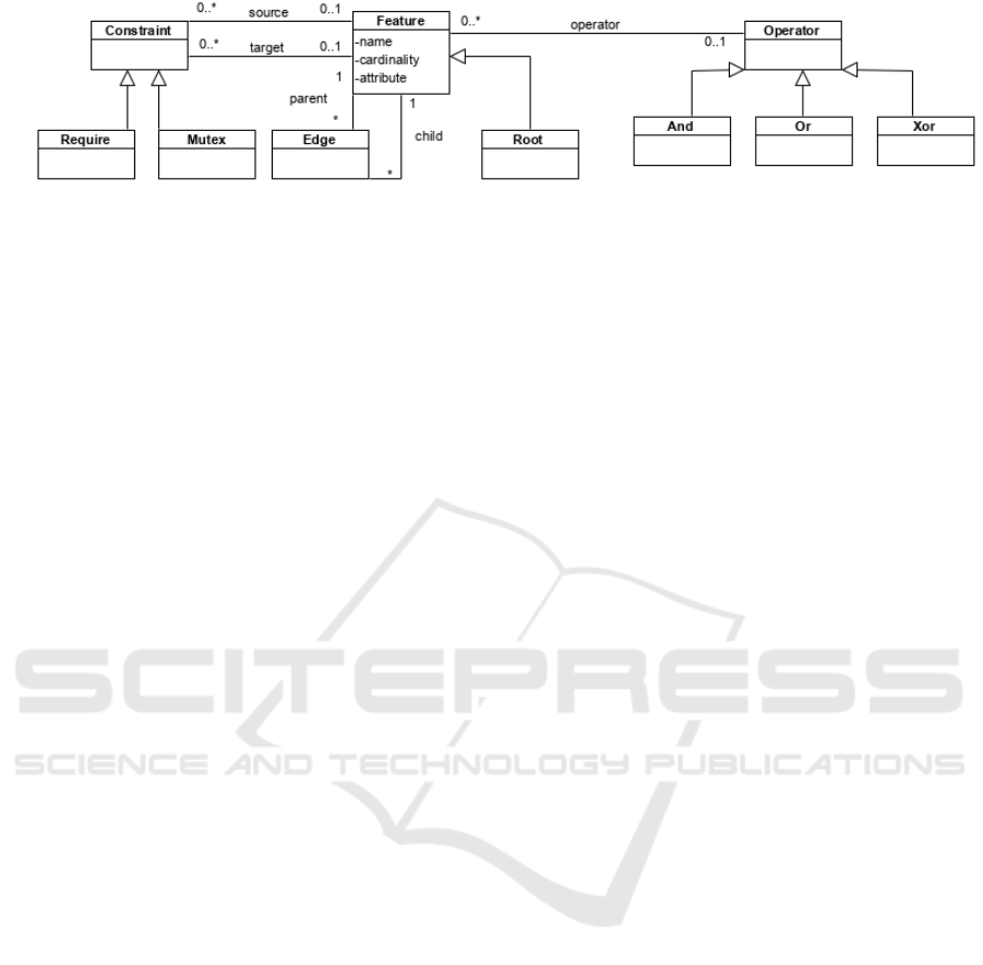
Figure 5: Feature Metamodel.
the @Feature annotation is added to the class on
this side of the association end and the @ChildOf
annotation is added to the attribute that imple-
ments this association. Elementary Product
class contains an AssociationEnd.follow at-
tribute with Product class. Hence, we add in this
last a collection attribute typed as Elementary
Product and annotate it as @ChildOf, besides,
@Feature is inserted inElementary Product
Java class. The cardinality on the association end
is preserved.
• When the meta-attribute
Class.variationPoint is true, it is re-
placed at code level by the @VariationPoint
annotation. It defines the Or, Xor, and And
type group set besides to the list of classes
considered as variants. The Risk class
contains the Class.variationPoint meta-
attribute set to true, thus, it is annotated as
@VariationPoint(vp = FeatureSet.Xor, vari-
ants=Damage.class,Danger.class, Event.class).
• If C
1
and C
2
classes are extended resp. with
Constraint and Constrained classes, we in-
sert in C
1
@Constraint annotation which defines
the constraint type (mutex/requires) and the con-
strained class C
2
.
• if Attribute.isExtractedAsFeature is true,
the attribute is annotated by @isFeature and will
be transformed to a sub-feature for the node of the
owner class with specified annotation cardinality
and type.
4.2 Step 2 - Feature Model Extraction
Once DSML and FM metamodels are converted to
Java code, the transformation program is executed in
the following steps: The program creates an empty
FM (F
M
) and the Java reflection library is used to
retrieve dynamically the DSML metamodel classes,
collect their annotations, and process them as follows:
• The program browses the classes of the Java
program until it encounters a class annotated as
@Root. It then creates an object of type Root im-
plemented according to the Singleton pattern to
guarantee its unicity. In the example, Product is
annotated as @Root, thus, an object root is instan-
tiated for it.
• Starting from the Root class C, the transformation
looks for all the classes having C as their super-
type and gathers them into an auxiliary class (let
say C
′
) with all the attributes and associations.
The resulting class C
′
is then added as a feature
F
C
′
to FM.
• The transformation continues with 1)an in-depth
traversal of the generalization hierarchy beneath
C and 2)the traversal with the classes it can
reach from C
′
by following the association ends.
Product class contains one attribute annotated
with @ChildOf typed as Elementary Product
class annotated as @Feature. Hence, a corre-
sponding Feature object is created, added to the
FM and associated to the Root with a type and a
cardinality defined in @Feature annotation. For
instance, a minimal cardinality set to 1 is not com-
pliant with an Or constraint (cf. next step).
• When a class is annotated as @VariationPoint,
the program determines the operator type Or/Xor,
inserts it as sub-feature of F
C
′
, and finally collects
and inserts all its variants according to the well-
formedness rules of the model mentioned in sec-
tion 4.3. Elementary Product class was anno-
tated as mentioned in the last phase with @Varia-
tionPoint so the program instantiates feature ob-
jects for all variants and inserts them together
with Or operator. When encountering And varia-
tion point, classes considered as variants are trans-
formed to mandatory sub-features. Finally, when
the program faces up to an attribute annotated
with @isFeature, it creates a feature object and
assigns it to the FM as sub-feature of F
C
′
.
• After transforming all classes to features in FM,
the program iterates to get constraints: if a class
C
1
is annotated as @Constraint its feature object
in the FM is updated with constraint type and the
constrained class C
2
.
These rules will thus produce an instance of FM
composed of Java objects representing features and
Transforming Domain Specific Modeling Languages into Feature Models
143
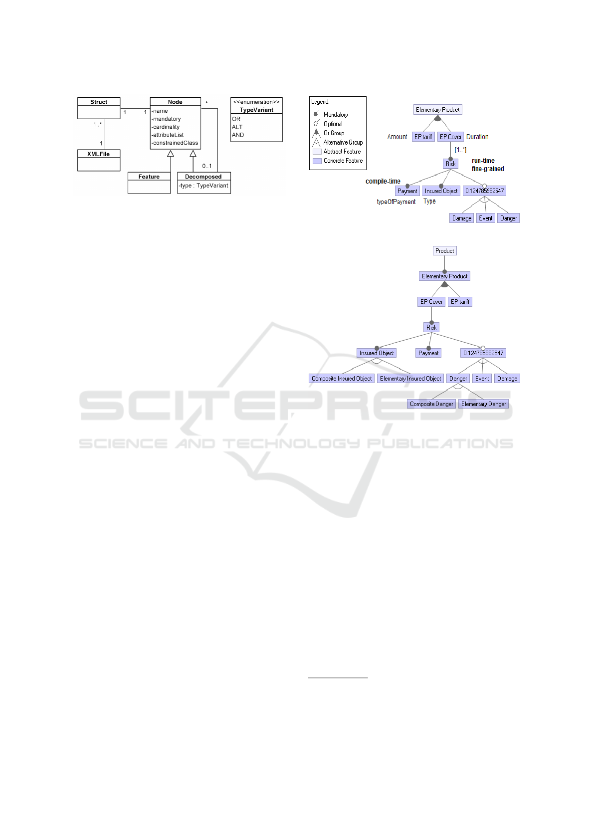
Figure 6: XML Feature language metamodel.
their dependencies. We can observe that the traver-
sal respects a logic that is subjective (for instance, the
in-depth visit of the inheritance hierarchy before the
associations and the non-deterministic choice of the
association ends to follow). We always suppose that
engineers will have to know these biases to design
correctly the DSML meta-model.
4.3 Step 3 - Marshaling to XML
The marshaling process consists of visiting the ob-
jects that represent the FM and that are stored in
the Java program and generating the XML file.
We propose a feature language based on eXtensible
Markup Language (XML) that supports cardinality,
constraints, and feature attribute notations. As illus-
trated in Fig 6, the feature language provides a FM
with features enriched with cardinality, constraints,
and a set of attributes presented by attributeList vari-
able. A feature is either simple or composed by others
with an OR, XOR, AND operator.
Since many SPL tools and configuration lan-
guages are based on XML (Jarzabek et al., 2003),
exporting the FM to XML allows engineers to con-
tinue their tasks with existing platforms in the SPL
domain. For instanbce, our DTD is readable by the
FeatureIDE plugin for Eclipse framework which al-
lows visualizing the FM, configuring valid products
and testing them. The transformation result is illus-
trated graphically in Fig. 8 with FeatureIDE which de-
prives the representation of cardinality, attributes, and
constraints information given in the XML file. Re-
gardless we recoursed this plug-in despite its flaws to
show that the generated FM is well-formed and con-
sistent and to prove that the proposed feature language
is easy to parse by PL existing plug-ins and frame-
works.
4.4 Transformation System Validation
We experimented our approach over four use cases:
two were developed by groups of master students be-
longing to the Faculty of computer science of the Uni-
Figure 7: An excerpt of Insurance System FM.
Figure 8: Resulting FM.
versity of Namur in the course INFOM434
2
: Two
proposals aim to design a software factory for E-
Learning systems. The two others were developed
for research purpose and touch on the areas of Train
Reservation system and Tourism applications. The
students metamodels are interesting since they were
not biased by the goal of producing a FM. Executing
our transformation system have led to obtain a FM
for each PL that is well-formed and conformed to our
expectations. The domain application and the corre-
sponding generated FM PL are available in a public
GitHub repository
3
. Each PL was specified in sep-
arate folder. Finally, the obtained FM is available
in both XML and graphic format in the same direc-
tory as the DSML metamodel. We also compared our
approach with a dozen other models in different do-
mains (i.e. Smart campus with IoT, and Voting sys-
tems), always in the context of the same course and
we did not detect any situations that would undermine
our approach.
2
See https://directory.unamur.be/teaching/courses/INFO
M434/2019
3
See https://github.com/Maouaheb/Academic-use-case-
validation.git.
MODELSWARD 2022 - 10th International Conference on Model-Driven Engineering and Software Development
144

5 POTENTIAL WEAKNESS
Since any study has flaws, we identify the following
weakness points: Intuitively, the engineer may not to
use our extension in accordance with the hypotheses
of the transformation process. This can be mitigated
by exposing both the annotated DSML and the result-
ing FM through synchronized views where the engi-
neer visualize the annotation feedback directly on the
FM. In addition, obtaining FM whose semantics are
not valid can not be avoided as this is an immediate
consequence of the engineer competence. In the same
way, we can not ensure that the DSML is initially
well-defined. Finally, We assumed here that DSMLs
describe a field of application with feature-like infor-
mation. But not all DSMLs are necessarily compati-
ble with our approach ADL (Architecture Description
Language), DDL (Data Definition Language), or GPL
(General Purpose Language). This limitation cannot
be considered as a weakness.
6 RELATED WORK
In the literature, contributions attempting to transform
DSML to FM are still in infancy. Hence, in this sec-
tion we sum up most notable relevant research meant
to convert any model type to a FM.
On the first hand, the method Clafer (B ˛ak et al.,
2016) is designed as a concise notation for metamod-
els, feature models, and mixtures of meta and feature
models. It has a concise syntax with rich semantics.
In fact, Clafer subsumes cardinality-based feature
modelling with attributes, references, and constraints.
However, there exists some issues to deal with the
risk for incomprehensibility as soon as the system be-
comes complex. On the second hand, Possompes et
al. (Possompès et al., 2010) proposes an instrumented
approach to integrate FM and UML metamodels with
an appropriate semantics via UML profiles. They
choose to transform feature metamodel into UML
profile to sum up FM existing semantics and by the
way facilitating their integration. This profile reuses
features related concepts by creating stereotypes that
extend UML meta-classes to add these lasts or sub-
tract them the corresponding FM semantics. At this
level, we claim that the common criticism of these
approaches is that they do not present a solution for
transforming DSML metamodel into FM. They pro-
posed new manners for either merging both of them
inside one model, which affects the system compre-
hensibility and lacks for a graphic visualization, ei-
ther including FM semantics with UML components
via profiles. However, at the best of our knowledge
none of them proposed a method to transform DSML
to FM.
7 CONCLUSION AND FUTURE
WORK
This paper presents a transformation system that con-
verts a DSML metamodel into an FM enriched with
different types of information such as feature cardi-
nality, attributes and constraints. The resulting FM
is available both in a Java abstract syntax tree and
in a serialized form with XML compatible with Fea-
tureIDE. On this basis, the engineer can then specify
the requirements for the variation points, i.e. granu-
larity, binding time, etc. This FM allows for a set of
implementation tactics that are compatible with the
above PL requirements.
In the future, we plan to have the whole produc-
tion chain supported by a metaCASE that would man-
age the DSMLs, the FM, the annotation of the differ-
ent models and the guidance of the engineer in the
design of the software factory.
REFERENCES
B ˛ak, K., Diskin, Z., and Antkiewicz, M. (2016). Clafer:
unifying class and feature modeling. Software & Sys-
tems Modeling, 15(3):811–845.
Belarbi, M. and Englebert, V. (2019). Bespoke: a method-
ology to design software factories. a preliminary ap-
proach. In 2019 13th International Conference on
Research Challenges in Information Science (RCIS),
pages 1–6. IEEE.
Burgueño, L. and Cabot, J. (2019). The future of model
transformation languages: An open community. Jour-
nal of Object Technology, 18(3).
Harrand, N., Fleurey, F., Morin, B., and Husa, K. E. (2016).
Thingml: a language and code generation framework
for heterogeneous targets. In Proceedings of the
ACM/IEEE 19th International Conference on Model
Driven Engineering Languages and Systems, pages
125–135.
Jarzabek, S., Bassett, P., Zhang, H., and Zhang, W. (2003).
XVCL: XML-based variant configuration language.
In 25th International Conference on Software Engi-
neering, 2003. Proceedings., pages 810–811. IEEE.
Kelly, S. and Tolvanen, J.-P. (2008). Domain-specific mod-
eling: enabling full code generation. John Wiley &
Sons.
Klare, H., Langhammer, M., and Kramer, M. E. (2016).
Projecting UML class diagrams from java code mod-
els. In 4th Workshop on View-Based, Aspect-Oriented
and Orthographic Software Modelling (VAO). VAO,
volume 16, pages 11–18.
Transforming Domain Specific Modeling Languages into Feature Models
145

Perrouin, G., Klein, J., Guelfi, N., and Jézéquel, J.-M.
(2008). Reconciling automation and flexibility in
product derivation. In 2008 12th International Soft-
ware Product Line Conference, pages 339–348. IEEE.
Possompès, T., Dony, C., Huchard, M., Rey, H., Tiberma-
cine, C., and Vasques, X. (2010). A UML profile for
feature diagrams: Initiating a model driven engineer-
ing approach for software product lines. In Journée
Lignes de Produits, pages 59–70.
Schobbens, P., Heymans, P., and Trigaux, J. (2006). Fea-
ture diagrams: A survey and a formal semantics. In
14th IEEE International Conference on Requirements
Engineering (RE 2006), 11-15 September 2006, Min-
neapolis/St.Paul, Minnesota, USA, pages 136–145.
IEEE Computer Society.
Tërnava, X. and Collet, P. (2017). On the diversity of cap-
turing variability at the implementation level. In Pro-
ceedings of the 21st International Systems and Soft-
ware Product Line Conference-Volume B, pages 81–
88.
White, J., Schmidt, D. C., Benavides, D., Trinidad, P.,
and Ruiz-Cortés, A. (2008). Automated diagnosis of
product-line configuration errors in feature models. In
2008 12th International Software Product Line Con-
ference, pages 225–234. IEEE.
MODELSWARD 2022 - 10th International Conference on Model-Driven Engineering and Software Development
146
