
Efficient Semantic Mapping in Dynamic Environments
Christian Hofmann
a
, Mathias Fichtner
b
, Markus Lieret
c
and J
¨
org Franke
d
Institute for Factory Automation and Production Systems, Friedrich-Alexander-Universit
¨
at Erlangen-N
¨
urnberg,
Egerlandstr. 7-9, 91058 Erlangen, Germany
Keywords:
UAV, Semantic Mapping, Object Detection, Information Fusion.
Abstract:
Unmanned Aerial Vehicles (UAVs) are required to fulfill more and more complex tasks in indoor environ-
ments like inspection, stock-taking or transportation of goods. For these tasks, they need to percept objects
and obstacles in the environment, navigate safely in it and sometimes even interact with it. A step towards
generating a comprehensive environmental overview for robots are semantic maps. Nevertheless, UAVs have
several constraints concerning size, weight and power consumption and thus computational resources. In
this paper an efficient object-oriented semantic mapping approach suitable for UAVs and similar constrained
robots in dynamic environments is proposed. The approach can be completely executed on a computer suited
as onboard computer of an UAV. A map comprising semantic information and dynamic objects is generated
and updated with update rate of more than 10 Hz.
1 INTRODUCTION
The number of applications using unmanned aerial
vehicles (UAVs) is increasing rapidly. UAVs offer
advantages for several indoor applications, for exam-
ple for stock-taking (Kalinov et al., 2020) and trans-
portation of goods (Lieret et al., 2019), as they can
reach positions at a high altitude easily and move
quickly. Especially in indoor environments, like in
(Lieret et al., 2019) and (Kalinov et al., 2020), it is
essential for an autonomous robot to have an up-to-
date environment map, which is precise and rich of
information about objects and obstacles in the envi-
ronment, i.e. a semantic map. Semantic maps enable
robots to fulfill complex tasks and improve their inter-
action with the environment, e.g., by improved path
planning (Koch et al., 2019) and navigation.
There exist several approaches for semantic map-
ping (cf. section 2). Nevertheless, these approaches
are not suited to be executed on resource constrained
UAVs (or other similar constrained robots) while pro-
viding a sufficient map update rate to also include dy-
namic obstacles in the semantic map.
In this paper, we present a semantic mapping
approach, which can run on hardware suited as an
a
https://orcid.org/0000-0003-1720-6948
b
https://orcid.org/0000-0001-9335-4884
c
https://orcid.org/0000-0001-9585-0128
d
https://orcid.org/0000-0003-0700-2028
UAV’s onboard computer while providing a map up-
date rate of more than 10 Hz for specific important
objects, like persons or moving obstacles.
The main contributions of this paper are the ar-
chitecture of the data processing pipeline for obtain-
ing an object-oriented semantic map and the method
of efficiently maintaining the object-oriented seman-
tic map.
Due to the resource constraints on UAVs, it is not
our goal to generate a semantic map comprising se-
mantic information for all objects in the environment.
Based on the discussion regarding semantic map rep-
resentations in (Cadena et al., 2016), we have the
opinion, that it is sufficient for many applications, if
only semantic information of application relevant ob-
jects is incorporated in the map, while all other ob-
jects and obstacles are simply mapped as obstacles
without further semantic information. Subsequently,
our resulting map consists of two layers, a sparse se-
mantic layer, comprising only highly relevant objects
in the environment, and a dense obstacle map layer,
comprising no semantic information.
The paper is structured as follows: First, we
present and discuss related work and motivate our
mapping approach. In the next two sections, our
data processing pipeline and the semantic mapping
method is introduced. In section 5 experiments and
the evaluation in a real world scenario are presented.
Finally, a brief summary and outlook is given.
Hofmann, C., Fichtner, M., Lieret, M. and Franke, J.
Efficient Semantic Mapping in Dynamic Environments.
DOI: 10.5220/0010770200003124
In Proceedings of the 17th International Joint Conference on Computer Vision, Imaging and Computer Graphics Theory and Applications (VISIGRAPP 2022) - Volume 4: VISAPP, pages
803-810
ISBN: 978-989-758-555-5; ISSN: 2184-4321
Copyright
c
2022 by SCITEPRESS – Science and Technology Publications, Lda. All rights reserved
803

2 RELATED WORK
There exist several approaches for building and up-
dating semantic maps. Sunderhauf et al. propose a
semantic mapping approach, that creates an object-
oriented semantic map by using a convolutional neu-
ral network (CNN) for object detection in camera im-
ages followed by a plane based 3D segmentation to
obtain the objects’ 3D position and shape (Sunderhauf
et al., 2017). The data association for updating the
map with newly detected objects is based on their eu-
clidean distance and point cloud similarity. Another
object-oriented approach is presented in (Nakajima
and Saito, 2019). It is running in real-time, but on
powerful hardware, that is not suited to be mounted on
an UAV. The algorithm uses a combination of a CNN
for object detection in images and geometric segmen-
tation of 3D data to generate 3D object detections for
the semantic map. In (Grinvald et al., 2019) a vol-
umetric, i.e. dense, semantic map is created by an
instance segmentation neural network and geometric
segmentation based on RGB-D camera data to detect
and segment objects in 3D. The data association is
mainly based on matching 3D data. This approach
needs high computational resources and runs with a
low update rate. A semantic simultaneous localiza-
tion an mapping (SLAM) approach is presented in
(Mccormac et al., 2018). It uses an instance seg-
mentation CNN for detecting objects in camera im-
ages. The semantic mapping is tightly integrated in
the SLAM process.
An approach for semantic mapping and path plan-
ning for UAVs is presented in (Koch et al., 2019).
The approach targets 3D-Reconstruction using im-
ages captured by an UAV in outdoor scenarios. For
generating a semantic map, first images of the area
are captured during an exploration flight. With these
images a semantic reconstruction of the environment
is generated using pixel-wise dense semantic segmen-
tation by a fully convolutional network and structure
from motion and multi-view stereo pipelines using an
offboard computer. Based on the semantic environ-
ment reconstruction, an improved flight path for im-
age acquisition for the 3D reconstruction is generated.
In (Maturana et al., 2017) a 2.5 D semantic mapping
approach using the UAV’s onboard computer for out-
door scenarios is presented. With a novel semantic
segmentation neural network objects are segmented
in camera images. By ray casting, the object detec-
tions are projected on a digital elevation map of the
environment to generate a 2.5 D semantic grid map.
None of these approaches is suited for indoor se-
mantic mapping with autonomous UAVs:
Since dynamic objects like persons are likely
present in indoor environments, a sufficient map up-
date rate is necessary for navigation based on the se-
mantic map. The semantic mapping approaches in
(Sunderhauf et al., 2017), (Nakajima and Saito, 2019)
(Grinvald et al., 2019) and (Mccormac et al., 2018)
are not capable of providing such an update rate on
currently available computers suited for onboard use
on UAVs. Additionally, including dynamic objects in
the map is not addressed by these approaches.
As performed for generating the semantic envi-
ronment reconstruction by (Koch et al., 2019), com-
putational demanding tasks could be outsourced to an
offboard computer. However, thus the UAV would
not be autonomous. Our approach is completely exe-
cutable on an UAV’s onboard computer. Further, the
approaches in (Koch et al., 2019) and (Maturana et al.,
2017) are designed for outdoor scenarios. For indoor
navigation, a 3D map of all obstacles is necessary,
while in our opinion only semantic information of rel-
evant objects in the environment is sufficient. Never-
theless, the objects in the semantic map should be also
mapped in 3D.
We also do not target a semantic SLAM system,
like presented in (Mccormac et al., 2018). Com-
monly, the pose and state of the UAV is estimated
by a flight control unit (FCU) on the UAV. Thus, the
UAV’s pose is already available. In indoor scenarios
the FCU’s pose estimation can be enhanced e.g., by
indoor radio based localization (Lieret et al., 2019) or
visual odometry (e.g., Intel Tracking Camera T265).
3 DATA PROCESSING PIPELINE
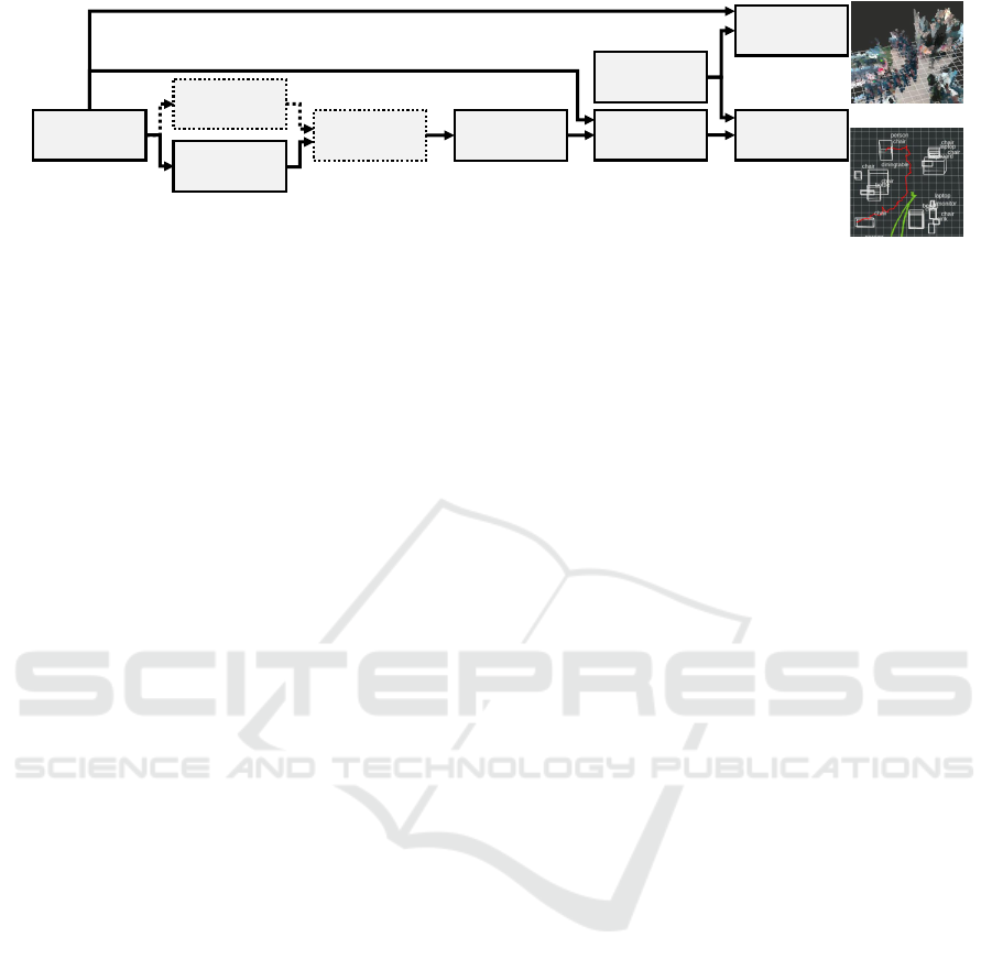
An overview of our proposed data processing pipeline
for obtaining the object-oriented semantic map is
given in Figure 1. We define consecutive modules for
data processing. Our approach relies on color images
and 3D point clouds aligned with the images as input
data. This sensory information is either directly emit-
ted or can be computed by using a RGB-D camera.
Cameras of this type are lightweight and small while
providing a sufficiently large field-of-view, making
them suited for UAVs. We assume the pose of the
UAV and thus of the camera is provided.
3.1 Object Detection
Our approach is designed to work with one or mul-
tiple object detectors using the color images as in-
put. Considering computational efficiency, the use of
a single object detector is preferable. Nevertheless,
VISAPP 2022 - 17th International Conference on Computer Vision Theory and Applications
804
RGB-D
Camera
Object
Detection
Detection
Fusion
Detection
Tracking
Detection
Segmentation
Semantic
Mapping
Camera Pose
Object
Detection
Class
Confidence
2D Bounding Box
Class
Confidence
2D Bounding Box
Class
Confidence
2D Bounding Box
Tracking ID
Class
Confidence
Tracking ID
3D Bounding Box
Image
3D
data
Pose
3D Mapping
Figure 1: Overview of our proposed data processing pipeline for object-oriented semantic mapping in dynamic environments.
it has been shown that fusing multiple object detec-
tors can improve the detection results (Solovyev et al.,
2021) (Hofmann et al., 2019). The pipeline is mod-
ular, so that, depending on the application and the
available computational resources, both options can
be implemented without any adaptions in the pipeline.
In case of using multiple detectors, they are intended
to perform object detection simultaneously.
Each detection d
i
∈ D
t
, with D
t
denoting all de-
tections provided by a detector in an image captured
at time t and i ∈ [0, I], where I is the total number of
detections in D
t
, should comprise following elements:
• Class s
i
• Confidence score c
i
for the detection, c
i
∈ [0, 1]
• 2D bounding box b
2D
i
enclosing the detection
Since it is relevant for updating the semantic map, the
detectors must also provide an output if no detections
are made by passing the timestamp t of the image pro-
cessed to semantic mapping module. Consequently, t
must be also passed through the following modules.
For the evaluation in section 5 we have imple-
mented the pipeline using these exemplary detectors:
• The CNN Tiny-YOLOv4 (following named
YOLO) (Bochkovskiy et al., 2020)
• The approach for detecting moving objects with a
moving camera presented in (Yi et al., 2013)
These two detectors were chosen for our particular ap-
plication since they cover two essential kinds of ob-
ject types: 1) objects highly relevant to the robot’s
task which are known a priori and can thus be learnt
(YOLO, in section 5 weights based on the COCO
dataset are used), and 2) dynamic obstacles, i.e. mov-
ing objects. Nevertheless, any object detector that
provides bounding boxes as detection result could be
integrated into the pipeline.
3.2 Detection Fusion
In case of using multiple detectors, following all de-
tections D
t
provided by the detectors originating in
the same image are fused. As shown for example in
(Solovyev et al., 2021) and (Hofmann et al., 2019)
the bounding boxes, classes and confidences are suf-
ficient to fuse the detections.
For the implementation of the pipeline to evalu-
ate the approach (section 5), we have adapted the al-
gorithm presented in (Solovyev et al., 2021) for our
detector selection: The incoming detections can con-
sist of detections by YOLO D
Y
t
⊆ D
t
and motion de-
tections D
MO
t
⊆ D
t
. First, for each YOLO detection
d
Y
j
∈ D
Y
t
, with j ∈ [0, J] and J being the total num-
ber of detections in D
Y
t
, the intersection-over-union
(IOU) with each motion detection d
MO
k
∈ D
MO
t
, with
k ∈ [0, K] and K being the total number of detec-
tions in D
MO
t
, using their respective bounding boxes
b
2D,Y
j
and b
2D,MO
k
is calculated. Following the detec-
tions are clustered by assigning each motion detec-
tion d
MO
k
∈ D
MO
t
to the YOLO detection d
Y
j
∈ D
Y
t
with which it has the highest overall IOU, but only if
this IOU exceeds a minimal threshold. Subsequently,
if there is more than one bounding box in a cluster,
i.e. one or more d
MO
k
are assigned to d
Y
j
, the bound-
ing boxes are fused. The bounding box b
2D,Fusion
j
and
the confidence score c
Fusion
j
of the resulting detection
d
Fusion
j
is calculated based on the original bounding
boxes, as described in (Solovyev et al., 2021). With
our exemplary detectors, the semantic information is
fused according to (Hofmann et al., 2019), resulting
for example in the class dynamic person, if a detected
person is fused with a motion detection.
The output of this step are the fused detections
D
Fusion
t
and all detections that were not fused, all to-
gether following again denoted by D
t
.
3.3 Detection Tracking
We integrated object tracking in our pipeline, because
the data association between object detections in con-
secutive images can thus already be performed com-
putationally efficient in the 2D image space. Tracking
based on bounding boxes is demonstrated for exam-
ple in (Bewley et al., 2016). In this processing step,
a tracking identifier (ID) a is added to all input detec-
Efficient Semantic Mapping in Dynamic Environments
805

tions D
t
. If a detection d
i
∈ D
t
is tracked, i.e. it is as-
sociated with a prior detection, its tracking ID a
i
is set
to a specific value, which is the same for all detections
associated with each other by the same tracker (Bew-
ley et al., 2016). If a detection d
i
can’t be tracked, the
tracking ID should be set to a defined value. All de-
tections D
t
are passed to the following segmentation
module. The algorithm described in (Bewley et al.,
2016) is used for the evaluation in Section 5.
3.4 Detection Segmentation
Since the goal is a 3D object-oriented semantic map,
the detected objects are transformed from image
space to 3D space and segmented.
For each incoming detection d
i
∈ D
t
, the 3D
points P
i
⊆ P
t
corresponding to the pixels inside the
detection’s 2D bounding box b
2D
i
are extracted from
the point cloud P
t
. The point cloud P
t
corresponds
to the color image in which the detections D
t
were
made. Since often the bounding box b
2D
i
encloses not
solely the detected object, but also pixels and subse-
quently 3D points belonging to the background and
other objects, each detection’s point cloud is filtered.
First, the point cloud is downsampled using a voxel
grid filter. Following, the point cloud P
i
is clustered
using euclidean cluster extraction. For determining,
which cluster L
r
⊆ P
i
, with r ∈ [1, R] and R being the
total number of clusters found in P
i
, represents the
object detected in the image, we rely on two charac-
teristics: 1) Normally, the bounding box b
2D
i
should
enclose the detected object tightly in the image, so
that most pixels in b
2D
i
belong to the detected object
and thus most points in P
i
. 2) Further, the detected
object should most probably be present in the center
of the bounding box b
2D
i
(Hofmann et al., 2019). The
cluster L
r
⊆ P
i
is chosen to represent the detected ob-
ject, which has the maximal score
v
L
r
= w ·
q
L
r
q
P
i
+ (1 − w) ·
h
L
r
h
P
i
,max
, (1)
where v
L
r
is the resulting score of the cluster L
r
,
w ∈ [0, 1] is a weighting factor for the influence of
the two characteristics, q
L
r
is the number of points in
the cluster L
r
and q
P
i
is the number of points in P
i
.
h
L
r
is the euclidean distance of the cluster’s center to
the 3D center of the 2D bounding box b
2D
i
. This 3D
center is prior calculated by extracting the points of P
t
corresponding to the pixel in a certain area around the
2D center of b
2D
i
and calculating their mean 3D po-
sition. h
P
i
,max
is the maximal possible euclidean dis-
tance between two points in P
i
, i.e. the euclidean dis-
tance of an imaginary point x
min
= [x
min
, y
min
, z
min
]
T
,
where [x
min
, y
min
, z
min
]
T
are the minimal coordinates
for each axis present in the point cloud P
i
, to an
imaginary point x
max
with the maximal coordinates
[x
max
, y
max
, z
max
]
T
for each axis in P
i
.
The detected object’s 3D position x
camera
i
is de-
fined as the center of the cluster L
r
with the highest
score v
L
r
. The 3D bounding box b
3D,camera
i
is calcu-
lated to enclose all points in this cluster. The position
x
camera
i
and 3D bounding box b
3D,camera
i
are at this step
expressed in relation to the camera frame, not the map
frame, which differ as the camera is moving.
In case the calculation of x
camera
i
and b
3D,camera
i
is
not possible, e.g., if there are no valid points in the
point cloud, the detection d
i
is not passed further. If
this is the case for all d
i
∈ D
t
, the timestamp t must
be passed for updating the map, providing the infor-
mation that no valid detections were made.
We use 3D bounding boxes to represent objects
in the map, as they are computational more efficient
than point clouds. However, also the segmented point
clouds could be used for the semantic mapping.
We developed this detector-independent segmen-
tation approach, since by this the detectors can be eas-
ily changed for different applications, while the seg-
mentation can be always applied. The implementa-
tion for the evaluation in section 5 is based on the
point cloud library (PCL) (Rusu and Cousins, 2011).
3.5 Mapping
Based on the results of the segmentation step, the
sparse object-oriented semantic map is created. To
also map objects and obstacles that cannot be de-
tected, a further mapping approach should be used
to create a complete (non-semantic) 3D map of the
environment (cf. Figure 1). For example, RTAB-
Map (Labb
´
e and Michaud, 2019), which we also use
in the experiments in section 5, is well suited, as it
also works with RGB-D data. Simultaneous to the
map generated by RTAB-Map, our semantic mapping
approach outputs the object map comprising relevant
and moving objects (depending on the detector selec-
tion) at a relatively high update rate.
4 SEMANTIC MAPPING
Our object-oriented semantic map at time t
M
t
= {o
1,t
, ..., o
N,t
} (2)
consists of N objects o
n,t
with n ∈ [0, N]. The map M
t
is time dependent, as objects can be added or deleted,
depending on the detections D
t
made in the image
captured at time t. Following the time (i.e. the times-
VISAPP 2022 - 17th International Conference on Computer Vision Theory and Applications
806

tamp) corresponding to the detections made right be-
fore the current detections D
t
is denoted as t − 1. This
means M
t−1
denotes the map before updating it with
the detections D
t
, resulting in M
t
.
Each object o
n,t
∈ M
t
comprises the following in-
formation:
• Object class s
n,t
• Indicator g
n,t
, whether the object is currently dy-
namic (g
n,t
= true) or static (g
n,t
= false),
• Tracking ID a
n,t
, which is the tracking ID of the
last detection associated with the object
• The object’s position x
map
n,t
in the map
• 3D Bounding Box b
3D,map
n,t
to store the object’s
size
• Counter for the number of updates of o
n,t
• Persistence filter (Rosen et al., 2016), which esti-
mates whether an object is still present in the en-
vironment or disappeared
• Persistence probability u
n,t
, which indicates the
probability, that the object is still present, esti-
mated by the object’s persistence filter
Besides the current detections D
t
, the camera’s pose
p
map
t
at time t in the map is passed to the mapping
module (cf. Figure 1). The map M
t−1
is updated to
M
t
with every incoming object measurement, even if
no detections (so only the timestamp t of the input im-
age) is passed. The update step to generate M
t
from
M
t−1
is structured as follows:
1) Detection Transform Step: For each incoming de-
tection d
i
∈ D
t
, its position x
camera
i
and 3D bounding
box b
3D,camera
i
are transformed from the camera frame
to the map frame by using the camera’s pose p
map
t
re-
sulting in x
map
i
and b
3D,map
i
.
2) Expectation Step: With p
map
t
, it is calculated,
which objects in the prior map, o
n,t−1
∈ M
t−1
, should
be detected in current image and so be in D
t
by pro-
jecting each object’s 3D position x
map
n,t−1
that is in a
certain radius in front of the camera, into the camera’s
image plane. For this, the camera’s intrinsic parame-
ters are necessary and must be provided once when
starting the mapping. All objects o
n,t−1
∈ M
t−1
that
should be visible in the current image and so be in D
t
are marked as ”expected objects”.
3) Data Association Step: First, it is checked for each
incoming detection d
i
∈ D
t
, if its tracking ID a
i
is al-
ready stored in the tracking ID a
n,t−1
of any object
o
n,t−1
∈ M
t−1
. If so, it is checked if the euclidean dis-
tance between the detection’s position x
map
i
and ob-
ject’s position x
map
n,t−1
is smaller then a threshold dis-
tance. If this condition is fulfilled, the detection d
i
is associated with the object o
n,t−1
. Otherwise, each
detection’s position x
map
i
and class s
i
with all not yet
associated objects o
n,t−1
∈ M
t−1
are compared. It is
checked whether the euclidean distance between the
positions x
map
i
and x
map
n,t−1
is smaller than a threshold
distance and the classes s
i
and s
n,t−1
are equal. In case
these conditions are fulfilled, the IOU between the de-
tection’s 3D bounding box b
map
3D,i
and the object’s 3D
bounding box b
map
3D,n,t−1
is calculated. For this, the de-
tection’s 3D bounding box b
map
3D,i
is shifted to the ob-
ject’s position x
map
n,t−1
. If the 3D IOU value exceeds
a threshold, d
i
is noted as association candidate for
o
n,t−1
. The detection d
i
is associated with the object
o
n,t−1
providing the highest IOU. The underlying as-
sumption is, that a real world object’s size and so the
resulting 3D bounding box should be relatively con-
stant. This process is inspired by the data association
described in (Sunderhauf et al., 2017).
4) Map Update Step: If an object o
n,t−1
∈ M
t−1
is
associated with a detection d
i
∈ D
t
, following update
steps to obtain o
n,t
are performed:
The class s
n,t
of o
n,t
is set to the detection’s class s
i
.
However, s
n,t−1
and s
i
and consequently s
n,t
should be
identically based on the data association.
If d
i
is a dynamic object, g
n,t
is set true, otherwise it
is set to false.
If the detection d
i
has a valid tracking ID a
i
, the ob-
ject’s tracking ID a
n,t
is updated with this one.
If the object is dynamic, i.e. g
n,t
= true, the object’s
new position x
map
n,t
is set to the detection’s position
x
map
i
, assuming the object is moving. Else, we assume
the object is static, x
map
n,t
is calculated as the weighted
mean of x
map
i
and x
map
n,t−1
, where x
map
i
has the weight
1 and x
map
n,t−1
has a weight equal to the number of the
object’s prior updates.
The weighted mean is also used in the same man-
ner to update the size of the object’s 3D bounding
box b
3D,map
n,t
based on b
3D,map
i
(weight 1) and b
3D,map
n,t−1
(weight equal to the number prior updates). The cen-
ter of b
3D,map
n,t
is x
map
n,t
.
The number of updates for o
n,t
is increased by 1.
If an object o
n,t−1
is marked as ”expected object”, but
is not associated with any current detection d
i
∈ D
t
,
the object’s persistence filter is accordingly updated
with ”false”, i.e. the object was not detected, leading
to a decreased persistence probability u
n,t
of o
n,t
.
If an object o
n,t−1
is marked as ”expected object”, and
is associated with a current detection d
i
∈ D
t
the ob-
ject’s persistence filter is accordingly updated with
”true”, i.e. the object was detected, leading to a in-
creased or static persistence probability u
n,t
.
Not expected static objects o
n,t−1
∈ M
t−1
, that are not
associated with a detection d
i
∈ D
t
, are not updated.
For not expected dynamic objects o
n,t−1
∈ M
t−1
,
Efficient Semantic Mapping in Dynamic Environments
807

which are not associated with a detection, the per-
sistence probability u
n,t
for the current time t is pre-
dicted using its persistence filter, normally leading to
a decreased persistence probability u
n,t
of o
n,t
. This is
based on the assumption that the object moves, i.e. it
should also disappear in the map.
If a detection d
i
∈ D
t
is not associated with any object
in M
t−1
, it is added as new object to the map M
t
.
Finally, after this update process it is checked,
whether the persistence probability u
n,t
of any ob-
ject o
n,t
∈ M
t
is lower than a threshold. If so, o
n,t
is deleted from map, assuming it disappeared. All re-
maining objects o
n,t
are then representing the updated
object-oriented semantic map M
t
.
5 EXPERIMENTS AND
EVALUATION
Following, the evaluation of our approach in a real
world scenario with focus on the semantic map is pre-
sented. We use an Intel Realsense D435 RGB-D cam-
era with the resolution set to 640 x 480 pixel (RGB
and aligned point cloud) and the frame rate set to 15
Hz. To continuously obtain the 3D pose of the RGB-
D camera, we use an Intel Realsense T265 Tracking
camera, fixed with the RGB-D camera on a plate (to-
tal size: 108 x 100 x 30 mm). As computer for data
processing we use an NVIDIA Jetson Xavier NX (15
watt and 6 cores mode), which is well suited to be
used on UAVs (size with case for mounting: 130 x 92
x 41 mm). The setup (computer with case, two cam-
eras with plate) has a total weight of 541 grams. Due
to safety reasons, we carried the Jetson and the cam-
eras by hand for data acquisition. We saved the raw
camera data and used it to evaluate our approach with
different configurations running on the Jetson.
Only detections by YOLO, which is executed us-
ing the Jetson’s GPU, that have a detection confidence
exceeding 0.5 are passed to the pipeline. Further, de-
tections by the motion detector are filtered by only
passing detections enclosing more than 1000 pixels
to reduce false detections caused by camera motion.
For the detection segmentation, we choose the down-
sampling voxel size to 0.05 m and the weight factor to
w = 0.75. Further, only segmented detections that are
within a radius of 5 m around the camera are used, as
the point cloud provided by the D435 camera is very
noisy in larger distances. For the persistence filter we
set, as suggested by (Rosen et al., 2016), exponen-
tial priors for the survival function with the fixed rate
parameters of 0.001 in case of static objects and 1.5
otherwise. By this, dynamic objects are deleted rel-
atively fast if they are not detected any more, while
static objects remain in the map. We set the proba-
bility for false detections to 0.3, for missed detections
to 0.6, empirically based on the used detectors and
the scenario. For data association, we set the distance
threshold to 1.0 m and the minimal IOU to 0.01.
Using the two detectors, a semantic map update
rate of 10 to 15 Hz on the Jetson is obtained, depend-
ing on the observed scene and the number of objects
in the semantic map. This means, not every cam-
era measurement is incorporated in the semantic map.
All prior modules of our pipeline including the seg-
mentation module output their results at a rate of 15
Hz, thus, they evaluate almost all input data. The Jet-
son’s CPU is utilized between 60 and 90 percent when
executing the whole pipeline comprising the two de-
tectors as well as RTAB-Map in SLAM-Mode. This
value is reduced to 40 to 70 percent while the seman-
tic map update rate is increased to 14 to 15 Hz, when
using YOLO as only detector, but no motion detec-
tion and consequently no detection fusion. Using this
configuration, it is possible to execute further compu-
tationally intensive tasks onboard. Further software
optimizations should also reduce the CPU utilization.
Following, the key findings obtained by our exper-
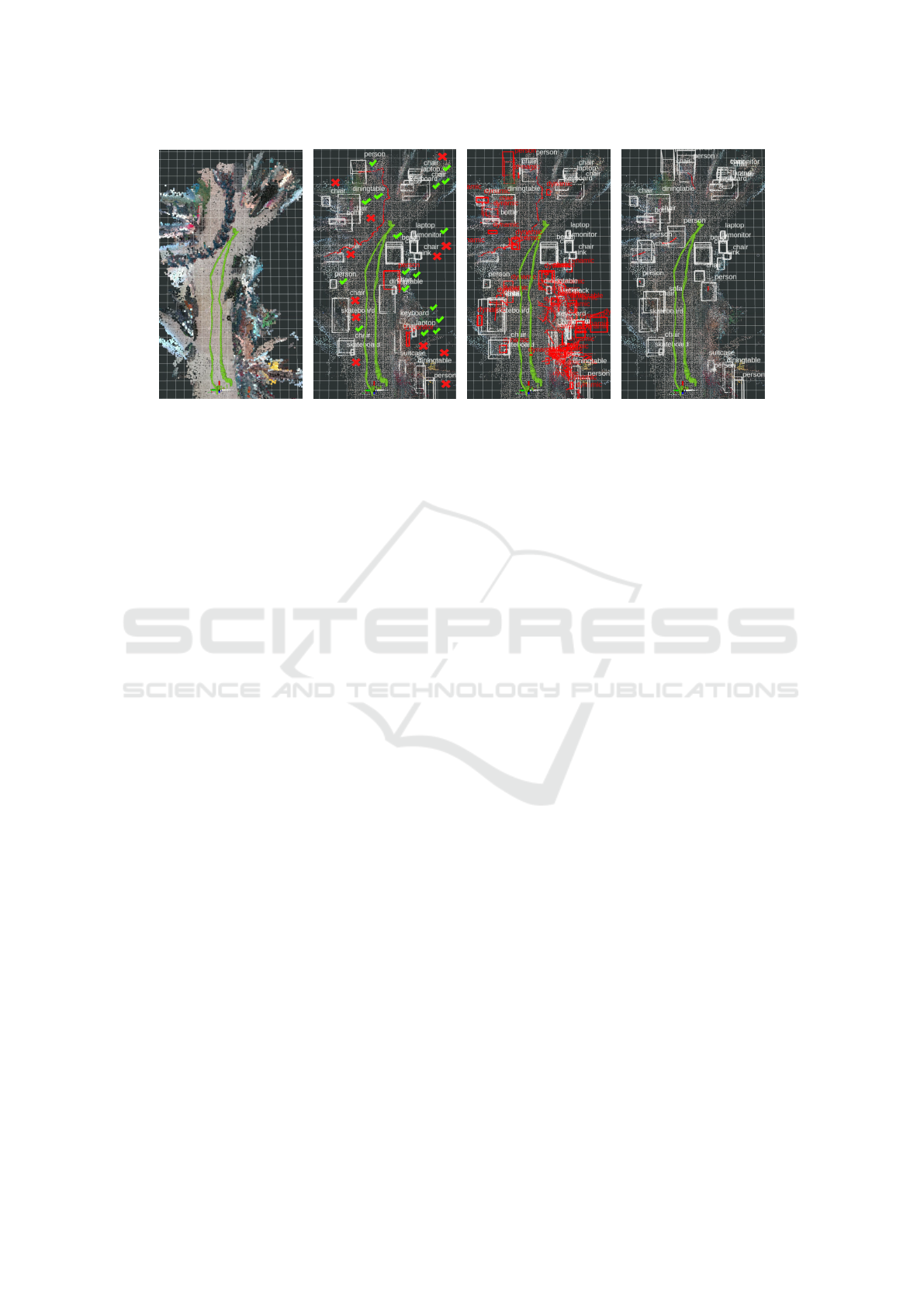
iments are described. Figure 2a shows the point cloud
map obtained by RTAB-Map without any semantic in-
formation. The point cloud map of RTAB-Map is not
cleared, thus the person moving (from the middle left
in the picture to the top) appears several times, dis-
playing the trajectory well.
In Figure 2b the semantic map generated using the
two object detectors is pictured. The detected seman-
tic objects fit well to the point cloud map. Neverthe-
less, there are several false objects in the map as well
as missing objects. This is mainly based on wrong and
missed detections by YOLO. Thus, a more accurate
detector should improve the result. However, often
the trade-off between detection accuracy and compu-
tational efficiency has to be considered. Another in-
fluence to the object detection are blurry images out-
put by the D435 camera due to camera motion. This
makes it difficult to detect objects and causes wrong
motion detections (e.g., a tv-monitor with a red box
in the bottom right). A camera with global shutter
should solve this problem.
Further, it is not easy to determine whether some
detections are false or correct. An overview is given
in Figure 2b by the check marks for correct objects in
the map and x’s for wrong objects. In several cases
YOLO detected objects with similar classes in differ-
ent images for the same real world object. Examples
are a chair also detected as bench in the middle right
and several monitors also detected as laptop. To over-
come this, a data association algorithm that also com-
VISAPP 2022 - 17th International Conference on Computer Vision Theory and Applications
808
(a) (b) (c) (d)
Figure 2: Resulting maps of our real world scenario comprising the point cloud map generated by RTAB-Map and our object-
oriented semantic map with three different configurations. Picture (a) shows the point cloud map of RTAB-Map without our
semantic map and point size set to 0.1 m. Pictures (b), (c), and (d) present maps obtained using the configuration described in
section 5 with two detectors (b), with deactivated persistence filter for all objects (c) and with YOLO as only object detector
(d). The point size of the point cloud map generated by RTAB-Map in those maps is set to 0.03 m. Static objects are displayed
by white bounding boxes, dynamic ones with red. The trajectory of all persons is pictured as red line. Green arrows show the
camera’s trajectory. The green check marks in (b) show objects in the map that were correctly mapped, the red x’s show false
mapped objects. The grid has a cell size of 0.5 m.
prises the objects’ semantics could be used. Summed
up, there are 17 correct objects and 12 false objects in
the map. Nevertheless, all persons as most safety rel-
evant objects were detected correctly. Several objects
present in the real scenario are missing in the map,
because they were not detected by YOLO. Again, a
more accurate object detector explicitly trained for the
environment should improve the result.
The detected objects’ sizes fit mostly well to the
point cloud and the real world objects. Though, ob-
jects that are surrounded by many other objects have
often a too big 3D bounding box based on the point
cloud segmentation. As displayed by the camera tra-
jectory in Figure 2, many objects were mapped while
the camera only passed them. If an object is well vis-
ible in the image and the point cloud, like the per-
son at the top of the map, it is well detected and seg-
mented. Comparing pictures 2a and 2b, it is also ob-
vious that the trajectory of the moving person is cor-
rectly mapped.
Picture 2c shows a map with the each object’s per-
sistence filter deactivated, thus no objects are deleted
from the map. Accordingly, there are many wrong
motion detections in the map, originating from cam-
era movement. Comparing this with Figure 2b, all
wrong dynamic objects are filtered from the map us-
ing persistence filters for each object. Summarized,
the persistence filter works as intended and is a valu-
able object attribute to maintain the semantic map.
Figure 2d shows the map obtained when using
YOLO as only object detector. Comparing the seman-
tic map to the one in Figure 2b, the result is similar.
However, the moving person was not always detected
by YOLO and thus associated, resulting in several
mapped static persons. The motion detector detected
the moving person in some images (cf. Figure 2b), in
which YOLO could not detect the person. Thus, the
simultaneous motion detection is advantageous, but
probably not necessary for all applications. Whether
an object is probably dynamic or static, could for ex-
ample also be inferred from the object class.
Further differences between the maps in the Fig-
ures 2b and 2d are several missing objects at the bot-
tom right in Figure 2d. These differences occur, be-
cause with YOLO as only detector, more measure-
ments are incorporated in the semantic map (higher
map update rate). Thus, the missing objects are
deleted due to a low persistence probability caused by
missed detections that were now incorporated in the
map.
6 CONCLUSIONS AND FUTURE
WORK
We presented an approach for object-oriented seman-
tic mapping in dynamic environments, which is suited
for UAVs and similar robots constrained concerning
size, weight and power consumption and thus compu-
tational resources. When using only one object detec-
tor (in our experiments Tiny YOLO), the approach is
Efficient Semantic Mapping in Dynamic Environments
809

sufficently computationally efficient to allow the ex-
ecution of further software on the onboard computer.
Software optimizations should allow the use of multi-
ple detectors, leading to an improved mapping result.
Our approach achieves satisfying results in the
real world evaluation. Nevertheless, the data associa-
tion for semantic mapping could be improved by us-
ing semantic information, e.g., presented in (Doherty
et al., 2020) . In addition, more object attributes, like
uncertainties (Hiller et al., 2018), could be integrated.
Further, we plan to investigate our approach using ob-
ject detectors with higher accuracy.
ACKNOWLEDGEMENTS
This work was developed within the project
”AIRKom” funded by the Forschungsgemeinschaft
Intralogistik / Foerdertechnik und Logistiksysteme
(IFL) e.V.
REFERENCES
Bewley, A., Ge, Z., Ott, L., Ramos, F., and Upcroft, B.
(25.09.2016 - 28.09.2016). Simple online and real-
time tracking. In 2016 IEEE International Conference
on Image Processing (ICIP), pages 3464–3468. IEEE.
Bochkovskiy, A., Wang, C.-Y., and Liao, H.-Y. M.
(23.04.2020). Yolov4: Optimal speed and accuracy
of object detection.
Cadena, C., Carlone, L., Carrillo, H., Latif, Y., Scaramuzza,
D., Neira, J., Reid, I., and Leonard, J. J. (2016). Past,
present, and future of simultaneous localization and
mapping: Toward the robust-perception age. IEEE
Transactions on Robotics, 32(6):1309–1332.
Doherty, K. J., Baxter, D. P., Schneeweiss, E., and Leonard,
J. J. (31.05.2020 - 31.08.2020). Probabilistic data
association via mixture models for robust semantic
slam. In 2020 IEEE International Conference on
Robotics and Automation (ICRA), pages 1098–1104.
IEEE.
Grinvald, M., Furrer, F., Novkovic, T., Chung, J. J., Ca-
dena, C., Siegwart, R., and Nieto, J. (2019). Volu-
metric instance-aware semantic mapping and 3d ob-
ject discovery. IEEE Robotics and Automation Let-
ters, 4(3):3037–3044.
Hiller, M., Particke, F., Hofmann, C., Bey, H., and Thi-
elecke, J. (19.07.2018 - 23.07.2018). World modeling
for mobile platforms using a contextual object-based
representation of the environment. In 2018 IEEE 8th
Annual International Conference on CYBER Technol-
ogy in Automation, Control, and Intelligent Systems
(CYBER), pages 187–191. IEEE.
Hofmann, C., Particke, F., Hiller, M., and Thielecke, J.
(25.02.2019 - 27.02.2019). Object detection, classi-
fication and localization by infrastructural stereo cam-
eras. In Proceedings of the 14th International Joint
Conference on Computer Vision, Imaging and Com-
puter Graphics Theory and Applications, pages 808–
815. SCITEPRESS - Science and Technology Publi-
cations.
Kalinov, I., Petrovsky, A., Ilin, V., Pristanskiy, E.,
Kurenkov, M., Ramzhaev, V., Idrisov, I., and Tset-
serukou, D. (2020). Warevision: Cnn barcode
detection-based uav trajectory optimization for au-
tonomous warehouse stocktaking. IEEE Robotics and
Automation Letters, 5(4):6647–6653.
Koch, T., K
¨
orner, M., and Fraundorfer, F. (2019). Auto-
matic and semantically-aware 3d uav flight planning
for image-based 3d reconstruction. Remote Sensing,
11(13):1550.
Labb
´
e, M. and Michaud, F. (2019). Rtab-map as an open-
source lidar and visual simultaneous localization and
mapping library for large-scale and long-term online
operation. Journal of Field Robotics, 36(2):416–446.
Lieret, M., Kogan, V., Doll, S., and Franke, J. (22.08.2019
- 26.08.2019). Automated in-house transportation of
small load carriers with autonomous unmanned aerial
vehicles. In 2019 IEEE 15th International Confer-
ence on Automation Science and Engineering (CASE),
pages 1010–1015. IEEE.
Maturana, D., Arora, S., and Scherer, S. (24.09.2017 -
28.09.2017). Looking forward: A semantic mapping
system for scouting with micro-aerial vehicles. In
2017 IEEE/RSJ International Conference on Intelli-
gent Robots and Systems (IROS), pages 6691–6698.
IEEE.
Mccormac, J., Clark, R., Bloesch, M., Davison, A., and
Leutenegger, S. (05.09.2018 - 08.09.2018). Fusion++:
Volumetric object-level slam. In 2018 International
Conference on 3D Vision (3DV), pages 32–41. IEEE.
Nakajima, Y. and Saito, H. (2019). Efficient object-oriented
semantic mapping with object detector. IEEE Access,
7:3206–3213.
Rosen, D. M., Mason, J., and Leonard, J. J. (16.05.2016
- 21.05.2016). Towards lifelong feature-based map-
ping in semi-static environments. In 2016 IEEE In-
ternational Conference on Robotics and Automation
(ICRA), pages 1063–1070. IEEE.
Rusu, R. B. and Cousins, S. (09.05.2011 - 13.05.2011). 3d
is here: Point cloud library (pcl). In 2011 IEEE In-
ternational Conference on Robotics and Automation,
pages 1–4. IEEE.
Solovyev, R., Wang, W., and Gabruseva, T. (2021).
Weighted boxes fusion: Ensembling boxes from dif-
ferent object detection models. Image and Vision
Computing, 107:104117.
Sunderhauf, N., Pham, T. T., Latif, Y., Milford, M.,
and Reid, I. (24.09.2017 - 28.09.2017). Meaning-
ful maps with object-oriented semantic mapping. In
2017 IEEE/RSJ International Conference on Intelli-
gent Robots and Systems (IROS), pages 5079–5085.
IEEE.
Yi, K. M., Yun, K., Kim, S. W., Chang, H. J., and Choi, J. Y.
(23.06.2013 - 28.06.2013). Detection of moving ob-
jects with non-stationary cameras in 5.8ms: Bringing
motion detection to your mobile device. In 2013 IEEE
Conference on Computer Vision and Pattern Recogni-
tion Workshops, pages 27–34. IEEE.
VISAPP 2022 - 17th International Conference on Computer Vision Theory and Applications
810
