
A Real-time 3D Surround View Pipeline for Embedded Devices
Onur Eker
a
, Burak Ercan
b
, Berkant Bayraktar
c
and Murat Bal
d
Havelsan Inc., Ankara, Turkey
Keywords:
3D Surround View System, Parking Assistance System, Embedded Real-time Panorama Generation, Mesh
Video Texture.
Abstract:
In recent years, 3D surround view systems started to gain more attention as advanced driver assistance systems
(ADAS) become more capable and intelligent. A 3D surround view system provides a 360-degree view of the
environment surrounding the vehicle to enable the driver or operator to virtually observe its surroundings in
a convenient way. In this paper we propose an end-to-end algorithm pipeline for 3D surround view systems,
and show that it works in real-time on embedded devices. The proposed pipeline uses four cameras mounted
around a vehicle for image acquisition. First, images are rectified and mapped to a spherical surface to generate
2D panorama view. In mapping step, a low-cost color correction is applied to provide a uniform scene in
panorama. Lastly, generated panorama image is projected on a bowl-shaped mesh model to provide 360-
degree view of the surrounding environment. The experimental results show that the proposed method works
in real-time on desktop computers as well as on embedded devices (such as the NVIDIA Xavier); and generates
less distorted, visually appealing 360-degree surround view of the vehicle.
1 INTRODUCTION
In recent years, autonomous driving is becoming a
very popular topic in academia and industry with the
advents in the fields of deep learning and computer
vision. Advanced driver assistance systems (ADAS)
are various electronic systems in vehicles that are
composed of intelligent algorithms (such as adaptive
cruise control, collision avoidance, obstacle avoid-
ance, lane departure and lane centering) to assist the
drivers.
3D view surround systems can also be mentioned
as one of these systems and being more and more
widely used in high-end cars in the world. A 3D sur-
round view system is a vehicle camera system that
provides a composite view of the vehicle’s surround-
ing. It is a component of ADAS that improves the
safety and comfort of the driver or operator. These
systems enhance the surveillance of the surroundings
by improving visibility and field of view.
For this, several different surround view methods
have been proposed in the literature. The studies in
the field of 3D surround view systems normally con-
a
https://orcid.org/0000-0003-4040-6438
b
https://orcid.org/0000-0002-9231-7982
c
https://orcid.org/0000-0002-0772-4859
d
https://orcid.org/0000-0002-2030-7793
sist of four to six fish-eye cameras mounted around
the vehicle to eliminate any visual blind spots. They
usually follow a common pipeline: image captur-
ing, image undistorting, panorama stitching and tex-
ture mapping. Some of these methods generate a
top/bird’s-eye view from vehicle cameras that allows
the driver to watch 360-degree surroundings and it is
generally used for parking guidance.
Liu et al. (2008), develop a system consisting of
six fish-eye cameras to provide a bird-eye view of ve-
hicle’s surrounding. In their method, stitching of the
overlapping regions is achieved by propagating the
deformation field of alignment. Ehlgen and Pajdla
(2007), develop a camera system consisting of four
omnidirectional cameras for trucks. They split the
overlapping areas between adjacent images to form
a bird’s eye view image, which results in discontinu-
ity on the overlapping areas. Yu and Ma (2014), pro-
pose a flexible stitching method to smooth the seam of
the overlapping regions. They also propose a bright-
ness balance algorithm to compensate exposure dif-
ferences.
The aforementioned methods generate bird’s-eye
view system which can only provide a single per-
spective from above the vehicle. On the other hand,
3D surround view systems provide better surveillance
and awareness of the vehicle’s surrounding. Gao
Eker, O., Ercan, B., Bayraktar, B. and Bal, M.
A Real-time 3D Surround View Pipeline for Embedded Devices.
DOI: 10.5220/0010766500003124
In Proceedings of the 17th International Joint Conference on Computer Vision, Imaging and Computer Graphics Theory and Applications (VISIGRAPP 2022) - Volume 4: VISAPP, pages
257-263
ISBN: 978-989-758-555-5; ISSN: 2184-4321
Copyright
c
2022 by SCITEPRESS – Science and Technology Publications, Lda. All rights reserved
257
et al. (2017), propose a specially designed checker-
board for camera calibration and use a 3D ship model
to map the stitched image texture. Zhang et al.
(2019), propose a new hamburger-shaped 3D model
for panorama texture mapping. In their method, they
also introduce multi-band blending and graph cut al-
gorithm at the panorama stitching phase. Auysakul
et al. (2017), propose a composite projection model
which is a combination of a planar projection model
and hemi-spherical projection model to generate 3D
surround view with low distortion. Similarly, Tseng
et al. (2015) develop a surround view method that tex-
tures images to a bowl-shaped model. They also pro-
vide a method to eliminate the vignetting effect. Cha-
van and Shete (2017), proposes a method that runs
on DSP C66x processor by mapping captured images
onto 3D bowl model using inverse prospective map-
ping.
Instead of utilizing a fixed 3D mesh model,
some methods exploit data from different sensors
such as LiDAR (Baek et al., 2019) or 3D laser
rangefinder (Garc
´
ıa, 2015) to dynamically change the
3D model based on the structure of the surroundings.
However, these methods require heavy computational
power and costly additional sensors to work.
Our Contributions: In this study, we propose a
3D surround view pipeline which is highly effec-
tive in terms of frames per second (FPS) and res-
olution, while working on embedded systems with
low power consumption like NVIDIA Xavier NX. Al-
though there are methods using bowl-shaped mod-
els in 3D surround view systems, we propose three
different type of mesh models and provide the UV
mappings of those models. Also, we implement the
two-stage panorama generation step of our pipeline
to work on GPUs, in order to meet real-time opera-
tion requirement. In addition, we employ a novel and
highly efficient color correction method to align im-
ages photometrically to produce seamless panorama
images in real-time. We also provide extensive eval-
uations both on PC and NVIDIA embedded devices
to show efficiency and usability of the proposed
pipeline.
2 METHOD
In this study, we propose a low-cost 3D surround view
application that runs on GPU and operates in real-
time on embedded devices. To this end, we use Air-
Sim (Shah et al., 2018), a visually realistic simula-
tor launched by Microsoft Research, to develop and
test our method. The main steps applied for this pur-
pose are analyzed under the following sections: image
acquisition, panorama generation, color correction,
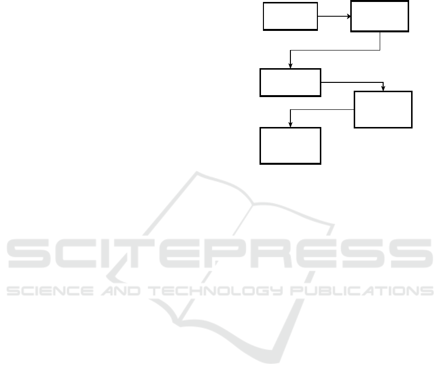
mesh generation and texture mapping. An overview
of the proposed end-to-end 3D surround view pipeline
is given in Figure 1.
Image Acquistion Panorama Generation
Color Correction
Mesh Generation and
Texture Mapping
Bird's Eye and Surround
View Output
Figure 1: Overview of the proposed end-to-end 3D sur-
round view pipeline.
2.1 Image Acquisition
In this study, we use AirSim simulator that offers
physically and visually realistic simulations which is
built on top of Unreal Engine. The modular design
of the simulator enables us to put multiple cameras
on a vehicle with desired field of view. Our vehicle
simulation system consists of four cameras mounted
around the vehicle. All of the cameras are distributed
at the top of the vehicle symmetrically, as one look-
ing forward, one backward, and two for left and right
sides, with a 90-degree rotation between each camera.
The cameras have 100-degrees field of view and this
provides sufficient overlap between each view. Next,
a standard checkerboard camera calibration process is
applied to get intrinsic camera parameters and rectify
images to fuse all undistorted images into a panorama.
2.2 Panorama Generation
Texture mapping generally involves both placing a
2D texture on a 3D surface and fitting the surface to
a particular object (Bier and Sloan, 1986). In this
study, mapping of the camera images to a 3D bowl-
shaped model is achieved by using a two-stage map-
ping method. This two-stage approach reduces the
image distortion and enriches the context informa-
tion (Gao et al., 2017). In the intermediate mapping
step (2D panorama generation step) we used spherical
mapping to project input images onto a sphere:
VISAPP 2022 - 17th International Conference on Computer Vision Theory and Applications
258
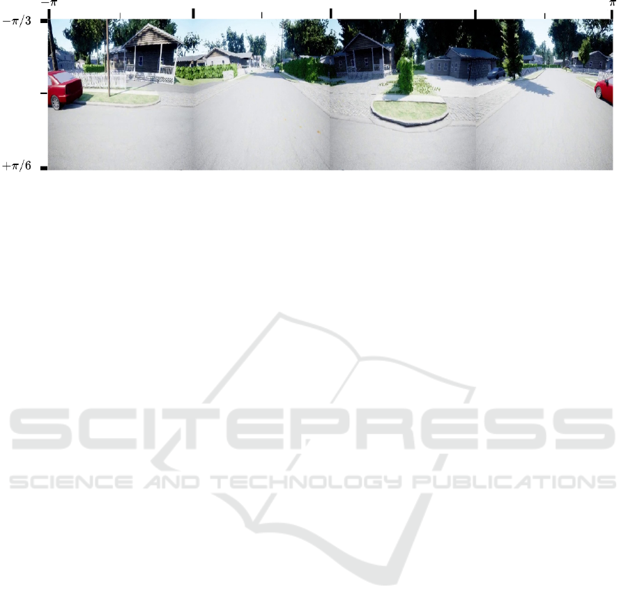
Figure 2: Generated panorama image with spherical mapping on AirSim.
x = R × cosα × sinβ
y = R × sinα × cosβ
z = R × cosβ,
(1)
where R is the radius of the sphere, α is the angle be-
tween the optical center and the X axis, and β is the
angle between the optical center and the Y axis, where
0 ≤ α, β ≤ 2π. The radius R is set equal to the optical
focal length, which is determined at the camera cali-
bration step. In the simulation configuration, we put
each camera symmetrically and with a 90-degree be-
tween each view. We mapped each camera image to
the sphere based on the angle of it’s optical axis to the
center of the vehicle. Next, at the initialization step,
we generated a look-up table. In the look-up table,
we kept the mapping location information for each
pixel. This approach speeds-up the online panorama
mapping process and we implement this operation on
GPU to reduce the execution time even further. Figure
2 shows the resulting panorama image of the interme-
diate spherical mapping.
2.3 Color Correction
The panorama generation step maps each camera im-
age to a common image surface by geometrically
aligning them, in order to produce a composite sur-
round view. In an ideal composite image, the bound-
aries between images from different cameras should
be seamless. The geometric alignment ensures the
continuity in image boundaries, such that the sur-
rounding 3D scene is observed in the panorama image
as if it were taken by a single camera. However, even
with a perfect geometric alignment, one can still no-
tice boundaries between images, since images com-
ing from different cameras have distinct photomet-
ric responses due to different lighting conditions and
camera settings. Therefore the next step in our sur-
round view pipeline is the color correction. With
color correction, the images coming from different
cameras are processed such that they are also photo-
metrically aligned in boundaries, to produce a seam-
less panorama image.
For the color correction step, we use a local cor-
rection method such that each pixel can have a spe-
cific correction. This approach is more general than
global correction methods, and has the ability to cor-
rect photometric variations which are not homoge-
neous in the image plane. We employ a correction
method based on Poisson image editing (P
´
erez et al.,
2003), similar to Sadeghi et al. (2008) and Jia and
Tang (2005).
In Poisson Local Color Correction (PLCC)
method of Sadeghi et al. (2008), two different images
are being stitched. Here, one of the images is denoted
as the source image I
s
and the other one is denoted
as the target image I
t
. The correction is calculated
and applied in the source image domain in order to
match its intensity to that of target frame. The correc-
tion calculation is done according to the Poisson im-
age editing framework (P
´
erez et al., 2003) such that
the intensity gradients of the source image and the
corrected image in the source domain should match,
and the intensity values of the corrected image and the
target image should match on the boundary between
them. This results in a Dirichlet boundary condition
for the boundary between source and target images.
For other boundaries of the source image, Neumann
boundary conditions are imposed.
We extend this approach of Sadeghi et al. (2008),
so that it can be used in a panorama video application
where sequences of images coming from more than
two cameras are to be stitched. In our setup we have
four cameras. In this setting it is possible to select
some of the cameras as source so that correction will
be applied to images coming from them, and some of
the cameras as target such that the corrected inten-
sity values coming of source cameras should match.
We select the forward and backward looking cameras
as source and apply correction to their images, while
right and left cameras are considered as targets. For
each source image, we calculate and apply correction
A Real-time 3D Surround View Pipeline for Embedded Devices
259
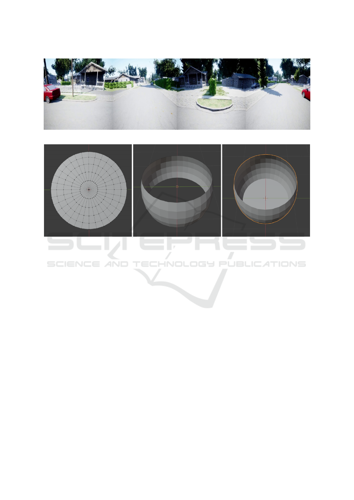
Figure 3: Generated panorama image with color correction applied.
Figure 4: Mesh model types for surround view. Left: Flat model. Middle: 360 horizontal model. Right: Bowl model.
to each three channels of the RGB color space sepa-
rately.
We use the five-point finite difference method to
solve the resulting discrete Poisson equation for all
pixels in the source domain, by using central differ-
ence formula to calculate intensity gradients. This re-
sults in a large and sparse system of linear equations
of size N ×N, where N is the total number of pixels in
the source domain (height times width of the source
image).
To solve this large and sparse system efficiently
we use AMGX library (Naumov et al., 2015), which
is a GPU accelerated solver library. Here we em-
ploy an algebraic multigrid solver with a block Jacobi
(Saad, 2003) smoother as a preconditioner for an iter-
ative Krylov solver, namely the Bi-Conjugate Gradi-
ent Stabilized (BiCGStab) algorithm (Van der Vorst,
1992).
Since we have sequences of images for each cam-
era (in a video setting), the corrections that should be
applied to source images on consecutive time steps
may be close to each other. To facilitate this, we use
the output of solver at current time step as an initial
guess for the solver of next time step. This way, the
solver can converge faster, helping the real-time per-
formance of the overall pipeline. To further enhance
the real-time performance, we calculate the intensity
correction of the source image in a down-scaled res-
olution. In our experiments we downscale source im-
ages with a factor of 0.25 so that the resulting linear
system is of size (N/16) × (N/16) instead of N × N.
Calculated corrections are then upscaled using bicu-
bic interpolation before applying them to the source
image of original resolution. The resulting panorama
image after color correction can be seen in Figure 3.
2.4 Mesh Generation and Texture
Mapping
Three types of mesh models have been used to gener-
ate surround view videos. We call them as flat model,
360 horizontal model, and bowl model. The first type
(flat model) is a flat circle with about 9 meters radius
which represents the flat ground. The second type
(360 horizontal model) is a cropped sphere which has
a radius of about 10 meters. This sphere is cropped
at the top and bottom sides to form an horizontal 360
nearly cylindrical shape. The third type (bowl model)
is the combination of first two types and represent the
surrounded environment of the car. Similarly Zhang
et al. (2014); Auysakul et al. (2017); Gao et al. (2017);
Tseng et al. (2015), have used equivalent mesh ob-
VISAPP 2022 - 17th International Conference on Computer Vision Theory and Applications
260
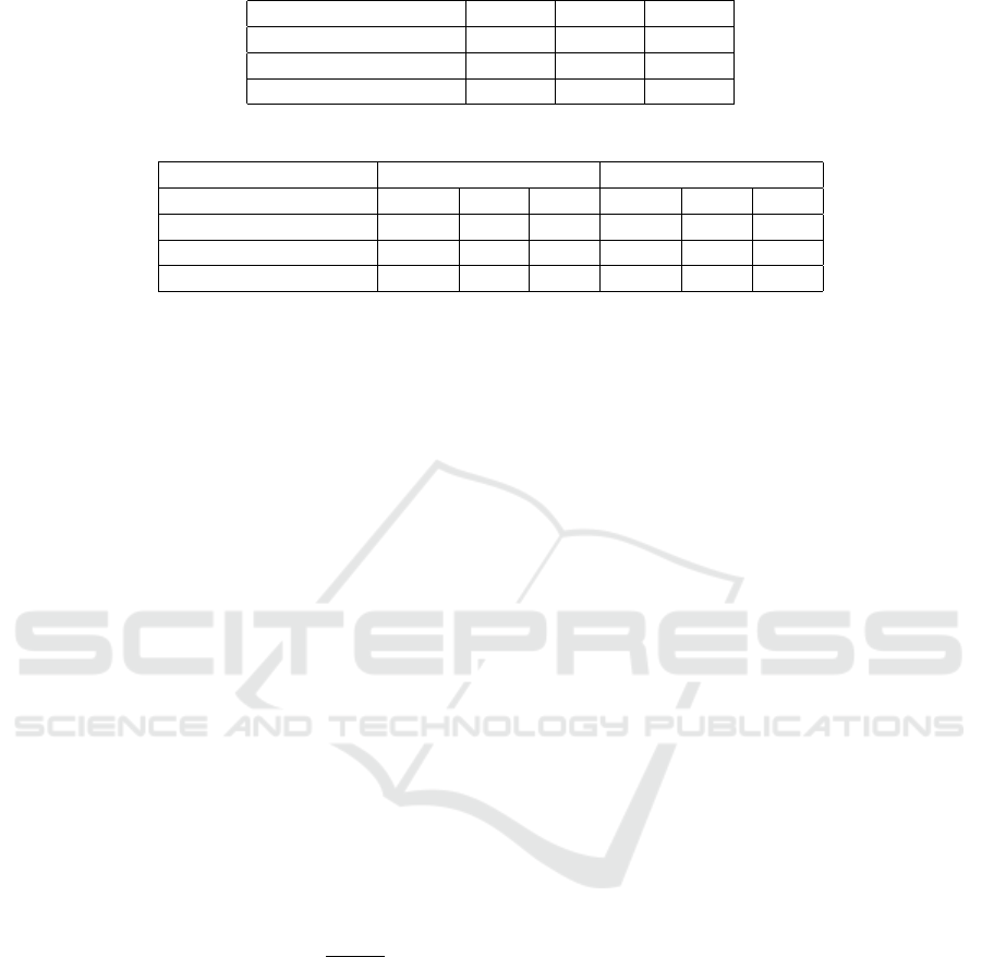
Table 1: Execution times on PC and embedded platforms.
Platform 1080p 720p 480p
PC 50 FPS 55 FPS 62 FPS
NVIDIA AGX Xavier 15 FPS 18 FPS 20 FPS
NVIDIA Xavier NX 9 FPS 11 FPS 12 FPS
Table 2: GPU and CPU utilizations on PC and embedded platforms.
GPU CPU
Platforms 1080p 720p 480p 1080p 720p 480p
PC 37% 35% 33% 70% 60% 35%
NVIDIA AGX Xavier 20% 18% 17% 51% 42% 33%
NVIDIA Xavier NX 26% 24% 22% 68% 56% 36%
jects that they call bowl mesh, hamburger mesh, ship
model, composite projection model etc.
The bowl model could be used for all purposes in-
cluding top view or 360 horizontal view but we use
three distinct models to decrease mesh-texture map-
ping computational complexity for each case. The
second reason is that the origin point x,y,z = (0,0, 0)
is at the bottom for flat and bowl models, but at the
center for 360 horizontal model. These centers affect
the texture mappings of the models. Figure 4 illus-
trates these three mesh models.
Mapping the textures of the mesh models is
straightforward. Figure 2 is a sample of prepared im-
age ready to texture the models. The texture images
are produced so that its covers a range of −π to +π in
horizontal +π/6 to −π/3 in vertical. These values are
used to map picture into mesh texture. This process
called as UV mapping. UV Maps range from 0 to 1
both on horizontal and vertical. In Equation 2, V is
the set composed by the vertices of mesh, u
0
, v
0
is the
angular coordinates of the vertex with respect to cen-
ter, and finally u,v are interpolated texture coordinates
between 0 and 1.
∀x,y,z ∈ V
u
0
,v
0
= atan(z/x), atan(y/
p
x
2
+ z
2
)
u,v = (u
0
− π)/(2π),2(v
0
− π/6)/π
(2)
3 EXPERIMENTS
The performance of the developed 3D surround view
pipeline is evaluated on both PC and NVIDIA’s em-
bedded platforms. For this purpose, we use synthetic
data acquired from AirSim simulator. AirSim pro-
vides physically and visually realistic simulation and
it is designed in a modular fashion. AirSim provides
realistic, customizable quadrotor and car models be-
sides several different sensors such as RGB camera,
depth camera, LIDAR, GPS. Configuration of the sen-
sors are highly customizable that one can change the
field of the view, image size, exposure of the camera
based on the requirements. These sensors can be at-
tached to the vehicle and at the desired positions.
In our experimental setup, we use 4 cameras with
a 100-degree field of view and each camera has a
90-degree rotation between each other and distributed
symmetrically to the top of the vehicle, as described
in Section 2.1. Figure 5 shows the resulting 3D sur-
round view from top view and horizontal view on
a bowl mesh model. In visualization environment,
a 3D vehicle model is placed in the center of the
mesh model. From the figure, it can be observed that
the proposed two-stage mapping and color correction
method provides a uniform scene with low distortion.
Table 1 shows the execution time of the method
both on PC and embedded platforms for different in-
put image resolutions. The method operates between
62.5 FPS and 50 FPS on a PC with Xeon E3-1230 pro-
cessor and NVIDIA GTX1070 GPU. Since we take
the advantage of GPU, proposed method runs in real-
time on NVIDIA embedded devices as can be seen
from the table. As input image resolution increases,
from 640× 480 to 1920 × 1080, the proposed method
maintains its real-time capability.
Table 2 shows the GPU and CPU utilizations for
different input resolutions. As can be seen from
the table, computation requirements of the proposed
method is in acceptable range for embedded systems.
It shows that the proposed surround view algorithm is
applicable to the systems which requires high-speed
and low power consumption.
Since there is not any benchmark dataset for qual-
itative and quantitative comparison for this problem,
studies on this topic have used their own setup for
evaluating their methods. Table 3 shows the com-
parison of the execution times on different platforms
of the similar methods, with the input image resolu-
tion if it is provided. From Table 2 and Table 3, it
can be observed that proposed method is superior to
A Real-time 3D Surround View Pipeline for Embedded Devices
261
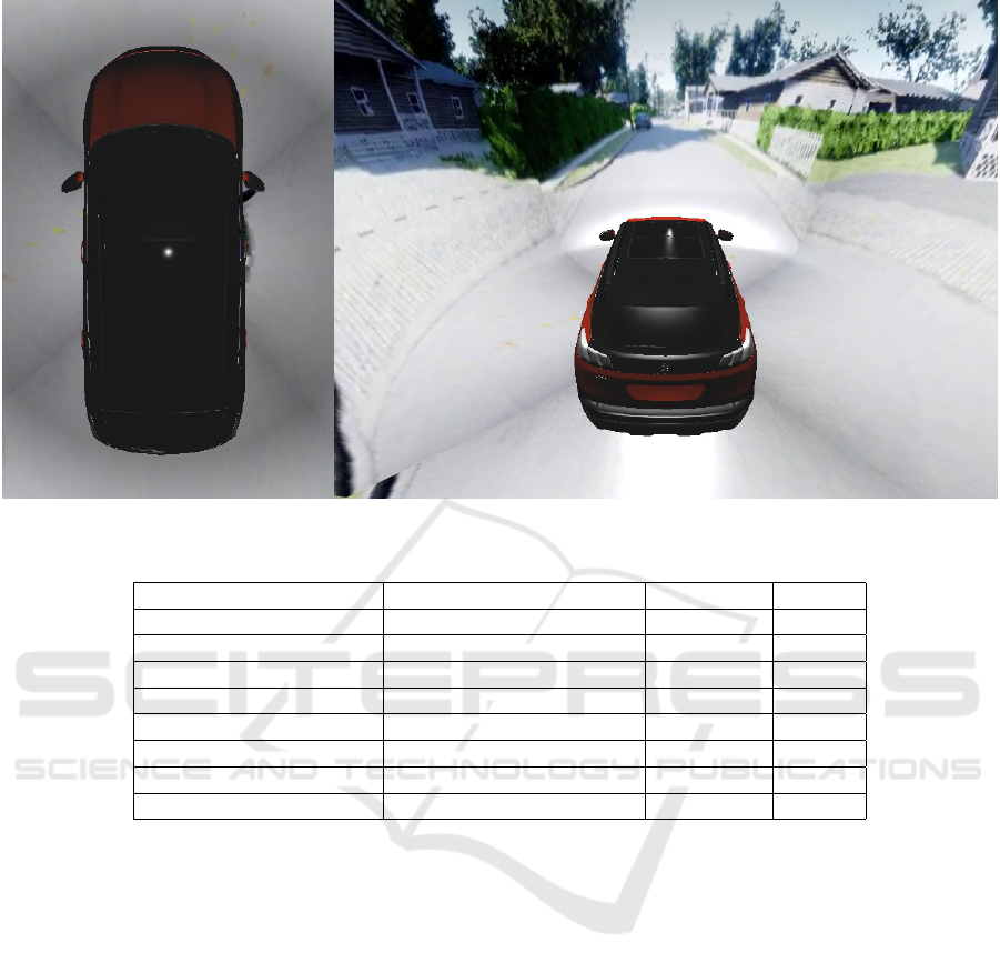
Figure 5: Generated sample 3D surround view using the bowl mesh from top and horizontal view.
Table 3: The comparison of the execution times of the methods on different platforms.
Method Platform Resolution FPS
Zhang et al. (2019) PC (2.7 GHz i5) - 20 FPS
Viswanath et al. (2016) TDA3x SoC 1280x800 30 FPS
Kashyap et al. (2017) PC (2.14 GHz Intel Atom) - 30 FPS
Chavan and Shete (2017) TDA2x SoC 1280x720 30 FPS
Baek et al. (2019) PC (3.3 GHz i9) 1920x1080 30 FPS
Baek et al. (2019) NVIDIA TX2 1920x1080 4 FPS
Ours PC (Xeon E3-1230) 1920x1080 50 FPS
Ours NVIDIA AGX Xavier 1920x1080 15 FPS
other methods both on PC and embedded platforms
at higher resolutions. This shows that our method
is more applicable where high-speed and low power
consumption is crucial compared to other methods.
4 CONCLUSION
In this study, we propose a 3D surround view sys-
tem for ADAS that works in real-time on embed-
ded devices. The proposed pipeline use four cam-
eras mounted on a vehicle. The method use a two-
stage mapping method and a low cost color correc-
tion algorithm to obtain a less distorted and uniform
panorama image. By projecting camera images onto
a bowl-shaped mesh model, the method enhance the
surveillance of the surroundings and provide a 360-
degree view of the surrounding environment. The ex-
perimental results show that the proposed surround
view pipeline is highly effective and efficient, in terms
of frame per second and resolution in embedded sys-
tems with low power consumption such as NVIDIA
Xavier NX.
Although the qualitative and quantitative evalua-
tions of the proposed method is conducted in a sim-
ulation environment, proposed method can be easily
adapted to real-world scenarios by only making sim-
ple modifications (such as camera calibration) in the
image acquisition step. Deployment of the proposed
surround view pipeline to any kind of vehicle (such as
armored vehicles) without any modification or with
minimal modifications is possible due to scalability
and extensibility of the method. As a future work, we
plan to integrate the system with virtual reality glasses
which will enhance the surveillance of surrounding
environment.
REFERENCES
Auysakul, J., Xu, H., and Zhao, W. (2017). Composite 3D
synthesis of video processing for around view mon-
VISAPP 2022 - 17th International Conference on Computer Vision Theory and Applications
262

itor applications. In 2017 4th International Confer-
ence on Systems and Informatics, ICSAI 2017, volume
2018-Janua, pages 1308–1312. Institute of Electrical
and Electronics Engineers Inc.
Baek, I., Kanda, A., Tai, T. C., Saxena, A., and Rajkumar,
R. (2019). Thin-plate spline-based adaptive 3D sur-
round view. In 2019 IEEE Intelligent Vehicles Sympo-
sium (IV), pages 586–593. IEEE.
Bier, E. A. and Sloan, K. R. (1986). Two-part texture map-
pings. IEEE Computer Graphics and applications,
6(9):40–53.
Chavan, S. and Shete, V. (2017). Three dimensional vision
system around vehicle. In 2017 IEEE International
Conference on Power, Control, Signals and Instru-
mentation Engineering (ICPCSI), pages 2639–2643.
IEEE.
Ehlgen, T. and Pajdla, T. (2007). Monitoring surrounding
areas of truck-trailer combinations. In International
Conference on Computer Vision Systems: Proceed-
ings (2007).
Gao, Y., Lin, C., Zhao, Y., Wang, X., Wei, S., and Huang,
Q. (2017). 3-D surround view for advanced driver
assistance systems. IEEE Transactions on Intelligent
Transportation Systems, 19(1):320–328.
Garc
´
ıa, J. D. E. (2015). 3D Reconstruction for Optimal
Representation of Surroundings in Automotive HMIs,
Based on Fisheye Multi-Camera Systems. PhD thesis,
Universit
¨
atsbibliothek Heidelberg.
Jia, J. and Tang, C.-K. (2005). Eliminating structure and
intensity misalignment in image stitching. In Tenth
IEEE International Conference on Computer Vision
(ICCV’05) Volume 1, volume 2, pages 1651–1658.
IEEE.
Kashyap, V., Agrawal, P., and Akhbari, F. (2017). Real-
time, quasi immersive, high definition automotive 3D
surround view system. In Proceedings of the Inter-
national Conference on Image Processing, Computer
Vision, and Pattern Recognition (IPCV), pages 10–16.
The Steering Committee of The World Congress in
Computer Science, Computer . . . .
Liu, Y.-C., Lin, K.-Y., and Chen, Y.-S. (2008). Bird’s-eye
view vision system for vehicle surrounding monitor-
ing. In International Workshop on Robot Vision, pages
207–218. Springer.
Naumov, M., Arsaev, M., Castonguay, P., Cohen, J., De-
mouth, J., Eaton, J., Layton, S., Markovskiy, N., Reg-
uly, I., Sakharnykh, N., et al. (2015). AmgX: A library
for GPU accelerated algebraic multigrid and precon-
ditioned iterative methods. SIAM Journal on Scientific
Computing, 37(5):S602–S626.
P
´
erez, P., Gangnet, M., and Blake, A. (2003). Poisson im-
age editing. In ACM SIGGRAPH 2003 Papers, pages
313–318.
Saad, Y. (2003). Iterative methods for sparse linear systems.
SIAM.
Sadeghi, M. A., Hejrati, S. M. M., and Gheissari, N. (2008).
Poisson local color correction for image stitching. In
VISAPP (1), pages 275–282.
Shah, S., Dey, D., Lovett, C., and Kapoor, A. (2018). Air-
sim: High-fidelity visual and physical simulation for
autonomous vehicles. In Field and service robotics,
pages 621–635. Springer.
Tseng, D.-C., Lin, Y.-C., and Chao, T.-W. (2015). Wide-
scoped Surrounding Top-view Monitor for Advanced
Driver Assistance Systems. Atlantis Press.
Van der Vorst, H. A. (1992). Bi-CGSTAB: A fast and
smoothly converging variant of Bi-CG for the solution
of nonsymmetric linear systems. SIAM Journal on sci-
entific and Statistical Computing, 13(2):631–644.
Viswanath, P., Chitnis, K., Swami, P., Mody, M., Shivalin-
gappa, S., Nagori, S., Mathew, M., Desappan, K., Ja-
gannathan, S., Poddar, D., et al. (2016). A diverse low
cost high performance platform for advanced driver
assistance system (ADAS) applications. In Proceed-
ings of the IEEE Conference on Computer Vision and
Pattern Recognition Workshops, pages 1–9.
Yu, M. and Ma, G. (2014). 360 surround view system with
parking guidance. SAE International Journal of Com-
mercial Vehicles, 7(2014-01-0157):19–24.
Zhang, B., Appia, V., Pekkucuksen, I., Liu, Y., Umit Batur,
A., Shastry, P., Liu, S., Sivasankaran, S., and Chit-
nis, K. (2014). A surround view camera solution for
embedded systems. In Proceedings of the IEEE con-
ference on computer vision and pattern recognition
workshops, pages 662–667.
Zhang, L., Chen, J., Liu, D., Shen, Y., and Zhao, S.
(2019). Seamless 3D surround view with a novel
burger model. In 2019 IEEE International Conference
on Image Processing (ICIP), pages 4150–4154. IEEE.
A Real-time 3D Surround View Pipeline for Embedded Devices
263
