
Mapping and Integration of Architecture and Modelling Frameworks
Qing Li
a
, Bohang Liang and Zhixiong Fang
Department of Automation, Tsinghua University, Beijing, China
Keywords: Architecture, Modelling, Mapping, Integration.
Abstract: Architecture, methodology and system modelling are systems engineering tools to understand, design,
develop, implement and integrate complex systems, software and enterprises. In order to solve the problem
of complex system integration, Zachman Framework, CIM-OSA, GERAM, FEAF, DoDAF, TOGAF and
other architectures have been developed. Model has become the main means of system analysis and design,
and gave birth to model-based systems engineering (MBSE). There are several methodologies of MBSE, such
as Harmony, Magic Grid and so forth. Therefore, it is necessary to develop a general architecture and
modelling framework to support models and systems, software, enterprise integration based on different
architecture and methodologies. This paper presents a General Architecture Framework and a relative General
Modelling Framework (GMF). GAF provides tools and methodology of model-based systems engineering
(MBSE) to systems design and development. GMF involves a set of models and methods to describes different
aspects of a system. The paper also discusses the mapping and integration relationship between GAF, GMF
with mainstream architecture and modelling frameworks.
1 INTRODUCTION
Architecture, methodology and modelling methods
are effective ways to analyse systems, software and
enterprises (SSE). In the past forty years, experts from
different professional domains committed themselves
in the study of architecture, and produced a set of
significant works. including Zachman Framework,
CIM-OSA (computer integrated manufacturing open
system architecture), PERA (Purdue enterprise
reference architecture), ARIS (architecture of
integrated information system), GERAM (generalised
enterprise reference architecture and methodology),
FEAF (federal enterprise architecture framework),
DoDAF (department of defence architecture
framework), TOGAF (the open group architecture
framework), UAF (Unified Architecture Framework).
GEAF (Gartner’s Enterprise Architecture
Framework), ESA-AF (European Space Agency-
Architectural Framework), etc. These are all
architectures with great international influcence and
have a wide range of applications in many fields.
Many of them have some extended version when
applied in different field. Such as TEAF (Treasury
Enterprise Architecture Framework, based on
a
https://orcid.org/0000-0002-6013-1921
Zachman Framework). Base on DoDAF, many
organization develop their own extended defense-
based architecture framework: MODAF (British
Ministry of Defence Architecture Framework,
developed by The UK Ministry of Defence), NAF
(NATO defense standrad), AGATE (the France DGA
Architecture Framework).
In some specific fields, there are many proprietary
frameworks, such as RASDS (Reference Architecture
for Space Data System) in the space industry
(CCSDS, 2016), AUTOSAR (Automotive Open
System Architecture) in the automotive industry.
At the meanwhile, international standards such as
ISO 15704 (ISO, 2005), 19439 (ISO, 2006), 19440
(ISO, 2007), and 42010 were published to underpin
the identification of requirements for models, the
establishment of modelling framework and the
formation of modelling methodology respectively.
ISO 42010 proposed a standardized system
description method centered on architecture
description, architecture framework, architecture
description language (ISO, 2011).
In additional to systems, software, enterprises
(SSE) architecture, modelling methods and languages
have undergone rapid evolutions in order to satisfy the
216
Li, Q., Liang, B. and Fang, Z.
Mapping and Integration of Architecture and Modelling Frameworks.
DOI: 10.5220/0010740100003062
In Proceedings of the 2nd International Conference on Innovative Intelligent Industr ial Production and Logistics (IN4PL 2021), pages 216-226
ISBN: 978-989-758-535-7
Copyright
c
2021 by SCITEPRESS – Science and Technology Publications, Lda. All rights reserved

demanding analysis requirements for complex
systems. Modelling languages such as IDEF (integra-
tion definition) series modelling languages (including
IDEF0, IDEF1x, IDEF3, IDEF5, et. al.), UML
(unified modelling language, which includes multiple
views and diagrams), DFD (data flow diagram), ERD
(entity relationship diagram), EPC (event process
chain), BPMN (business process modelling notation),
UPDM (Unified Profile for DoDAF/MODAF,) BPEL
(business process execution language), Gellish
(Generic Engineering Language, a textual modelling
language), SoaML (Service-oriented architecture
Modeling Language), ESL (Energy Systems
Language), AADL (Avionics Architecture
Description Language), EAST-ADL (designed for
complement AUTOSAR), Petri net and the newly
developed ArchiMate and SysML are gaining
increasing popularity in the field of system modelling.
Among them, UML has a wide range of influence in
the field of information system development and
software engineering. As an extension of UML,
SysML is widely used in system engineering. In
ISO/IEC 19514:2017, SysML v1.4 was set as an
International Standard (ISO, 2017).
The complex systems, software, enterprises
design and development process is now evolving
while modern industry is trying to free itself from
tedious paperwork. Modeling is an effective way to
solve the design and research problems of complex
management and technology integration systems. At
present, industrial design and development is facing
an important mode-change, which is that model-based
systems engineering (MBSE) is replacing
Traditional/Text-based Systems Engineering (TSE).
The International Council on Systems Engineering
(INCOSE) proposed MBSE in "Systems Engineering
Vision 2020 " (INCOSE, 2007). It aims at enabling
the modeling method to support the whole process of
system design, including requirements validation,
design, analysis, verification and validation, starting
from conceptual design and covering the whole life
cycle of product design (Friedenthal et al., 2007;
Haskins, 2011). NASA, Boeing, Lockheed Martin,
and Airbus are all actively practicing and promoting
MBSE. At the same time, MBSE has entered
petrochemical, construction, healthcare, smart city
and other industries and fields. In 2014, INCOSE
published "Systems Engineering Vision 2025 "
(INCOSE, 2014). In this report, INCOSE stated that
in the future, the application of MBSE will expand
from tradition fields to engineering, natural and social
fields.
More and more system development projects
include different architecure, methodologies and
modelling methods. How to integrate these
architecture, methodologies and modelling methods
becomes a big challenge.
This paper presents a General Architecture
Framework and a relative General Modelling
Framework (GMF). GAF provides tools and
methodology of model-based systems engineering
(MBSE) to systems design and development. GMF
involves a set of models and methods to describes
different aspects of a system. The paper also discusses
the mapping and integration relationship between
GAF, GMF with mainstream architecture and
modelling frameworks.
The paper is structure as follows. In section 2. A
General Architecture Framework is proposed,
including the corresponding General Modelling
Framework. Section 3 discusses the mapping
relationship between GAF (General Architecture
Framework) and other mainstream architectre. In
section 4, the General Modelling Framework is
compared with other modelling architectures. Finally,
section 5 puts forward the conclusions.
2 GENERAL ARCHITECTURE
FRAMEWORK (GAF) AND
GENERAL MODELLING
FRAMEWORK
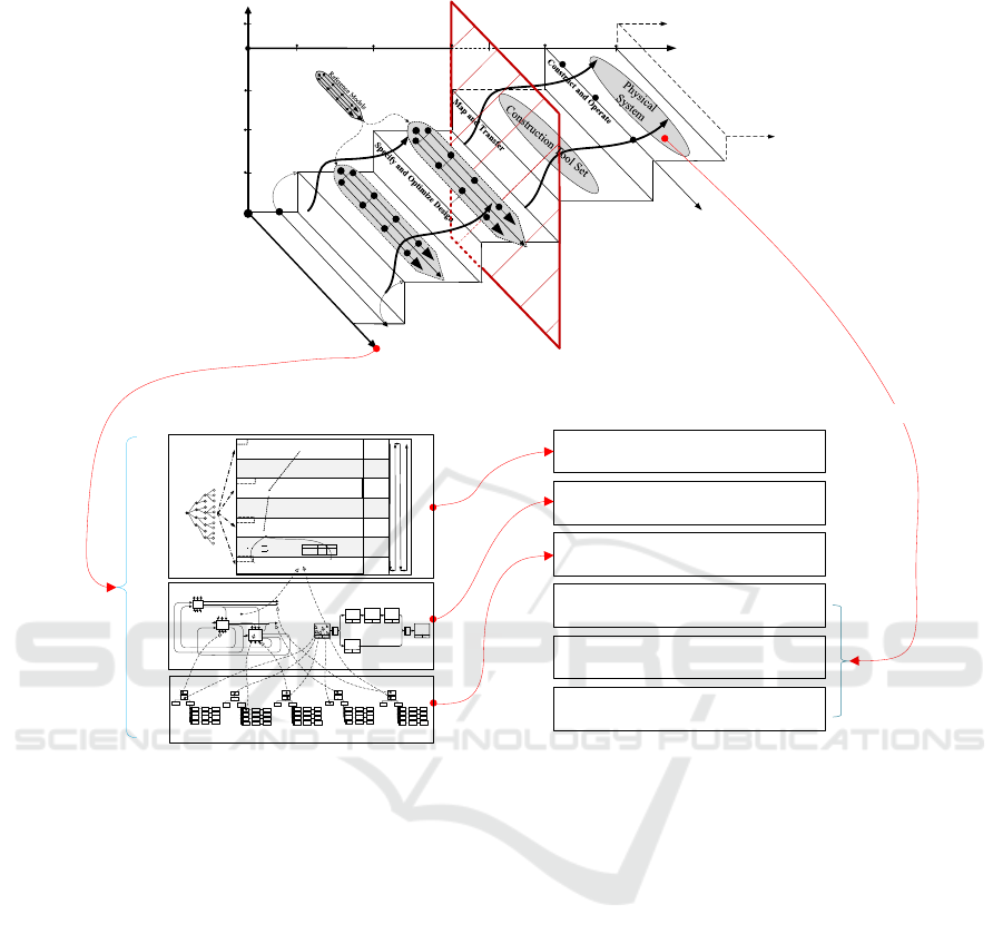
The General Architecture Framework (GAF) is a
system, software, enterprise (SSE) architecture
framework raised by Qing (2007). As shown in the
top of Fig.1, view, lifecycle and realization, these
three axes form the basis of GAF.
View: The axis pays attention to the structure of
the system from static and dynamic aspects. It
includes seven views: Function View,
Organization View, Resource View, Information
View, Product View, Process View and
Economic/Performance Evaluation View, whose
relationship is described in more detail in the left
bottom of Fig.1.
Lifecycle: The lifecycle of GAF is based on the
project lifecycle, with an additional segment
named operation and maintenance. The project
lifecycle just starts from project definition and
ends up with implementation. There is a difference
because architecture can greatly help an integrated
system in tracking, modification and optimization,
when the system is operating. And the modelling
methods of architecture are equally important for
system operation.
Mapping and Integration of Architecture and Modelling Frameworks
217
Performance Reference Model
Business Reference Model
Data Reference Model
Application Reference Model
Infrastructure Reference Model
Security Reference Model
GAF Modelling Framework and Views
GAF Analysis, Design and Implementation
Framework (Based on Federal Enterprise
Architecture Framework)
General Architecture Framework (GAF)
Reference Architecrure
Technical Realization
Conceptural
Defination
As-Is
Models
To-Be
Models
Technical
Specification
Technical
Realization
Project Life Cycle
Stepwise Realization
Subsystems
Human &
Organization
Implementation
Detailed Design
Preliminary Design
Analysis
Project Definition
Views
Information
Goal
Computer Aided
Software Engineering
Tools, Workflow
Model, Etc.
Operation &
Maintenance
Continuous
Improvement
Structural
Behavioral
Performance
(1)
(2)
(3)
(4)
(5)
Manufacturing
System Evaluating and Economic
Analyzing Structure
Goal
Indic ators
Factors
Enterpris e competitive C apacity
Impro vement a nd Ent erpri se Succ ess
Elements
Time Cos t Qu ality Servi ce
Envir onment Feasibi lity
Software Development Cost
Putnam
Model
COCOMO
Model
L
Code Lines
td
Project duration(Year)
K
Workload of software developers a nd
maintenanc e personnel (Man/Year)
Ck is constant
a,b,c and r are constants based on the pr oject type.
S
is code lines (Kilo-line)
E is work load ( man/per mon th)
D is pr oject durat ion ( month )
Physical algorithm,
linear/nonlinear fit
Calcul ational methods
Weighted
Sum,geometrical
methods,vector
space, o ther
in tegr at in g met ho d s
AHP, ANP,
Evaluation,Decision
Suppor ting Met hods
Evaluatin g
Sturcture
System Implementation
Target Decomposit ion
System Analysis
System Monitor and Control
3
4
3
1
tdKCkL
43
3
t
d
Ck
L
K
4
1
3
3
)(
K
C
k
L
td
15
1i
i
c
fSrE
Softwar e Pro je ct Typ e
rC
A
B
C
3.2
3.0
2.8
1.05
1.12
1.20
System Behavior
Structures
2
3
1
2
4
1
6
5
X X
3
Functional
Relationship
Scheduling and Logical
Relationship
System Static
Structures
Organization
Structure
Function
Structure
Resource
Structure
Information
Structure
Product/Service
Structure
Calcul ational methods
Calculational met hods
Figure 1: General architecture framework and general modelling framework.
Realization: This axis reflects how to use the
methodology of the architecture. Architecture
methodology uses models instead of a large
number of words to describe all aspects of the
system. That is to say, this axis shows how to use
the modelling method to accomplish system
analysis, design, operation and maintenance.
Firstly, get the AS-IS models. In this stage, the
current system is descripted in several views
according to the division of views in the first axis,
and these descriptions can form AS-IS models of
great coherence with the help of other SSE
modelling methods. Secondly, get the TO-BE
models. In this stage, the problems and
contradictions of the current system should be
discovered through the analysis of the AS-IS
models. These problems should be solved step by
step according to their importance and urgency.
The TO-BE models should provide a solution on
the principle and abstract layer to meet the
requirement, which is also called preliminary
design. Thirdly, conduct detailed design. In this
stage, constructing tools can help translate the
requirement embodied by various models into
design specification in three concrete domains (or
called subsystems). The new real system can be
built. What should be emphasized is that the
mapping relationship between the design
specification and the description of models (or
views) is “multi-to-multi”. Fortunately, many tools
or tool sets have been developed to manage this
mapping relationship, such as CASE tool,
Workflow Management Technique, etc.
From this architecture, we can know that the
identification and construction of the system are
gradually evolving. We do different things with
different methods in different stage, and what we do
in the last stage will affect what to do and how to do
in the next stage. In the conceptual design stage, it is
important to determine the strategic goals of the
enterprise, because it determines the usefulness of the
system, that is, what it is used to do and what
EI2N 2021 - IFAC/IFIP International Workshop on Enterprise Integration, Interoperability and Networking
218

requirements it meets. Sequentially, according to the
requirements and purposes of the system, we can find
some problems that must not exist more easily after
describing the current situation of the enterprise from
the aspects of organization, resource, information,
product, function and operating process and then
infrastructure and operation mechanism. Then we
improve these problems and the target system will be
constructed and its various views can be formed well.
This is a specifying and optimizing process.
When describing the target system, we can apply
many modelling methods not just the method of view
description to characterize the system much more
comprehensively. After the model is built, it is
transformed into the technical guidance of building
the system through the construction tool set, so as to
form a real system. Since the system description is the
guidance for system construction, it can certainly be
used as the reference object for system operation to
modify and optimize the actual system.
As shown in the left bottom part of Fig.1., the
General Modelling Framework (GMF) is divided into
three layers: performance and evaluation structure
layer, system behaviour /dynamic structure layer and
system static structure layer. Each layer represents an
aspect of the enterprise. The specific contents are as
follows:
System static structure layer: models at which
define the static structure of the enterprise,
including organizational structure, resource
structure, data / information structure, product /
service structure and functional structure, define
the existence of the enterprise and answer the
question of what the system is.
System behaviour / dynamic structure layer:
models at which describe the logic, sequence and
relevant characteristics of the whole system,
combine the elements defined by the static
structure layer to define the model of enterprise
operation mechanism.
System performance structure layer: model at
which define the target of the system, the related
performance indicators and measurement methods.
The models of system static and behaviour layer
describe the system structure and operation
mechanism constrained by system objectives, which
constitute the basis of performance analysis. The
system performance structure layer is based on the
system structure and behaviour layer to provide
modelling form for the performance aspect of SSE,
learns from the existing model content and establishes
analysis methods to inform decision makers. Under
the guidance of SSE strategy and performance
evaluation mechanism, a network description with
structural components is formed according to the
interrelated (input, output, control, mechanism) or
sequential logical relationship. Because performance
evaluation is very important for decision-makers and
stakeholders in the early stage of SSE project,
performance-related modelling has become one of the
key parts in the field of enterprise modelling. For
example, ISO 22400 was developed for automation
systems and integration - key performance indicators
(KPIs) for manufacturing operations management
(ISO, 2014); ISO/IEC 42030 was developed for
Systems and Software Engineering – Architecture
Evaluation. Evaluation modelling and analysis can
point out the optimization direction of enterprise
development (ISO, 2005). In ISO 15704 Amd 2005,
AHP/ANP (Analytical Hierarchy/Network Process)
method and Activity Based Costing (ABC) are
proposed to facilitate the decision-making process on
the multiple criteria’s aspect of system integration
justification.
In fact, various structures are interrelated.
Therefore, the structured units in all aspects of the
architecture can be used as the focus associated with
other units, reflecting that the view is the embodiment
of a certain aspect of the enterprise system. For
example, if there is no description of the production
process, the product structure cannot reflect the
panorama of the product; without the constraints of
the internal operation mechanism of the organization,
the organizational structure cannot well reflect the
operation of the enterprise; the resource structure only
reflects the existence and quantity, and what really
affects the operation of SSE is the dynamic resource
allocation and utilization.
The right bottom part of Fig. 1 is GAF analysis,
design and implementation framework based on
Federal Enterprise Architecture Framework (FEAF)
2.0. When we start a project, the first thing we should
do is to analyse the performance of the system, which
may also be a software or an enterprise. Based on the
performance analysis of existing system and required
system, we can design a business model that meets the
requirements by transforming, deleting and
innovating the existing business processes. And then
we should describe various business processes’
functional and logical relationship. In order to support
the proper operation of the business, we need to
another model to explain what functional components
are needed, what kind of team organization people
will use to participate, what resources and
information will be used and what products or
services are produced in various business processes.
After analysis and design, it’s time to implement the
Mapping and Integration of Architecture and Modelling Frameworks
219

design scheme. During in the process of
implementation, we need construction tools like
CAD/CAE to transfer designed system to physical
system.
This part points out SSE modelling can be
combined with its technical architecture.
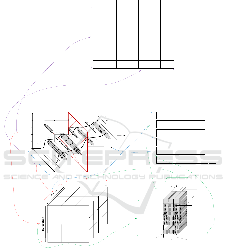
3 MAPPING BETWEEN GAF AND
OTHER ARCHITECTURES
Computer Integrated Manufacturing Open System
Architecture (CIM-OSA), FEAF, and Generalised
Enterprise Reference Architecture and Methodology
(GERAM) and Zachman Framework are four
mainstream Architecture Frameworks. They or some
of their contents can be mapped to GAF, as shown in
Fig. 2. And we can see there is also a mapping
relationship in these mainstream Architecture
Frameworks
CIM-OSA is developed by ESPRIT Consortium
AMICE (1993) for enterprise integration. It includes
three dimensions: stepwise generation, stepwise
derivation and stepwise instantiation. The derivation
dimension includes three steps: requirements
definition, design specification and implementation
description. This dimension shows three stages in the
lifecycle of Computer Integrated Manufacturing
System, without the part of realization and operation.
In each stage of the derivation dimension, we need
suitable models from different views in the generation
dimension. The second dimension includes four
views: function view, information view, resource
view and organization view, in which there is a
progressive relationship. The functional model builds
a functional structure to meet strategic goals of the
enterprise. The information model and resources
model introduce what information and resources are
required in the functional model and describe their
relationship to each function. The organization model
describes how people participate to ensure the
realization of functions and their responsibility for
each function. The generation dimension is based on
function rather than process, and it lacks behavioral
structure. The instantiation dimension reflects the
process from general to specific. It includes three
layers: generic building blocks, partial models and
particular model. For example, generic building
blocks may be used for every enterprise, partial
models may be used for enterprises in specific domain
and particular model may be customized for a specific
enterprise.
FEAF is an enterprise architecture proposed by
the U.S. Office of Management and Budget. The first
version was published in 1999 and it (CIOC 2001)
believes that the business drivers and design drivers
will promote the transformation of the enterprise from
the existing architecture to the target architecture. In
such circumstance, we should carry out
transformation of business architecture, data
architecture, application architecture and technology
architecture under the guidance of the enterprise
strategic directions, vision and principles. FEAF 2.0
was released in 2013 and different from the first
version. FEAF 2.0 (OMB 2013) includes 6 reference
models and they have a progressive relationship. The
performance reference model reflects the strategic
goals of the enterprise, so it determines what kinds of
business are needed and what benefits they can bring
to the enterprise. A large amount of data will be
generated and used in the business. In order to do
business better, a data reference model is needed to
manage data by detailed description and correct
classification. The application reference model
describes what kind of software, web interface or
digital platform to store, analyze, encrypt, use and
destroy data. And the infrastructure reference model
describes what kind of information infrastructure
these applications should be deployed on, network,
communication facilities, servers and so on. Security
is so important that the security reference model is
involved in every other aspect. The security reference
model describes the risks in each of the other models
and what kind of safety accidents will be caused by
these risks and then losses caused by these accidents.
We can use the method of risk analysis to evaluate
whether the risk is tolerable, and then make suitable
countermeasures.
GERAM was published by IFAC and IFIP in the
1990s ( P. Bernus, and L. Nemes, 1994). It is included
in the ISO 15704 that try to form a generalized
enterprise reference architecture and methodology to
realize interoperate between different architecture.
This reference architecture also includes three
dimensions: life-cycle phases, views and instantiation.
The life-cycle phases dimension includes seven
phases: identification, concept, requirements, design,
implementation, operation and decommission. In
identification phase, we can identify any business
process or entity and it environment, so we can get the
conceptual model of the analyzed object. Then we can
analyze the current situation through the conceptual
model, so as to find out what kind of service we
should provide for customers and what changes we
should make in management and control. These
improvements put forward new requirements at
EI2N 2021 - IFAC/IFIP International Workshop on Enterprise Integration, Interoperability and Networking
220

present. In order to solve problems and meet
requirements, we need to design the whole system
architecture in preliminary design phase, including
operation process and functional module, and then
determine the physical manifestation of the system
architecture, including software and hardware. In
implementation phase, the designed system will be
transformed into a real system with the help of
resource model, organization model, information
model and function model. In operation phase, the
real system consumes resources and produces
products or provide service, following the operation
process designed in preliminary design phase. In
decommission phase, the real system is at the end of
its life, and it will be scrapped and recycled according
to it situation. The instantiation dimension is exactly
the same as that in CIM-OSA. The views dimension
has different views depending on the present lifecycle
phase. For example, it includes software and
hardware views in preliminary design phase, but
resource, organization, information and function
views in implementation phase.
The Zachman Framework was proposed by John
Zachman (1987) for the first time and has been
expanded for many times. One ( John F. Sowa and
John Zachman, 1992) of those expanded frameworks
is shown in Fig.2. It has only two dimensions, but may
be the first popular framework and is the basis of
many other popular enterprise architectures. The
horizontal dimension includes six important views to
ask questions about the system. They are data,
function, network, people, time, motivation. The
vertical dimension includes six roles involved in the
system and what they are concerned about in their
perspectives. They are planner, owner, designer,
builder, programmer, user. If every role’s concerns
are clear in six views, they know what data they need,
how it works, where it happens, who engage, when
various works should be done and why they do like
so, then the system can be constructed easily and
quickly.
CIM-OSA’s three dimensions are related to
GAF’s view, lifecycle dimensions and reference
models. The generation dimension includes
organization, resource, function, information views,
exactly four of the seven views in GAF, which
represent the static structure of an enterprise. The
derivation dimension includes requirements
definition, design specification and implementation
description, which are preparations to build a real
system. And they can be related to the front part of
GAF’s lifecycle dimension. Instantiation dimension
reflects the process from general blocks to particular
models. This is also how we construct reference
architecture and reference models in the realization
axis in GAF, from overall structure to models in
different views. CIM-OSA and GAF show the same
idea that the integrated enterprise should be modelling
in different views and the process of system definition
and construction is gradual and evolutionary.
The top three layers of FEAF 2.0 are directly
related to GMF. The performance model and the
performance & evaluating structure are similar but
have different emphases. One establishes a standard
performance metrics framework but the other one
gives calculation methods and evaluating structure
besides simplified performance metrics. The business
reference model and the system behavior structure
both describe operation process of the system. The
data reference model is similar to information
structure in the system static structure. The bottom
three lays in FEAF 2.0 form the technical architecture
of a real information system, corresponding to the
process of technical realization in the axis of stepwise
realization in GAF. They both describe how to use
things in cyber and physical world to support the
implementation of the real system. But security is not
emphasized in GAF.
The key concepts and factors of GERAM can be
mapped to GAF. The lifecycle axis of GAF is similar
to the life-cycle dimension of GERAM, but without
identification. The instantiation dimension of
GERAM is just what it is in CIM-OSA, and can be
also mapped to reference model of GAF. The views
dimension in both architectures are similar. The
difference is that views changes with the different
lifecycle phases in GERAM but remains the same in
GAF. Besides, GAF doesn’t have machine views and
management views.
Different roles in Zachman Framework are people
engaging in different lifecycle phases, and different
views are also similar to views in GAF. So the
horizontal dimension and the vertical dimensions
correspond to the views dimension and the lifecycle
dimension
Fig. 2 presents mapping relationships of these
architectures to GAF. But these architectures have
mapping relationships with each other. The
instantiation, generation and derivation dimensions in
CIM-OSA can be mapped to the instantiation, views
and life-cycle phases dimensions in GERAM. The top
three layers and the bottom three layers of FEAF 2.0
are mapped to views in the first six phases of the life-
cycle dimension and machine & human views in
GERAM respectively.
Other architectures can also be mapped to GAF and
realized mutual mapping based on GAF.
Mapping and Integration of Architecture and Modelling Frameworks
221
General Architecture Framework (GAF)
Reference Architecrure
Technical Realization
Conceptural
Defination
As-Is
Models
To-Be
Models
Technical
Specification
Technical
Realization
Project Life Cycle
Stepwise Realization
Subsystems
Human &
Organization
Implementation
Detailed Design
Preliminary Design
Analysis
Project Definition
Views
Information
Goal
Computer Aided
Software Engineering
Tools, Workflow
Model, Etc.
Operation &
Maintenance
Continuous
Improvement
Structural
Behavioral
Performance
Manu facturin g
Organization
View
Organization
View
Organi zation
View
Resource
View
Resource
View
Resource
View
Information
View
Information
View
Information
View
Function
View
Function
View
Function
View
Particular
Requirements
Definition
Model
Generic
Requirements
Definition
Building
Blocks
Partial
Requirements
Definition
Models
Particular
Design
Specification
Model
Generic
Design
Specification
Building
Blocks
Generic
Implementation
Description
Building
Blocks
Partial
Design
Specific ation
Models
Partial
Implementation
Description
Models
Particular
Implementation
Description
Model
Instantiation
Process / Life cycle
Views / models
Model development
& model base
CIM-OSA
Performance Reference Model
Business Reference Model
Data Reference Model
Application Reference Model
Infrastructure Reference Model
Security Reference Model
Federal Enterprise Architecture Framework
Security Reference Model
Technical architecture
Views / models
{
Hardware
Software
Instantiation
Management
Customer service
Human
Machine
Life-cycle
phases
Views
}
}
}
Generic
Partial
Particular
{
}
Design
Preliminary
design
Detailed
design
Identification
Concept
Implementation
Operation
Decommission
Requirements
Resource
Organisation
Information
Function
}
Reference Architecture Particular Architecture
according
Subdivision
to genericity
according to purpose
Subdivision
of activity
according to physical
manifestation
Subdivision
according to
Subdivision
model content
to means of
Subdivision according
implementation
and control
{
{
{
{
{
{
GERAM
Zachman
Framwork
DATA
What
FUNCTION
How
NETWORK
Where
PEOPLE
Who
TIME
When
MOTIVATION
Why
Objective/Scope
(contextual)
Role: Planner
List of things
important in
the business
List of
Business
Processes
List of
Business
Locations
List of
important
Organizations
List of Events
List of Business
Goal & Strategies
Enterprise
Model
(conceptual)
Role: Owner
Conceptual
Data/Object
Model
Business
Process
Model
Business
Logistics
System
Work Flow
Model
Master
Schedule
Business Plan
System Model
(logical)
Role: Designer
Logical Data
Model
System
Architecture
Model
Distributed
Systems
Architecture
Human
Interface
Architecture
Processing
Structure
Business Rule
Model
Technology
Model
(physical)
Role: Builder
Physical
Data/Class
Model
Technology
Design Model
Technology
Architecture
Presentation
Architecture
Control
Structure
Rule Design
Detailed
Representation
(out of context)
Role:
Programmer
Data
Definition
Program
Network
Architecture
Security
Architecture
Timing
Definition
Rule speculation
Functioning
Enterprise
Role: User
Usable Data
Working
Function
Usable
Network
Functioning
Organization
Implemented
Schedule
Working Strategy
Figure 2: Mapping between GAF and other architecture.
4 MAPPING BETWEEN GMF
AND OTHER MODELLING
ARCHITECTURE
There are plenty of SSE modelling languages and
methods. In any SSE projects, multiple modelling
methods will be included in. GMF can be used to
organize related modelling methods sets and relative
models.
FEAF 2.0 is widely used in the field of
government administration and enterprise
informatization.
As shown in Fig. 3, the bottom three layers of
FEAF 2.0 are related to technical realization, they are
mapped to SSE realization of GAF. The other three
EI2N 2021 - IFAC/IFIP International Workshop on Enterprise Integration, Interoperability and Networking
222
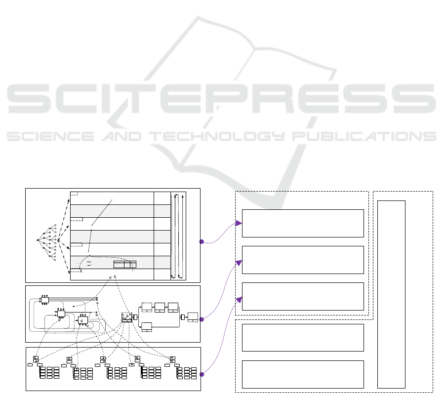
layers: Performance reference models, Business
reference models, Data reference models, are related
to business.
Data reference models are part of System Static
Structure. Business reference models are related to
enterprise behaviour, which is mapped with Systems
Behaviour Structure of GME.
The initial FEAF just had four layers. In order to
describe strategic goals of business and evaluate its
performance, it added Performance reference models.
Performance reference models are the external
manifestation of the enterprise. This layer is mapped
with Performance & Evaluation Structure.
Thus, models in the analysis and design stage of
FEAF 2.0 can be mapped to GMF directly. They have
the same hierarchical structure.
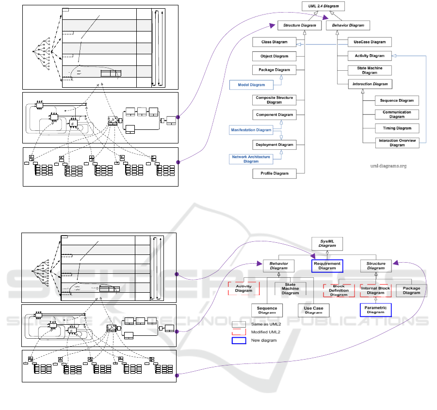
UML has a wide range of influence in the field of
system development and software engineering. It is a
general visual modelling language for intuitive,
clarified, componentized and documented software
system products. This is benefited from its various
diagrams which help to describe system excessively.
As shown in Fig. 4, UML model system contains
many diagrams. UML divided them into two parts:
Structure Diagram and Behaviour Diagram. For
example, Class Diagram represents the classes in the
system and the relationship between classes.
Deployment Diagram reflects the physical
architecture of the software and hardware in the
system. They are both used to described the static
structure of system, which mapped with System
Static Structures of GMF. Activity Diagram reflects
the flow from one activity to another in the system.
Sequence Diagram represents the time sequence of
sending messages between objects. They are both
describe the dynamic behaviour of system which
mapped with System Behaviour Structures of GMF.
From the above comparation, it can be seen that
both the GFM and UML model system contain views
of structure and behaviour, and the GMF emphasizes
the importance of performance modelling.
UML is mainly used for software system
engineering, and later found that it can be extended to
other system engineering. Therefore, OMG and
INCOSE selected some diagrams from UML and
added some more general diagrams to form the
SysML(L. Delligatti. 2013).
As shown in Fig. 5, the diagrams of SysML can
be divided into three parts: Behaviour Diagram,
Requirement Diagram and Structure Diagram. There
are two new diagrams: Requirement Diagram and
Parametric Diagram. The addition of them is an
important development from UML to SysML.
Requirement Diagram shows the system
requirements and their relationships with other
elements. Parametric Diagram is part of structure
diagram. It is useful for performance and quantitative
analysis. These two diagrams can help refine
requirements during the development process and
then be used for function analysis and design
synthesis. Both of the new diagrams are related to
performance of the system which is mapped with
Performance & Evaluation Structure of GMF.
Performance reference models
Business reference models
Data reference models
Application reference models
Infrastructure reference model
Security reference model
Federal Enterprise Architecture
Framework
GAF Modelling Framework and Views
Performance & Evaluation Structure
Goal
Indic ators
Factors
Enterp rise competitive Capa city
Improvement and Enterprise Success
Elements
Time Cost Quality Service
Environment Feasibili ty
Software Develop ment Cost
Putnam
Model
COCO MO
Model
L
Code Lines
td
Project duration(Year)
K
Workload of software developers and
maintenance personnel (Man/Year)
Ck is constant
a,b,c and r are constants based on the project type.
S
is code lines (Kilo-line)
E is work loa d (man/per month)
D is project duration (month)
Physical algorithm,
linear/ nonlinear fit
Calculat ional methods
Weighted
Sum,geometrical
methods,vector
space, other
in tegr ati ng met hod s
AHP, ANP,
Evaluation,Decision
Supp or ting Me thods
Evaluating
Sturcture
System Implementation
Target Decompositi on
System Analysis
System Monitor and Control
3
4
3
1
tdKCkL
43
3
tdC
k
L
K
4
1
3
3
)(
K
C
k
L
td
15
1i
i
c
fSrE
Software Project Type
rC
A
B
C
3.2
3.0
2.8
1.05
1.12
1.20
System Behavior
Structures
2
3
1
2
4
1
6
5
X X
3
Functional
Relationship
Scheduling and Logical
Relationship
System Static
Structures
Organization
Structure
Function
Structure
Resource
Structure
Information
Structure
Product/Service
Structure
Calculat ional methods
Calculat ional methods
Figure 3: GMF and FEAF 2.0.
Mapping and Integration of Architecture and Modelling Frameworks
223
UML2.4 Framework
GAF Modelling Framework and Views
Performance & Evaluation Structure
Goal
Indicators
Facto rs
Enterprise competitive Capacity
Improvement and Enterprise Success
Elements
Time Cost Quality Service
Environment Feasibi lity
Software Development Cost
Putna m
Model
COCOMO
Model
L
C od e Li ne s
td
Project duration(Year)
K
Workload of software developers and
maintenance personnel (Man/Year)
Ck is constant
a,b,c and r are constants based on the project type.
S
is co de line s ( Kil o-l ine)
E is w ork load (man/p er mont h)
D is project duration (month)
Physical algorithm,
linear/nonlinear fi t
Calculational methods
Weighted
Sum,geometrical
methods,vector
space, other
integrating methods
AHP, ANP,
Evaluation,Decision
Supporting Methods
Evaluating
Sturcture
System Implementation
Target Decomposition
System Analysis
System Monitor and Control
3
4
3
1
tdKCkL
43
3
tdCk
L
K
4
1
3
3
)(
K
Ck
L
td
15
1i
i
c
fSrE
Software Project Type
rC
A
B
C
3.2
3.0
2.8
1.05
1.12
1.20
System Behavior
Structures
2
3
1
2
4
1
6
5
X X
3
Functional
Relationship
Scheduling and Logical
Relationship
System Static
Structures
Organization
Structure
Function
Structure
Resource
Structure
Information
Structure
Product/Service
Structure
Calculational methods
Calculational methods
Figure 4: GMF and UML.
SysML Framework
GAF Modelling Framework and Views
Performance & Evaluation
Structure
Goal
Indicators
Factors
Enterprise competitive Capacity
Improvement and Enterprise Success
Elements
Time Co st Quality Service
Environmen t Feasib ility
Software Development Cost
Putna m
Model
COCOMO
Model
L
Code Lines
td
Pro ject durat ion(Year)
K
Workload of software de velopers and
maintenance per sonnel (Man/Year )
Ck i s co nst ant
a,b,c and r are c onstants based on the project type.
S
is code lines (Kilo-line)
E is work load (man/pe r month)
D is project duration (m onth)
Physical algorithm,
linear/nonlinear fit
Calculational m ethods
Weighted
Sum,geometrical
methods,vector
spac e, o ther
integrating methods
AHP, ANP,
Evaluat ion,Decision
Supporti ng Methods
Evaluating
Sturcture
System
Implementa tion
Target Decomposition
System Analysis
System Monitor and Control
Software Project Type
rC
A
B
C
3.2
3.0
2.8
1.05
1.12
1.20
System Behavior
Structures
2
3
1
2
4
1
6
5
X X
3
Functional
Relationship
Scheduling and Logical
Relationship
System Static
Structures
Organization
Structure
Function
Structure
Resource
Structure
Information
Structure
Product/Service
Structure
Calculational m ethods
Calculational m ethods
Figure 5: GMF and SysML.
In addition to these two new diagrams, SysML has
also modified several UML diagrams. For example,
Block Definition Diagram and Internal Block
Diagram are related to Composite Structure Diagram
and Class Diagram of UML. They are complementary
with the parameter map in order to better describe the
structure of system.
Consistent with UML, SysML also has several
Behaviour Diagram, which are corresponding with
System Behaviour Structures of GMF.
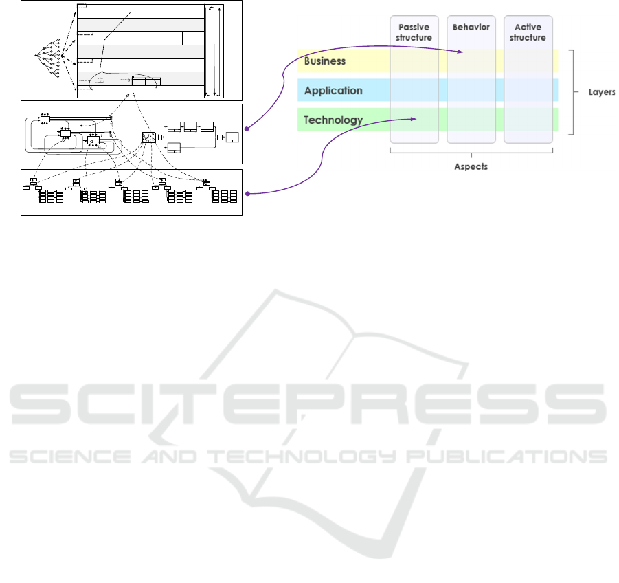
ArchiMate is also consistent with GMF.
ArchiMate is an enterprise architecture modelling
specification supporting TOGAF. It is an enterprise
architecture description language and a visual
business analysis model language. In February 2009,
the Open Group published the ArchiMate v1.0
standard as an official technical standard (The Open
Group, 2009). As shown in Fig. 6, the core layers of
ArchiMate has three layers: Technology layer,
Application layer and Business layer. The
Technology layer provides the hardware and
infrastructure services to support the Application
layer. The three layer can be related to FEAF 2.0
business layer, application layer and infrastructure
layer, which can be mapped to GAF and GMF.
ArchiMate includes three aspects, in which the
two structure aspects are related to static structure
view of GMF, and the behaviour aspect related to
behaviour view in GMF.
In June 2020, the Open Group released version 3.1
of ArchiMate (The Open Group, 2020). In addition to
core layers, the newest ArchiMate added Strategy &
EI2N 2021 - IFAC/IFIP International Workshop on Enterprise Integration, Interoperability and Networking
224
ArchiMate Core Framewor
k
GAF Modelling Framework and Views
Performance & Evaluation
Structure
Goal
Indicators
Factors
Enterprise competitive Capacity
Improvement and En terprise Success
Elements
Time Cost Qualit y Service
Environmen t Fea sibility
Software Development Cost
Putn am
Model
COCOMO
Model
L
Code Lines
td
Project duration(Year )
K
Workload of software developers and
maintenance personne l (Man/Year)
Ck is co nst an t
a,b,c and r a re constants ba sed on the project t ype.
S
is code lines (Kilo-line)
E is work load (man/per month)
D is pro ject duration (month)
Physical algorithm,
linear/nonlinear fit
Calculational methods
Weighted
Sum,geometrical
methods,vector
spac e, o ther
inte gratin g me thods
AHP, ANP,
Evaluation,Decision
Supporting Methods
Evaluating
Sturcture
System
Implemen tation
Target Deco mposition
Syste m An alysis
System Monit or and Control
Software Project Type
rC
A
B
C
3.2
3.0
2.8
1.05
1.12
1.20
System Behavior
Structures
2
3
1
2
4
1
6
5
X
X
3
Functional
Relationship
Scheduling and Logical
Relationship
System Static
Structures
Organization
Structure
Function
Structure
Resource
Structure
Information
Structure
Product/Service
Structure
Calculational methods
Calculational methods
Figure 6: GMF and ArchiMate.
Motivation layer and Implementation &Migration
layer. The Strategy & Motivation layer realizes the
modelling of stakeholders and analyses the driving
factors of innovation. This layer can help to manage
requirement, which is consistent with Performance &
Evaluation Structure of GMF.
Many other modelling methods also have certain
mapping relation with GMF.
5 CONCLUSIONS
This paper presents the general architecture
framework (GAF) and relative general modelling
framework (GMF). GAF includes following features:
The division and relationships of views: GAF
includes three layers and seven views, which
presents a new consideration to the organization of
enterprise model views.
Performance evaluation view: performance
evaluation view identifies the development and
optimization direction of SSE integration, and its
corresponding modelling and analysing methods
support enterprise re-engineering and continuous
improvement.
Model-based systems engineering (MBSE):
continuous system evolvement from the As-Is
model to the To-Be model is the key methodology
of GAF, which is an important MBSE approach for
system integration.
In the paper, mapping between GAF and other
architecture is also discussed, as well as mapping
between GMF and SSE modelling methods sets. GAF
can be used to organize model based SSE engineering
projects and GMF can be used to manage modelling
tasks and relative models.
ACKNOWLEDGEMENTS
This research is supported by the science and
technology innovation 2030 - "new generation
artificial intelligence" major project
(2018AAA0101605), the National Natural Science
Foundation of China (No.61771281, No.61174168),
the special project for industrial transformation and
upgrading of MIIT 2018 (ZB182505), and
independent research program of Tsinghua
University (2018Z05JZY015).
REFERENCES
AMICE (1993). CIMOSA: Open System Architecture for
CIM version 2.
CCSDS/ASRC (2016). Consultative committee for space
data systems.
CIOC (2001). Chief Information Officer Council. A
Practical Guide to Federal Enterprise Architecture.
Friedenthal, S., Griego, R., & Sampson, M. (2007).
INCOSE model based systems engineering (MBSE)
initiative. INCOSE 2007 symposium
Haskins, C. (2011). 4.6. 1 A historical perspective of MBSE
with a view to the future, INCOSE International
Symposium.
INCOSE. (2007). INCOSE systems engineering vision 2020.
INCOSE. (2014). INCOSE systems engineering vision 2025.
ISO JTC1 (2017). Information technology: Object
management group systems modeling language (OMG
SysML).
Mapping and Integration of Architecture and Modelling Frameworks
225

ISO JTC1 SC7 (2011). ISO 42010:2011 Systems and
software engineering: Architecture description.
ISO TC 184 SC5 (2005). ISO 15704:2000/Amd 1:2005.
Industrial automation systems - Requirements for
enterprise-reference architectures and methodologies.
ISO TC 184 SC5 (2006). ISO 19439:2006. Enterprise
integration - Framework for enterprise modelling.
ISO TC 184 SC5 (2007). ISO 19440:2007. Enterprise
integration - Constructs for enterprise modelling.
ISO TC184 SC5 (2014). ISO 22400-2:2014. Automation
systems and integration - Key performance indicators
(KPIs) for manufacturing operations management -
Part 2: Definitions and descriptions.
L. Delligatti (2013). SysML Distilled: A Brief Guide to the
Systems Modeling Language, Addison-Wesley
Professional, Illustrated Edition.
OMB (2013). The U.S. Office of Management and Budget.
Federal Enterprise Architecture Framework version 2.
Qing Li, Yuliu Chen (2007). Modelling and Analysis of
Enterprise and Information Systems - From
Requirements to Realization. Springer and High
Education Press. 2007.
P. Bernus and L. Nemes (1994). A Framework to Define a
Generic Enterprise Reference Architecture and
Methodology. Proceedings of the International
Conference on Automation, Robotics and Computer
Vision (ICARCV'94), Singapore, November 10–12,
1994.
The Open Group (2009). ArchiMate 1.0 Specification
The Open Group (2020). ArchiMate 3.1 Specification
John F. Sowa and John Zachman (1992). Extending and
Formalizing the Framework for Information Systems
Architecture. IBM Systems Journal, Vol 31, no.3, 590-
616.
EI2N 2021 - IFAC/IFIP International Workshop on Enterprise Integration, Interoperability and Networking
226
