
On-orbit Free-floating Manipulation using a Two-arm Robotic
System
Jose Luis Ramon
1a
, Jorge Pomares
1b
and Leonard Felicetti
2c
1
University of Alicante, Department of Physics, Systems Engineering and Signal Theory, Alicante, Spain
2
Cranfield University, School of Aerospace, Transport and Manufacturing, Cranfield, U.K.
Keywords: Dual-arm Manipulator, Space Robotics, On-orbit Servicing, Visual Servoing, Impedance Control.
Abstract: A direct visual-servoing algorithm is proposed for the control of a space-based two-arm manipulator. The
scenario under consideration assumes that one of the arms performs the manipulation task while the second
one has an in-hand camera to observe the target zone of manipulation. The algorithm uses both the camera
images and the force/torque measurements as inputs to calculate the control action to move the arms to
perform a manipulation task. The algorithm integrates the multibody dynamics of the robotic system in a
visual servoing framework that uses de-localized cameras. Impedance control is then used to compensate for
eventual contact reactions when the end effector touches and operates the target body. Numerical results
demonstrate the suitability of the proposed algorithm in specific tasks used in on-orbit servicing operations.
1 INTRODUCTION
Space manipulators will be used in a growing range
of missions to assemble, repair, resupply, and rescue
satellites in orbit or remove them at the end of life
(Flores-Abad et al., 2014). Rigorous requirements in
terms of accuracy and safety of the robotic operations
are generally imposed in such kinds of applications,
as it is imperative to avoid collisions that can damage
equipment or compromise the success of missions
(Felicetti et al., 2016). These tasks become even more
challenging when targets are in uncontrolled non-
cooperative conditions (Moghaddam & Chhabra,
2021) or the servicing spacecraft is maintained in a
free-floating condition (Xu et al., 2020).
In such kinds of robotic operations, the knowledge
of the relative position between the service spacecraft
and the target must be continuously monitored to
avoid collisions (Cassinis et al., 2019). Onboard
cameras are preferred over all other sensors, as they
have higher technology readiness levels, a higher
degree of reliability, and better versatility than other
solutions (Palmerini et al., 2016). Cameras can be
located on the main body of the servicing spacecraft
or on movable and reconfigurable appendages to
a
https://orcid.org/0000-0002-8635-6061
b
https://orcid.org/0000-0002-7523-9118
c
https://orcid.org/0000-0001-6830-4308
avoid occlusions of the observed scene during the
manipulation task (Peng et al., 2021; Wang et al.,
2017).
This paper focuses on the specific scenario where
a servicing spacecraft equipped with robotic arms
performs on-orbit servicing and manipulation
operations. Specifically, the spacecraft is assumed to
be equipped with two robotic arms serving the
manipulation and observation functions, respectively.
The first manipulator is an anthropomorphic robotic
arm with all the useful tools to grasp and manipulate
parts of the target satellite. The second manipulator is
a robotic arm with an eye-in-hand camera system
used to observe the specific target area where the
robotic operations are performed. In addition, in order
to better perform the manipulator task, it is necessary
to have also knowledge of the contact forces and
torques with the targets. For this reason, the scenario
assumes that force sensors at the end-effector are able
to measure these actions (Garcia et al., 2019).
This paper proposes a new approach to build a
visual servoing controller that considers the relative
free-floating condition of the bodies involved in the
operations and integrates it with an impedance control
strategy for compensating eventual contact reactions
Ramon, J., Pomares, J. and Felicetti, L.
On-orbit Free-floating Manipulation using a Two-arm Robotic System.
DOI: 10.5220/0010712100003061
In Proceedings of the 2nd International Conference on Robotics, Computer Vision and Intelligent Systems (ROBOVIS 2021), pages 57-63
ISBN: 978-989-758-537-1
Copyright
c
2021 by SCITEPRESS – Science and Technology Publications, Lda. All rights reserved
57
during the manipulation. Visual servoing is a well-
known approach to guide robots using visual
information obtained from cameras (Chaumette &
Hutchinson, 2006). Image-based visual servoing
systems allow for the robot guidance by only using
image information and do not require reconstructing
the 3D position of the target to guide the robot. The
proposed controller assumes that the target trajectory
is defined directly in the image space, and it
calculates the torques to be applied to the
manipulator's joints to perform the manipulation task.
The proposed direct image-based visual servoing
control outputs the joint torques directly, without
having internal control loops of servo motors. This
characteristic offers advantages in the guidance of
space robots: eventual actions on the main servicing
spacecraft body can be easily computed and
predicted. In (Alepuz et al., 2016), a direct image-
based controller is proposed for the guidance of a
free-floating manipulator using an eye-in-hand
camera. In (Pomares et al., 2018), a visual servoing
system is proposed to guide a spacecraft during a
rendezvous manoeuvre. In this case, a camera is
attached to the servicing spacecraft. The approach
presented in this paper assumes that the camera is
moving alongside the second arm. Consequently,
control actions are generated independently of the
unknown position of the camera. The second arm can
be moved to ensure better views of the observed scene
of manipulation.
The proposed visual servoing algorithm also
integrates force and torque measurements at the
manipulator end effector to increase the system
robustness when interacting with the target body. A
mix between a visual servoing controller and
impedance control is proposed in (Garcia et al., 2020)
to perform spacecraft docking in on-orbit servicing
operations. Impedance control is also used in (Mitros
et al., 2017) to evaluate and compensate the interface
contact actions during on-orbit docking manoeuvres
between two spacecraft. A servicing spacecraft with
a force-controlled manipulation system is also
presented in (Dalyaev et al., 2018), using an
impedance control to touch and move the end effector
over the target surface. In on-orbit servicing
applications, the relative dynamics and eventual
contact dynamics between the target and the servicing
spacecraft might strongly affect the performance of
the robotic operations. In such circumstances, indirect
approaches are preferable over direct ones. This is the
case of the algorithms proposed in (Garcia et al.,
2019) (Garcia et al., 2020), where the impedance
controller is paired with a vision control to help keep
the manipulator aligned during the manipulation
tasks. The algorithm presented in this paper proposes
an image-based visual impedance control law that
simultaneously combines the inputs from the camera
and the force sensors. Simulation results will show
that the use of such a controller allows for an increase
of tracking precision with respect to the previous
direct visual servoing approaches. To validate the
methodology, this paper shows the results of an
insertion task. The proposed controllers can
compensate for the tool's eventual misalignments
while this is inserted in a hole in the target spacecraft.
The remaining part of the paper is organized as
follows: Section 2 describes the system architecture
proposed for the servicing spacecraft and its
dynamics. The visual servoing and interaction control
are described in Section 3 and Section 4, respectively.
Section 5 presents the numerical results used to assess
the controllers' validity and robustness on the
trajectory tracking and the tool insertion tasks.
Finally, Section 6 summarizes the main findings and
presents the concluding remarks.
2 SYSTEM ARCHITECTURE
2.1 On-orbit Servicing Scenario
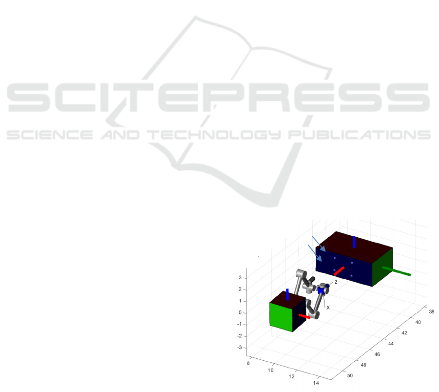
A representation of the on-orbit servicing scenario is
shown in Figure 1. A servicing spacecraft is supposed
to perform some on-orbit servicing operations to a
target spacecraft. The servicing spacecraft is equipped
with two robotics arms that serve two functions:
manipulation and observation, respectively. The first
manipulator has 𝑛𝑒 rotational joints and it is used for
accomplishing the manipulation tasks. The second
manipulator is a robotic arm with 𝑛𝑐 degrees of
freedom with an eye-in-hand camera system.
Figure 1: On-orbit servicing scenario.
X(m)
Y(m)
Z(m)
B
T
Base
Spacecraf
t
Robotic
camera
Manipulato
r
Targe
t
Spacecraf
t
Target
features
C
E
ROBOVIS 2021 - 2nd International Conference on Robotics, Computer Vision and Intelligent Systems
58

A pattern with 𝑚 points is attached to the target
spacecraft. The robotic camera will use this to
identify the relative pose of the target spacecraft.
Figure 1 also shows the coordinate frames
adopted in this study. The B frame is attached to the
servicing spacecraft's main body, and the T frame is
used for the target spacecraft. Two other coordinate
frames represent the pose of the end-effectors of both
the robotic arms: the C frame at the eye-in-hand
camera and the E frame at the end of the manipulator's
arm. Finally, an Earth Centered Inertial coordinate
frame, called I, is adopted as a reference frame for
calculating the objects' positions and attitudes
included in the scenario.
2.2 System Dynamics
The current configuration of the servicing spacecraft
and its two robotic arms is represented by the state
vector 𝝐𝒕
,𝝓
,𝒒
,𝒒
, where 𝒕
and 𝝓
are
the position vector and attitude coordinates (Euler
angles) of the base spacecraft with respect to the
Inertial frame and, 𝒒
and 𝒒
are the joint angles of
both the manipulator and the robotic camera,
respectively.
The equation of motion of robotic system can be
written as (Pisculli et al., 2014):
𝒉
𝝉
𝝉
=
𝑴
𝑴
𝑴
𝑴
𝑴
0
𝑴
0𝑴
𝒗
𝒒
𝒒
+
𝒄
𝒄
𝒄
𝑱
𝟎
𝒉
𝟎
(1)
where 𝒒
and 𝒒
is the set of joint accelerations of the
robot manipulator and camera, respectively, 𝒗
𝒕
,𝝎
∈ ℜ
6
denotes the linear and angular
accelerations of the base spacecraft expressed in the
Inertial coordinate frame, 𝑴
∈ ℜ
6×6
is the inertia
matrix of the base spacecraft, 𝑴
∈ ℜ
6×ne
is the
coupling matrix between the spacecraft and the
manipulator, 𝑴
∈ ℜ
ne×ne
is the inertia matrix of the
manipulator, 𝑴
∈ ℜ
6×nc
is the coupling matrix
between the spacecraft and the robotic camera,
𝑴
∈ ℜ
nc×nc
is the inertia matrix of the robotic
camera; 𝒄
, 𝒄
, and 𝒄
∈ ℜ
6
are a
velocity/displacement-dependent, non-linear terms
for the base, manipulator and robotic camera,
respectively, 𝒉
∈ ℜ
6
includes both the force and
torque exerted on the base of the servicing spacecraft
but in this paper no forces and torques will be applied
to the servicing spacecraft, 𝝉
∈ ℜ
ne
and 𝝉
∈ ℜ
nc
are the applied set of joint torques acting on the robot
manipulator and on the robotic camera, respectively.
It is also worth noting that eventual external wrenches
𝒉
on the end effector can be projected into the joint
space by using the Jacobian 𝑱
and therefore can be
included into the robot dynamics.
3 VISUAL SERVOING
The proposed visual-based control uses features of
the target body for driving both the robotic
manipulator and the robotic camera. Figure 1 shows
a pattern of 𝑚 points attached on the body of the
target satellite that might represent possible visual
features observed by the robotic camera. These points
have fixed positions with respect to the target
coordinate frame (𝒑
,
𝑥
,
𝑦
,
𝑧
,
, with 𝑖
1…𝑚), but they will appear as 2D points in the
camera image plane 𝒔
,
𝑋
,
,𝑌
,
∈ℜ
, after
being projected through a pin-hole camera model (Ma
et al., 2015). The controller is built upon the concept
that the same set of 𝑚 features seen in the target can
be virtually generated and attached to the
manipulator's end effector and therefore moving
rigidly with it.
The visual-servoing controller aims to match the
virtual features with ones attached to the target. In this
way, the robotic manipulator follows a specified
trajectory defined in the image plane of the robotic
camera. Thus, the position of each of the virtual
features, 𝒑
,
, with 𝑖1…𝑚, will be considered
constant with respect to the coordinate frame of the
end-effector. The corresponding virtual image
features, 𝒔
,
𝑋
,
,𝑌
,
∈ℜ
, are obtained taking
into account the manipulator kinematics. The camera
position is known from the actual arm configuration;
therefore, it is possible to relate the manipulator end-
effector position with the position of the robotic
camera through an algebraic relation given by the
direct kinematics of the two manipulators. A pin-hole
camera model is then used for projecting each of the
points in the camera frame 𝒑
,
𝑥
,
,𝑦
,
,𝑧
,
onto the image plane, 𝒔
,
𝑋
,
,𝑌
,
, using the
following equation:
𝒔
,
1
𝑧
,
𝑥
,
𝑦
,
(2)
where 𝒑
,
𝑥
,
,𝑦
,
,𝑧
,
∈ℜ
is the position of
the i-th point with respect the camera frame. The time
derivative of the virtual features are:
𝒔
,
𝑋
,
,𝑌
,
𝑳
,
𝒑
,
(3)
On-orbit Free-floating Manipulation using a Two-arm Robotic System
59

with:
𝑳
,
1
𝑧
,
10𝑋
,
01𝑌
,
(4)
The value of 𝒑
,
can be obtained from 𝒑
,
taking
into account the relationship between both frames:
𝒑
,
𝑬
𝑠𝑘𝑹
𝒑
,
𝑹
𝟎
𝟎
𝑹
∙
∙
𝒗
𝒗
(5)
where 𝑹
is the rotation matrix between the camera
and the Inertial frame, 𝒗
and 𝒗
are the twist of the
end-effector, E, and the camera, C, with respect the
Inertial frame, and 𝑬
∈ℜ
the identity matrix.
Finally, the Jacobian matrix 𝑱
,
can be defined as:
𝒔
,
𝑳
,
𝑬
𝑠𝑘𝑹
𝒑
,
𝑹
𝟎
𝟎
𝑹
𝒗
𝒗
𝑱
,
𝒗
𝒗
(6)
On the other hand, the time derivative of the visual
features extracted from the target spacecraft (using
the robotic camera) can be obtained using the
interaction matrix, 𝑳
,
, used in classical image-based
visual servoing systems ( Ma et al., 2015):
𝑳
,
⎣
⎢
⎢
⎢
⎡
1
𝑧
,
0
𝑋
,
𝑧
,
0
1
𝑧
,
𝑌
,
𝑧
,
𝑋
,
𝑌
,
1 𝑋
,
𝑌
,
1 𝑌
,
𝑋
,
𝑌
,
𝑋
,
(7)
Therefore:
𝒔
,
𝑋
,
,𝑌
,
𝑳
,
𝑹
𝟎
𝟎
𝑹
𝒗
𝑱
,
𝒗
(8)
The aim of the visual-servoing controller is to reduce
the image error 𝒆
𝒔
𝒔
to zero, where 𝒔
𝒔
,𝒔
,…,𝒔
and 𝒔
𝒔
,𝒔
,…,𝒔
are
the virtual features and the real ones extracted by the
robotic camera, respectively.
4 INTERACTION CONTROL
The proposed control scheme takes the contact
dynamics between the two bodies into account to
compensate for eventual reactions and disturbances
produced during the contact. This study assumes that
the target spacecraft has a greater mass than the
servicing spacecraft so that the target's motion does
not change significantly due to the interaction with
the servicer's end-effector. On the other hand,
reaction forces produced by the contact dynamics can
produce significant changes in both the position and
attitude dynamics of the servicing spacecraft.
A damper-spring model is used in this paper to
characterize this kind of interaction. Therefore, the
visual servoing approach generates a virtual damper-
spring behaviour for the pose displacement generated
by the visual error (Tommasino et al., 2020)
:
𝑫𝒗
𝜶𝒉
(9)
where 𝑫 is the damping matrix, 𝒗
is the desired
twist of the manipulator-end and includes both linear
and angular velocities, 𝒉
∈ℜ
is the external
wrench action on the manipulator and 𝜶∈ℜ
is the
control law to be defined for the visual servoing task.
The following Lyapunov function is considered:
𝑽
𝒆
1
2
𝒆
𝑸𝒆
(10)
where 𝑸 is a diagonal positive definite matrix to
guarantee the system stability. The time derivative of
the previous Lyapunov function is:
𝑽
𝒆
𝒆
𝑸𝒆
(11)
By using Eq. (6) and (8), the time derivative of the
image error can be calculated as:
𝒆
𝒔
𝒔
𝑱
𝒗
𝒗
𝑱
𝒗
𝑱
𝒗
𝑱
𝑱
𝒗
𝑱
𝒗
𝑱
𝒗
(12)
where 𝑱
𝑱
,
,𝑱
,
,…,𝑱
,
∈ℜ
, 𝑱
𝑱
,
,𝑱
,
,…,𝑱
,
∈ℜ
and 𝑱
𝑱
𝑱
.
Thus, by taking into account Eq.(12) and (9), the
value of 𝑽
becomes:
𝑽
𝒆
𝒆
𝑸
𝑱
𝒗
𝑱
𝒗
𝒆
𝑸
𝑱
𝑫
𝒉
𝜶
𝑱
𝒗
(13)
and, if we consider the following control action:
𝜶𝑫
𝑲
𝑱
𝑸𝒆
𝑱
𝑱
𝒗
(14)
being 𝑲 a positive definite matrix, Eq. (13) becomes:
𝑽
𝒆
𝒆
𝑸
𝑱
𝑫
𝒉
𝒆
𝑸
𝑱
𝑲
𝑱
𝑸𝒆
(15)
It is worth noting that, when the robot does not
interact with the target spacecraft, there are no
external actions acting on the end-effector (𝒉
0),
therefore 𝑽
𝒆
𝒆
𝑸𝑱
𝑲𝑱
𝑸𝒆
and
consequently, the system in Eq.(9) is asymptotically
ROBOVIS 2021 - 2nd International Conference on Robotics, Computer Vision and Intelligent Systems
60
stable: the reference trajectory tracking task will be
achieved at the equilibrium 𝒆
0 if 𝑱
is
nonsingular. On the other hand, when the robot
interacts with the target spacecraft, Eq. (9) can be
used in conjunction with Eq.(14) to obtain:
𝑫𝒗
𝑫𝑲
𝑱
𝑸𝒆
𝑲
𝑱
𝑱
𝒗
𝒉
(16)
The desired interaction compliance can be defined in
the Cartesian space by means of the matrices 𝑲 and
𝑫 and the image convergence can be regulated by
setting selected gains for 𝑸. Specifically, this is done
by formulating an optimal control strategy for
tracking the reference trajectory obtained from the
interaction wrench and the image error. This tracker
has been developed in (Pomares et al., 2015).
5 RESULTS
Simulations have been carried on to assess the
performance of the proposed visual-servoing control
strategy when performing the task of tool insertion
into the body of the target spacecraft. A predefined
trajectory is followed by the robotic camera. This
trajectory is pre-planned offline so that the visual
features remain within the field of view during the
task. The control of the robot camera trajectory is out
of the scope of this study, but approaches like the ones
shown in (Garcia et al., 2020) (Mitros et al., 2017) can
guarantee that the camera can correctly observe the
areas of interest for performing the operations.
The mass properties of the manipulator, of the
robotic camera and of the base satellite are listed in
Table 1. The controller matrices are set as follows:
𝑸𝑑𝑖𝑎𝑔
0.01
∈ ℜ
2m2m
,
𝑲 = 𝑑𝑖𝑎𝑔0.1,0.1,0.4,10,10,15,
𝑫𝑑𝑖𝑎𝑔100,100,400,10,10,20,
where 𝑑𝑖𝑎𝑔 is a matrix
with the diagonal elements
equal to the argument of the function. The camera
acquires 20 images per second with a resolution of
640x480 pixels but the control loop is running at 5
ms. The camera is supposed to be previously
calibrated and the intrinsic parameters are (u
0
, v
0
) =
(298, 225) px, and (f
u
, f
v
) = (1082.3, 1073.7) px,
where u
0
and v
0
are the position of the optical center
and f
u
and f
v
are the focal lengths in the x and y
directions, respectively. A tool is held by the robotic
manipulator end-effector and needs to inserted 2 cm
into the target spacecraft.
An offset of 3 mm from the ideal configuration of
the virtual features is included in the desired pattern
to simulate an error in the final pose. In this way, it is
possible to evaluate the effectiveness of the proposed
control scheme to guide the robotic manipulator in the
presence of contact forces: some adjustments will be
needed by the embedded impedance control.
Table 1: Dynamic parameters of the robot.
Base
Mass
(Kg)
Inertia (kg∙m
2
)
I
x
I
y
I
z
2550 6200 3540 7090
Arms
Mass
(Kg)
Inertia (kg∙m
2
)
I
x
I
y
I
z
2550 6200 3540 7090
Link1
35 2 0.2 2
Link2
22 3 0.2 3
Link3
22 3 0.2 3
Link4
10 0.15 0.2 0.4
Link5
10 0.15 0.2 0.3
Link6
10 0.2 0.25 0.3
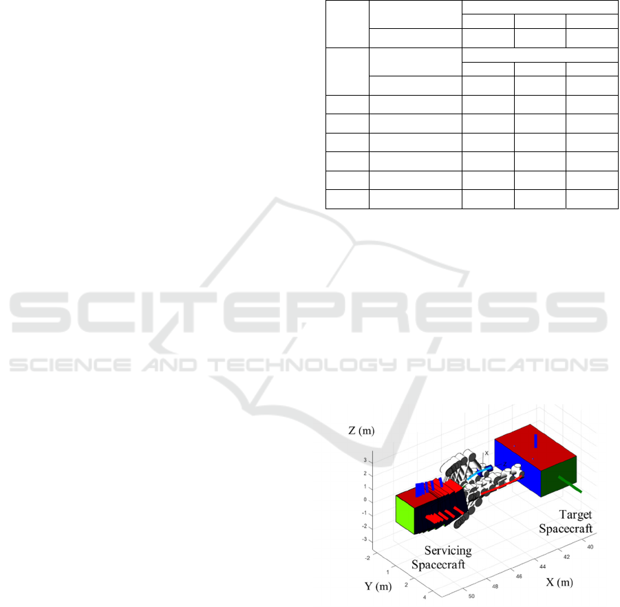
The simulation results are shown from Figure 2 to
Figure 4. Specifically, the 3D trajectory described by
the robotic system is shown in Figure 2, where the
trajectory of the manipulator is highligthed in red and
the trajectory of the robotic camera in blue. From the
overlapping frames, it is possible to evaluate the
movements of the manipulator, which tries to extend
its arm to reach the target. At the same time, the
floating base of the satellite moves backwards as a
reaction to the motion of both manipulator and
robotic camera.
Figure 2: Robot arm trajcetories during the tool insertion
task.
The corresponding motion of the image features
in the image plane is shown in Figure 3. The
trajectories of the visual features extracted from the
target spacecraft are represented in blue, and the
trajectories of the virtual features are shown in red.
On-orbit Free-floating Manipulation using a Two-arm Robotic System
61
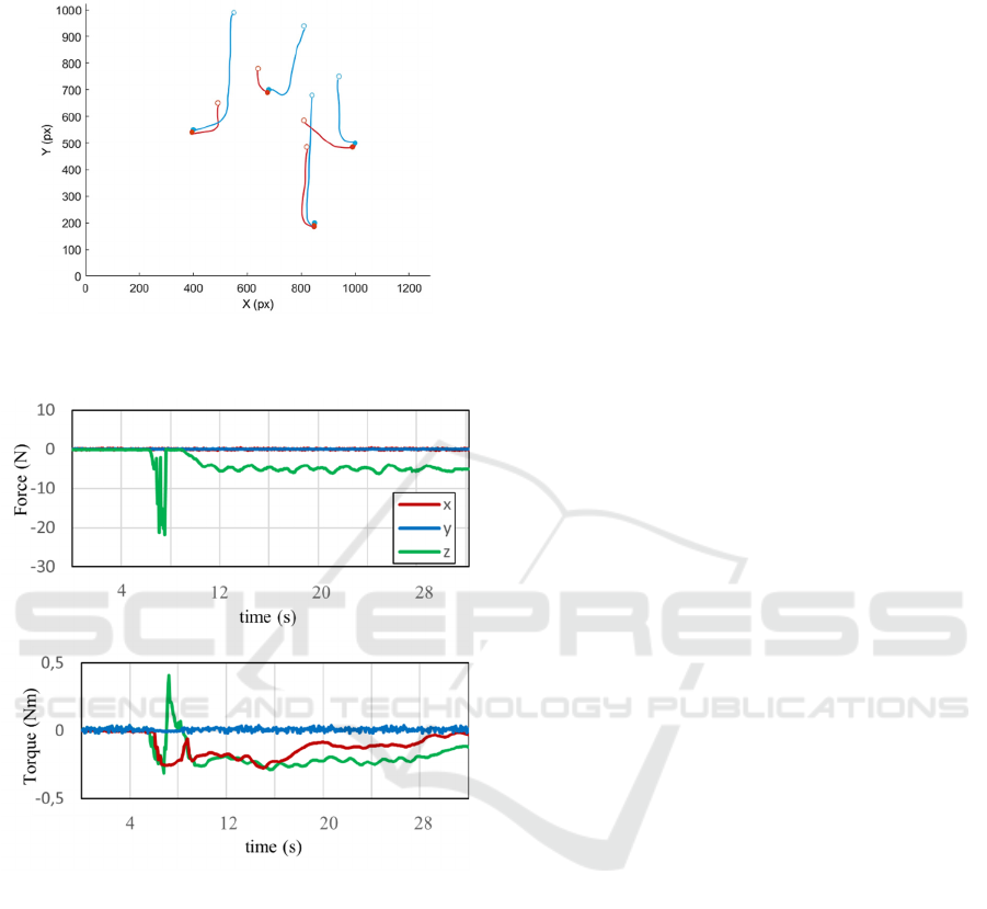
Empty circles and the final features indicate the initial
features are shown by solid circles.
Figure 3: Image trajectories of the virtual and real visual
features.
Figure 4: Reaction forces and torques during the insertion
task.
As expected, the positions of the extracted image
features and virtual features are initially very far from
each other, but they tend to approach each other
during the manoeuvre. However, their final position
in the image plane is not perfectly matching due to the
offset between the actual virtual target configuration
and the ideal one. The controller, in any case,
compensates for this error by using the impedance
strategy shown in Section 4. The time behaviour of
the reaction forces and torques at the end effector of
the manipulator are shown in Figure 4. The peak of
the contact forces is reached after 7 s, when the tool
touches the target for the first time but cannot be
correctly inserted in the first attempt. After this initial
phase, the offset on the virtual target image is
compensated within the controller. The contact forces
reduce their values when the tool is centred and
inserted into the hole.
6 CONCLUSIONS
The paper presented a direct visual servoing
algorithm suitable for on-orbit servicing and
manipulation. The algorithm is applicable to a
spacecraft equipped with two-arm manipulator. The
two arms are dedicated to manipulation and
observation tasks, respectively.
A visual servoing controller independent from the
observed scene's point of view was consequently
developed. The virtual features could be virtually
reconstructed following a specific pattern seen on the
target body and consequently assumed attached to the
end effector of the operating manipulator.
The controller was able to drive the manipulator
in such a way to make the virtual features match the
real features on the target body. Under an impedance
control scheme, the controller also compensated for
eventual contact reactions between the end effector
and the target satellite. Simulations demonstrated the
applicability of this scheme in a standard multi-
degrees of freedom manipulator scenario where
eventual misalignments that would not allow for a
tool insertion task inside the body of the target
satellite were compensated and corrected by the
controller, making this kind of operation still
successful.
Further studies will assess the robustness of the
proposed controller against environmental torques
and forces as well as will evaluate the performance of
the controller with different frame rates of the camera,
and will compare the results with other tracking
controllers.
REFERENCES
Alepuz, J. P., Emami, M. R., & Pomares, J. (2016). Direct
image-based visual servoing of free-floating space
manipulators. Aerospace Science and Technology, 55,
1–9. https://doi.org/10.1016/j.ast.2016.05.012.
Cassinis, L. P., Fonod, R., & Gill, E. (2019). Review of the
robustness and applicability of monocular pose
estimation systems for relative navigation with an
uncooperative spacecraft. Progress in Aerospace
Sciences, 110, 008.
Chaumette, F., & Hutchinson, S. (2006). Visual servo
control. I. Basic approaches. IEEE Robotics &
ROBOVIS 2021 - 2nd International Conference on Robotics, Computer Vision and Intelligent Systems
62

Automation Magazine, 13(4), 82–90. https://doi.org/
10.1109/MRA.2006.250573.
Dalyaev, I., Titov, V., & Shardyko, I. (2018). A concept of
robotic system with force-controlled manipulators for
on-orbit servicing spacecraft. En Proceedings of the
Scientific-Practical Conference «Research and
Development - 2016» (pp. 239-245). Springer
International Publishing.
Felicetti, L., Gasbarri, P., Pisculli, A., Sabatini, M., &
Palmerini, G. B. (2016). Design of robotic manipulators
for orbit removal of spent launchers' stages. Acta
Astronautica, 119, 118–130. https://doi.org/10.1016/
j.actaastro.2015.11.012.
Flores-Abad, A., Ma, O., Pham, K., & Ulrich, S. (2014). A
review of space robotics technologies for on-orbit
servicing. Progress in Aerospace Sciences, 68, 1–26.
https://doi.org/10.1016/j.paerosci.2014.03.002.
Garcia, J., Gonzalez, D., Rodriguez, A., Santamaria, B.,
Estremera, J., & Armendia, M. (2019). Application of
Impedance Control in Robotic Manipulators for
Spacecraft On-orbit Servicing. 2019 24th IEEE
International Conference on Emerging Technologies
and Factory Automation (ETFA), 836–842.
https://doi.org/10.1109/ETFA.2019.8869069.
Garcia, J., Rodriguez, A., Estremera, J., Santamaria, B.,
Gonzalez, D., & Armendia, M. (2020). Visual Servoing
and Impedance Control in Robotic Manipulators for
On-Orbit Servicing. 2020 25th IEEE International
Conference on Emerging Technologies and Factory
Automation (ETFA), 1, 734–741. https://doi.org/
10.1109/ETFA46521.2020.9211989.
Ma, G., Jiang, Z., Li, H., Gao, J., Yu, Z., Chen, X., Liu, Y.-
H., & Huang, Q. (2015). Hand-eye servo and
impedance control for manipulator arm to capture target
satellite safely. Robotica, 33(4), 848–864.
https://doi.org/10.1017/S0263574714000587.
Mitros, Z., Rekleitis, G., & Papadopoulos, E. (2017).
Impedance control design for on-orbit docking using an
analytical and experimental approach".
Moghaddam, B. M., & Chhabra, R. (2021). On the
guidance, navigation and control of in-orbit space
robotic missions: A survey and prospective vision. Acta
Astronautica, 184, 70–100. https://doi.org/10.1016/
j.actaastro.2021.03.029.
Nocerino, A., Opromolla, R., Fasano, G., & Grassi, M.
(2021). LIDAR-based multi-step approach for relative
state and inertia parameters determination of an
uncooperative target. Acta Astronautica, 181, 662–678.
https://doi.org/10.1016/j.actaastro.2021.02.019.
Palmerini, G. B. (2016). Relative navigation in autonomous
spacecraft formations. 2016 IEEE Aerospace
Conference, 1–10. https://doi.org/10.1109/AERO.20
16.7500944.
Peng, J., Xu, W., Liu, T., Yuan, H., & Liang, B. (2021).
End-effector pose and arm-shape synchronous planning
methods of a hyper-redundant manipulator for
spacecraft repairing. Mechanism and Machine Theory,
155, 104062–. https://doi.org/10.1016/j.mechmach
theory.2020.104062.
Pisculli, A., Felicetti, L., Gasbarri, P., Palmerini, G. ., &
Sabatini, M. (2014). A reaction-null/Jacobian transpose
control strategy with gravity gradient compensation for
on-orbit space manipulators. Aerospace Science and
Technology, 38, 30–40. https://doi.org/10.1016/j.ast.20
14.07.012.
Pomares, J., Felicetti, L., Pérez, J., & Emami, M. R. (2018).
Concurrent image-based visual servoing with adaptive
zooming for non-cooperative rendezvous maneuvers.
Advances in Space Research, 61(3), 862–878.
https://doi.org/10.1016/j.asr.2017.10.054.
Pomares, J., Jara, C. A., Pérez, J., & Torres, F. (2015).
Direct visual servoing framework based on optimal
control for redundant joint structures. International
Journal of Precision Engineering and Manufacturing,
16(2), 267–274. https://doi.org/10.1007/s12541-015-
0035-z.
Tommasino D., Cipriani G., Doria A., Rosati G. (2020)
Effect of End-Effector Compliance on Collisions in
Robotic Teleoperation. Applied Sciences. 10(24), 9077.
https://doi.org/10.3390/app10249077.
Wang, H., Guo, D., Xu, H., Chen, W., Liu, T., & Leang, K.
K. (2017). Eye-in-hand tracking control of a free-
floating space manipulator. IEEE transactions on
aerospace and electronic systems, 53(4), 1855-1865.
Xu, R., Luo, J., & Wang, M. (2020). Kinematic and
dynamic manipulability analysis for free-floating space
robots with closed chain constraints. Robotics and
Autonomous Systems, 130, 103548–. https://doi.org/
10.1016/j.robot.2020.103548.
On-orbit Free-floating Manipulation using a Two-arm Robotic System
63
