
An Unmanned Aerial Carrier and Anchoring Mechanism for
Transporting Companion UAVs
Yiyong Gou
a
, Lucas Dahl
b
, Jan Kr
¨
uger
c
, Cavid Karca
d
, Dean Boonen
e
and Rico M
¨
ockel
f
DKE SwarmLab, Department of Data Science and Knowledge Engineering,
Maastricht University, Maastricht, The Netherlands
Keywords:
Unmanned Aerial Carrier, Anchor Design, Companion UAV, Aerial Anchoring Mechanism.
Abstract:
This paper demonstrates an unmanned aerial carrier as well as a new anchoring mechanism for connecting
and transporting companion unmanned aerial vehicles (UAVs). Establishing this platform presents unique
challenges including the requirements of precise localization of the platform, real-time environment mapping
system, robust flight control approach, docking safety mechanism, and reliable anchor system for the compan-
ion UAV. To obtain the positioning information, a tightly-coupled visual-inertial optimization based odometry
is implemented with a fisheye camera and an inertial measurement unit. A 3D map is updated in real-time
using an Octomap framework. A nonlinear position model predictive controller cascaded with a DJI attitude
controller is implemented for the flight control. Innovatively, we designed a lightweight anchoring mechanism
for safe landing and reliable transportation of the companion UAV. Real-world experiments results suggest
that the transportation system is a viable approach to transport the companion UAV, and that the proposed
anchoring mechanism allows for reliable operation.
1 INTRODUCTION
Recent years have witnessed the development and ex-
ploration of a variety of multi-robot systems. In these
distributed systems, robots cooperate to achieve tasks
that an individual robot would not be capable of. Of-
ten the strengths of robots with different configura-
tions and abilities are combined. Demonstrated exam-
ples of multi-robot systems include multi-drone par-
cel delivery (Peng et al., 2019), self-reconfigurable
perception-driven modular robots (Daudelin et al.,
2018), and the combination of unmanned aerial vehi-
cles (UAVs) and unmanned ground vehicles (Yu et al.,
2018; Ullah et al., 2021).
This work contributes the design and exploration
of a new light-weight anchoring mechanism for aerial
carrier UAVs. In addition, an aerial carrier is pre-
sented that, with the help of the proposed anchoring
mechanism, can carry a small companion UAV. The
a
https://orcid.org/0000-0001-7544-4675
b
https://orcid.org/0000-0002-6536-2243
c
https://orcid.org/0000-0002-7589-7604
d
https://orcid.org/0000-0002-8270-7418
e
https://orcid.org/0000-0001-8096-1829
f
https://orcid.org/0000-0001-5497-3754
combination of both UAVs is advantageous for human
operators that e.g., desire to perform aerial inspec-
tions: The aerial carrier provides to the companion
UAV long-distance travel, communication, and con-
trol as well as the necessary computational resources
for automatic image processing. In return, the com-
panion UAV allows reaching small areas that the car-
rier cannot get into. The more expensive companion
UAV can also be chosen to undergo inspection oper-
ations that might lead to a loss of the UAV and thus
are too risky to be handled by the higher-costs carrier
UAV.
1.1 Related Work
In general, aerial robotic transportation platforms re-
quire a reliable onboard flight system which typically
consists of precise localization, environment percep-
tion and flight control modules (Lutz et al., 2020).
Aerial robotic localization has been investigated us-
ing computer vision (Qin et al., 2018; Bloesch et al.,
2017), global navigation satellite system (Loianno
et al., 2018), inertial measurements (Afrisal et al.,
2019), laser (Zhang and Singh, 2014), and Ultra
Wide Band (Perez-Grau et al., 2017) based meth-
ods, among which the multi-sensors fusion approach
Gou, Y., Dahl, L., Krüger, J., Karca, C., Boonen, D. and Möckel, R.
An Unmanned Aerial Carrier and Anchoring Mechanism for Transporting Companion UAVs.
DOI: 10.5220/0010655500003061
In Proceedings of the 2nd International Conference on Robotics, Computer Vision and Intelligent Systems (ROBOVIS 2021), pages 103-112
ISBN: 978-989-758-537-1
Copyright
c
2021 by SCITEPRESS – Science and Technology Publications, Lda. All rights reserved
103
is often utilized to obtain higher localization pre-
cision. Mostly lightweight lidar and stereo cam-
eras are selected to provide 3D information for en-
vironment perception (Hornung et al., 2013; Lin
et al., 2019). Cascade control techniques with
two level controllers are generally implemented in
flight control application and onboard position con-
troller such as proportional-integral-derivative con-
trol, gain-scheduled proportional-integral-derivative
control(Wasim et al., 2019), model predictive con-
trol (MPC) (Kamel et al., 2017; Kamel et al., 2016;
Tzoumanikas et al., 2019), and geometric control
(Lee et al., 2010) are adopted and normally followed
by an off-the-shelf autopilot as the inner loop attitude
controller.
With respect to the UAV docking platform, an
aerial recharging docking platform was developed
and implemented in (Jain and Mueller, 2020; Jain
et al., 2020) and they are both tested to achieve ac-
curate docking with the localization information pro-
vided by an indoor position tracking system. As-
sisted with artificial vision, a ground landing mech-
anism with four bowl-shape inner cones surfaces was
developed for the UAV docking and recharging (Coc-
chioni et al., 2014), but it was designed for ground
static landing and cannot ensure safety in case of
the carrier wobbling that might cause the compan-
ion UAV dropping. Moreover, a UAV docking plat-
form with the ground mobile manipulator attached
with an eye-in-hand visual sensor was built and im-
plemented with UAV (Narv
´
aez et al., 2017; Narv
´
aez
et al., 2020). A special in-flight docking platform with
a customized vertical mast as a docking mechanism
mounted above on the aerial carrier was simulated
with a quadcopter assisted by the Global Positioning
System (GPS) and a computer vision process (Rocha
and Robinson, 2020). In current research, the dock-
ing platforms are mostly operating on the ground or
lack of the ability of environment perception, or rely
on an external positioning system. Additionally, these
platform are not equipped with robust fault-tolerance
mechanisms which ensure reliable and safe docking.
1.2 Contributions
The contributions of this paper include the following:
1. A novel design and validation of a lightweight an-
chor system which is customized for docking and
transporting companion UAVs.
2. Development and design of hardware and soft-
ware of a custom-made aerial carrier with
mounted anchoring mechanism.
2 PLATFORM HARDWARE
DESIGN
Given the requirement of achieving aerial transport
and anchoring for the companion UAV, the consid-
erations concerning the platform hardware design in-
clude the structural stability, available payload, struc-
tural protection, and fault-tolerance of the anchoring
mechanism and aerial carrier. In this section, we
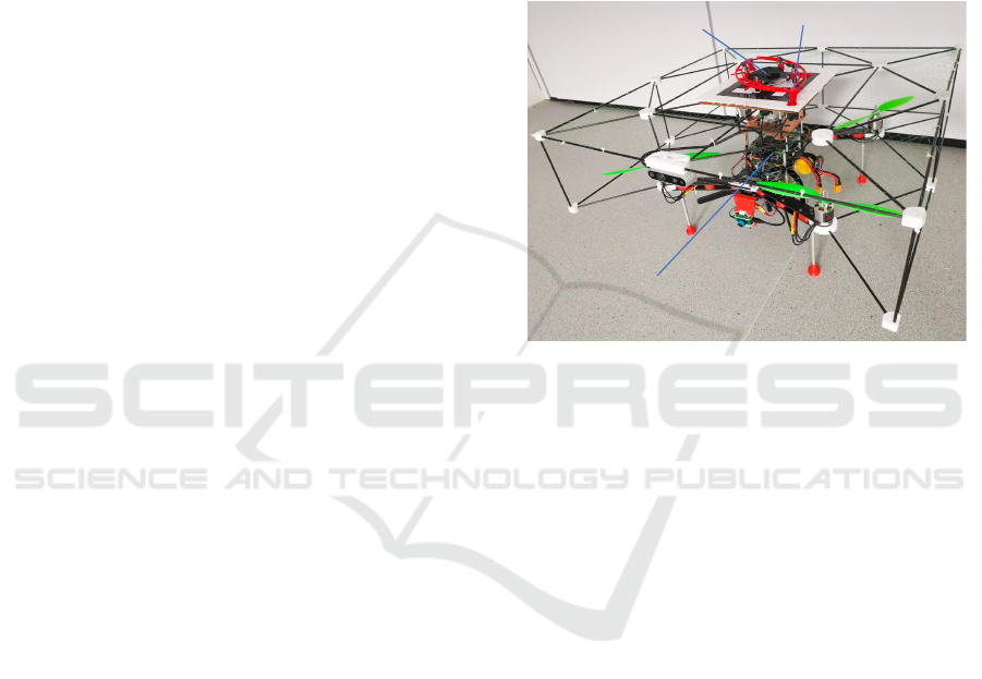
present the system hardware as shown in Figure 1.
Companion UAV
Anchoring mechanism
Aerial carrier
Figure 1: Aerial carrier with anchoring mechanism and at-
tached companion UAV.
2.1 Hardware Overview
The whole system hardware consists of four major
elements: (1) an aerial carrier with onboard com-
putational resources running software for perception
and control, (2) an anchor mechanism integrated onto
the aerial carrier for anchoring a companion UAV,
(3) a modified DJI Tello companion UAV with a
changed downward camera, and (4) a ground station
for monitoring and communication with the aerial
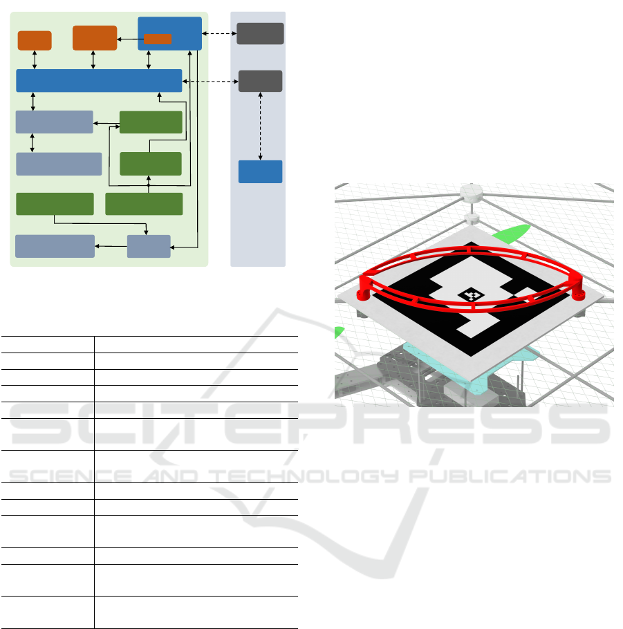
platforms. Figure 2 shows a block diagram of the
electronics hardware components of the carrier UAV
and ground station. Table 1 provides additional speci-
fications. With a total system weight (including aerial
carrier 3.918kg, companion UAV 0.086kg, and an-
choring mechanism 0.146kg) of 4.15kg, the carrier
UAV reaches a flight time of up to eight minutes in
operation mode.
2.2 Design of Anchoring Mechanism
and Protection
The anchoring mechanism shown in Figure 3 is com-
posed of a 3mm-thick foam board featuring a frac-
tal marker (Romero-Ramirez et al., 2018; Romero-
Ramire et al., 2019; Garrido-Jurado et al., 2016) for
ROBOVIS 2021 - 2nd International Conference on Robotics, Computer Vision and Intelligent Systems
104
D435i
Fisheye
Camera
IMU
DJI N3 Autopilot
Intel NUC i7
Brushless Motor x 4
U2D2 & Power Hub
DYNAMIXEL-XL330 x 2
& Anchor
Battery 4S 2200mAh
Battery 4S 6200mAh
UBEC 5V
UBEC 12V
PWM
USB 3 USB 2
WIFI
Router
ThinkPad
T470S
UART
5V DC
TTL
ESC x 4
PWM
USB 2
DC 4S
12V DC
DC 4S
Three Phase AC
WIFI
WIFI
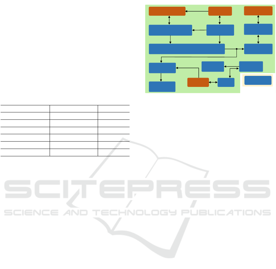
Aerial Carrier
Ground Station
Radiolink
AT9S RC
Radio
Figure 2: Ground station and electronic hardware compo-
nents of aerial carrier.
Table 1: System components and specifications.
Components Specifications
DC motor * 4 Turnigy 3542-800kv
Propeller * 4 4.7inch×11inch
ESC * 4 Skywalker 50A
Autopilot DJI N3 (IMU)
Sensing • AR0134 fisheye camera
• Intel RealSense D435i
Servo • Dynamixel XL-330-M228
• Dynamixel U2D2 interface
RC controller RadioLink AT9S
Onboard PC Intel NUC7i7DNBE 16G
Battery • LiPo 4S 2200mAh
• LiPo 4S 6200mAh
Body frame Carbon fiber 40cm×40cm
Protection • Carbon fiber cage 70cm×70cm
• UV polyethylene nets
Anchor • 3mm foam board 25cm×25cm
• PLA 3D printed arm * 2
automatic detection by and landing of a companion
UAV. After landing on the foam board (not discussed
in this paper) and during aerial transport, the compan-
ion UAV is grabbed and fixated by two custom-made
arms (shown in red in Figure 3) that are being con-
trolled by two lightweight Dynamixel motors. The
custom-made arms are designed to be lightweight,
fault-tolerant and stiff enough to secure the compan-
ion UAV. The total weight of the anchoring mecha-
nism (including foam board, electronics, motors, and
arms) is around 172g. Each arm weighs 15g, and they
are being held on by three nylon screws, respectively.
The inner surface of the arm is sloped to prevent any
mating surface from binding and blocking the mech-
anism.
In addition to the anchoring mechanism, a sup-
portive protection structure composed of carbon fiber
rods and UV stabilized polyethylene nets has been de-
signed and attached to the aerial carrier to make the
landing and anchoring process more fault-tolerant and
to prevent any falling object from destroying the aerial
carrier system while providing additional safety mar-
gins for the landing of the companion UAV. The total
weight of this protection structure (Figure 1) is around
413g.
Figure 3: CAD view of the anchoring mechanism installed
above the aerial carrier.
2.3 Sensors and Computation
Resources
To achieve the requirements of the aerial robotic envi-
ronment perception and localization, we choose a 1/3
inch 1.2MP global shutter monochrome camera mod-
ule with a 1.58mm focal length fisheye 185 degrees
FOV lens and mount it facing forwards on the aerial
carrier, moreover we selected the lightweight and
small-size DJI N3 flight controller embedded with
an inertial measurement unit (IMU) module which
can provide 400Hz inertial measurements and gyro-
scope data working with 15Hz synchronized fisheye
images to run the localization algorithm described in
Section 3. We selected the lightweight commercial
stereo camera module Intel RealSense D435i which
is mounted on the upper front of the protection frame
and can output raw point cloud data at 30Hz, RGB
images, IMU data, and depth images for environ-
mental mapping. To allow all aerial carrier soft-
ware running onboard, a powerful mini sized PC In-
tel NUC7i7DNBE is utilized to process all sensors
and actuation data and to communicate with the on-
board autopilot and ground station, depicted in Fig-
ure 2. To monitor the system status and command the
An Unmanned Aerial Carrier and Anchoring Mechanism for Transporting Companion UAVs
105
aerial carrier and companion UAV, a ground station
was equipped with a ThinkPad PC communicating
with the aerial systems via WiFi and a RC controller
to command the system operation via radio signal.
2.4 Power Management
As shown in Figure 2, two 4S LiPo batteries provide
stable power supply for the onboard aerial carrier us-
ing two UBEC modules and the power budget of all
the components are listed in Table 2 which meets the
requirement of the maximum operation time of eight
minutes.
Table 2: System power budget.
Component Input voltage(V) MP(W)
DC motor ESC 14.80 493.00×4
Onboard PC 12.00 59.31
Dynamixel servo 5.00 7.35 × 2
Autopilot 14.80 4.80
Fisheye camera 3.30 0.40
D435i stereo 5.00 2.50
MP: Maximum power.
3 SOFTWARE AND ALGORITHM
DESIGN
In this section, we address the software components
for the aerial carrier platform to achieve transportation
and automatic anchoring operation.
3.1 Software Overview
Figure 4 provides an overview of system software
modules and architecture implemented on the aerial
carrier for stable position flight control, map forma-
tion, and the control of the anchoring mechanism.
The positioning module’s functionality is to pro-
vide the pose information for the mapping algorithm
and feedback for the position controller. Due to this
positioning module and by using its D435i stereo
camera, the aerial carrier is capable of generating 3D
maps of its environment that can be used by a human
operator for further analysis. For stable flight con-
trol e.g., during transportation, a position controller
for the aerial carrier has been developed considering
the platform dynamics. For reliable anchoring of the
companion UAV, a software has been designed and
implemented that allows automatic anchoring. As
shown in Figure 4, all software modules are man-
aged by a finite state machine (FSM) to accomplish
the transport and anchoring tasks effectively.
D435i
Fisheye Camera
DJI N3 IMU
Trigger
Raw Images
DJI ROS SDK
Raw IMU
Image Timestamper
Trigger-time
Optimization-based VIO with Loop Closure
IMU
Images
D435i ROS
SDK
Images
Octomap
Sever
Point Cloud
Odometry
MPC Position
Controller
DJI N3
Autopilot
Thrust & Attitude
Dynamixel
movement
Intel NUC i7
Dynamixel
controller
Joint Cmd
FSM
RC
controller
S_d
S_r
Visualization
ThinkPad T470s
Figure 4: System software architecture.
3.2 Positioning and Mapping
Precise positioning, being pose feedback information
in position control loop, is a key factor to keep the
aerial carrier stable during transportation and anchor-
ing. Due to the consideration of the platform config-
uration and our experiment environment, IMU data
and vision data are tightly fused into a visual iner-
tial odometry pipeline to output a reliable and accu-
rate pose (Qin et al., 2018; Qin and Shen, 2018). To
implement this pipeline on this aerial platform, hard-
ware synchronization of the IMU and monocular vi-
sion data is essential for this application and required
by its high accuracy of the positioning. As shown in
Figure 4, hardware synchronization is implemented
by the DJI N3 autopilot IMU that is triggering the
camera image capture at a fixed frequency of 15Hz.
The image data is stamped with the corresponding
IMU timestamp for further processing. Strictly, the
sampling data is not in complete temporal alignment
because of the image exposure and data transmission
delay (Qin and Shen, 2018). However, the time off-
set between IMU and images can be estimated online
along with this optimization based positioning system
(Qin et al., 2018). This positioning system with its
loop closure outputs data at 15Hz including the po-
sition, orientation, linear and angular velocity of the
aerial platform body with respect to the inertia frame
whose origin is aligned with the positioning system’s
initialization point. To increase the frequency of the
localization system, the positioning system output is
directly propagated with IMU data as in (Qin et al.,
2018; Lin et al., 2018) and the final system provides
the localization information at 80Hz which is suffi-
cient to be feed back to the position controller. Us-
ing the precise localization information and the point
cloud data from the stereo camera, we employ a map-
ping algorithm Octomap server (Hornung et al., 2013)
to obtain a volumetric 3D occupancy map which is
ROBOVIS 2021 - 2nd International Conference on Robotics, Computer Vision and Intelligent Systems
106

applicable to environment perception and path gener-
ation.
3.3 Motion Control
In the aerial robot control field, cascaded connection
of a high level controller and a low level controller
is a typical approach to control the aerial robot fly-
ing at a desired pose. We employ an off-the-shelf
autopilot DJI N3 as the low level attitude controller,
which enables the dynamics of the aerial platform to
be approximated. In cooperation with the tuned low
level controller, a position nonlinear MPC controller
with the pose command from RC controller, closely
related to some previous work (Kamel et al., 2017;
Kamel et al., 2016; Tzoumanikas et al., 2019; Car-
los et al., 2020), is developed and implemented on-
board to generate the pitch, roll, and thrust command
for the autopilot while considering external environ-
mental disturbances. Moreover, in the algorithm the
the dynamics of the aerial platform are approximated
with RC data and IMU data, and the pitch and roll
constraints are both set to 20 degrees and thrust com-
mand constraints is set to 120N. An EKF-based dis-
turbance estimator is used within the nonlinear MPC
controller. Subject to the yaw control, a typical P con-
troller is utilized to generate a yaw rate command.
3.4 Anchor Operation
Two servo motors Dynamixel XL330-M288 operate
in position mode and are controlled by the ROS Dy-
namixel workbench which can provide high precision
joint position tracking. In order to operate the arms of
the anchoring mechanism automatically, the ROS ex-
ecution service is called to either drive them smoothly
to their opening or closing position with the motor
speed 1.57rad/s depending on the desired state of the
system with the RC controller triggering.
3.5 Finite State Machine
The behavior of the aerial platform is determined by a
finite state machine (FSM) consisting of three states:
• RC control: This is the initial state for the aerial
platform taking off, normal landing or emergency
landing. After the take-off is completed and it
is hovering stably, the FSM transitions to the
Transportation state.
• Transportation: The aerial platform is moving
with the command from RC controller. When it
reaches the hover position and hovers stably, the
state switches to Anchor operation . In case of
emergency, the state switches to RC control to
conduct emergence landing.
• Anchor operation: In this state, the anchor is
starting to work for locking or releasing the
companion UAV with a RC switch triggering.
When the action is done, the FSM transitions
to the Transportation state or it transitions to
RC control if an emergency is triggered.
4 EXPERIMENTAL RESULTS
In this section, we conduct multiple experiments to
evaluate the performance of the aerial carrier platform
and the anchor operation for the companion UAV.
4.1 Aerial Transportation
Before implementing the nonlinear MPC controller,
the first-order and second-order inner loop attitude
control dynamical model of the aerial platform is
identified as described in (Sa et al., 2018) to obtain the
approximation of the attitude control loop dynamic.
The model identification results are presented in Ta-
ble. 3, and
Table 3: Identification of attitude control loop dynamical
model.
Model φ θ
First-order model k
φ
= 1.738 k
θ
= 1.303
τ
φ
= 0.182 τ
θ
= 0.154
Second-order model k
φ
= 1.572 k
θ
= 1.168
ω
φ
= 6.061 ω
θ
= 5.494
ζ
φ
= 0.356 ζ
θ
= 0.327
k
{.}
are the model gains, τ
{.}
are the time con-
stants, ω
{.}
are the damping constants, and ζ
{.}
are
the natural frequencies.
In practice, to conduct aerial transportation, the
flight control of the aerial platform is a critical fac-
tor. To evaluate the stability and effectiveness of the
MPC controller with the onboard positioning module
outputs at 80Hz, the drone is hovering at one way-
point and the hovering result is depicted in Figure 5,
and average error of the x and z axis are both less than
0.05m and the average error of the y axis is less than
0.09m. The MPC controller output results are shown
in Figure 6 and the commands for the attitude con-
troller input are within the range of the attitude and
thrust constraints, and the thrust command is scaled
based on the DJI autopilot input requirement. Addi-
tionally, the aerial carrier is equipped with the ability
to conduct environment mapping which can be used
An Unmanned Aerial Carrier and Anchoring Mechanism for Transporting Companion UAVs
107
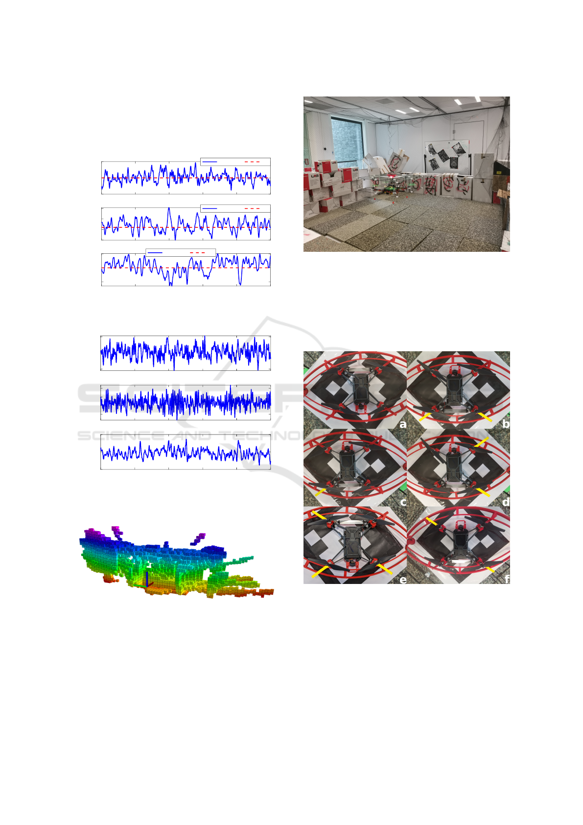
for transportation flight path planning. As shown in
Figure 7, the real-time updated 3D occupancy 10cm-
resolution mapping is generated with the OctoMap
framework in a lab environment depicted in Figure
8.
0 20 40 60 80 100
0.35
0.4
0.45
x [m]
odometry ref
0 20 40 60 80 100
-0.1
-0.05
0
0.05
y [m]
odometry ref
0 20 40 60 80 100
time [s]
0.8
0.85
0.9
z [m]
odometry ref
Figure 5: Hover flight test with odometry.
0 20 40 60 80 100
-0.1
0
0.1
roll [rad]
0 20 40 60 80 100
-0.05
0
0.05
0.1
pitch [rad]
0 20 40 60 80 100
time [s]
55
60
65
thrust [N]
Figure 6: Roll, pitch, and thrust command for the aerial
carrier.
Figure 7: 3D occupancy map with OctoMap framework.
4.2 Anchor Test
To test the the effectiveness and reliability of the an-
chor system, firstly we configure different numbers
of companion UAV feet grabbed as shown in Figure
9. Subject to each configuration of the number of the
feet grabbed, we do 30 sampling tests with the car-
Figure 8: Lab environment used for flight experiments.
rier wobbling with pitch and roll angles of 90 degrees
respectively, and the results of locking success rate
with different numbers of feet grabbed are presented
in Figure 10 which indicates that with more than 2
feet grabbed the locking performance is reliable and
sufficient for our application.
Figure 9: Grabbed feet configurations. The feet that are not
held by the arms are highlighted in yellow. a) shows all feet
are successfully grabbed by the arms. c) shows only one
foot being grabbed. e) shows three feet being grabbed. b),
d), and f) present varying two feet configurations.
With reference to the previous UAV landing re-
search in Table 4, the landing error can be less than
8cm and the corresponding requirement of the dock-
ing platform profile and size of the companion UAV
is included in our design of the docking platform and
ROBOVIS 2021 - 2nd International Conference on Robotics, Computer Vision and Intelligent Systems
108
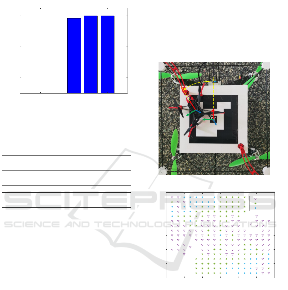
0 1 2 3 4
feet grabbed
0
20%
40%
60%
80%
100%
locking success rate
100% 100%
96.7%
0 0
Figure 10: Locking success rate with different number of
the feet grabbed.
the choice of the companion UAV.
Table 4: Landing errors of various state-of-the-art UAV
landing methods.
Methods Landing error (cm)
(Yang et al., 2014) 1.5
(Cocchioni et al., 2014) 2.0
(Benini et al., 2016) 2.0
(Yu et al., 2017) 0.4
(Alvarez Custodio, 2019) 7.8
(Sani and Karimian, 2017) 6.0
To obtain the proper docking orientation in yaw
and find the better docking success rate, the docking
anchoring experiments on the ground are conducted
when the companion UAV with four anchor feet docks
on the docking fractal marker board with a yaw an-
gle of 0 degrees, 30 degrees, and 45 degrees, respec-
tively, and the coordinate system of the companion
UAV and docking platform are described in Figure 11.
As shown in Figure 12 for experiments with a docking
yaw angle of 0 degrees, the maximum docking center
offset can reach ±8cm with the rotational symmetry
test data mirroring, but only 52.7% of the samples are
grabbed by three or four feet, and based on the results
in Figure 10 and Table 4, it suggests that the compan-
ion UAV can reliably dock with the yaw angle of 0
degrees and offset ±8cm. The experiment results of
docking with a yaw angle of 30 degrees are shown in
Figure 13, and the samples grabbed with three or four
feet occupy around 96.67% but the maximum docking
center offset is only around ±6.5cm. Moreover, the
results of docking with a yaw angle of 45 degrees are
presented in Figure 14 and all the sampling cases are
grabbed with three or four feet, but the the maximum
docking center offset is only around ±6.7cm. Based
on the results of the three cases above, it indicates that
docking with a yaw angle of 45 degrees is relatively
reliable and robust, but its docking available area is
small, which requires higher landing accuracy for the
companion UAV. Specially noted, if the companion
UAV is grabbed with more than two feet during flight
tests, it will be automatically centered by the drone’s
high-frequency shaking and the force applied by the
two servo motors.
yaw
Figure 11: Coordinate system.
-9 -6 -3 0 3 6 9
x [cm]
-9
-6
-3
0
3
6
9
y [cm]
2 feet
3 feet
4 feet
Figure 12: Companion UAV grab test with yaw angle of 0
degrees.
In mechanic design, we adapt a net protection
structure to ensure the safety of the carrier when the
docking fails on the tag board. We intentionally place
the drone with yaw angle of 0 degrees on sampling
points of the nets protection structure while the drone
is wobbling with pitch and roll angles of 45 degrees
respectively to test its ability to hold the compan-
ion UAV in place in order to demonstrate its fault-
tolerance. The result is displayed in Figure 15.
It suggests that the companion UAV docking with
error of around ±0.35m can be safe and will not de-
stroy the carrier, docking platform or itself.
An Unmanned Aerial Carrier and Anchoring Mechanism for Transporting Companion UAVs
109
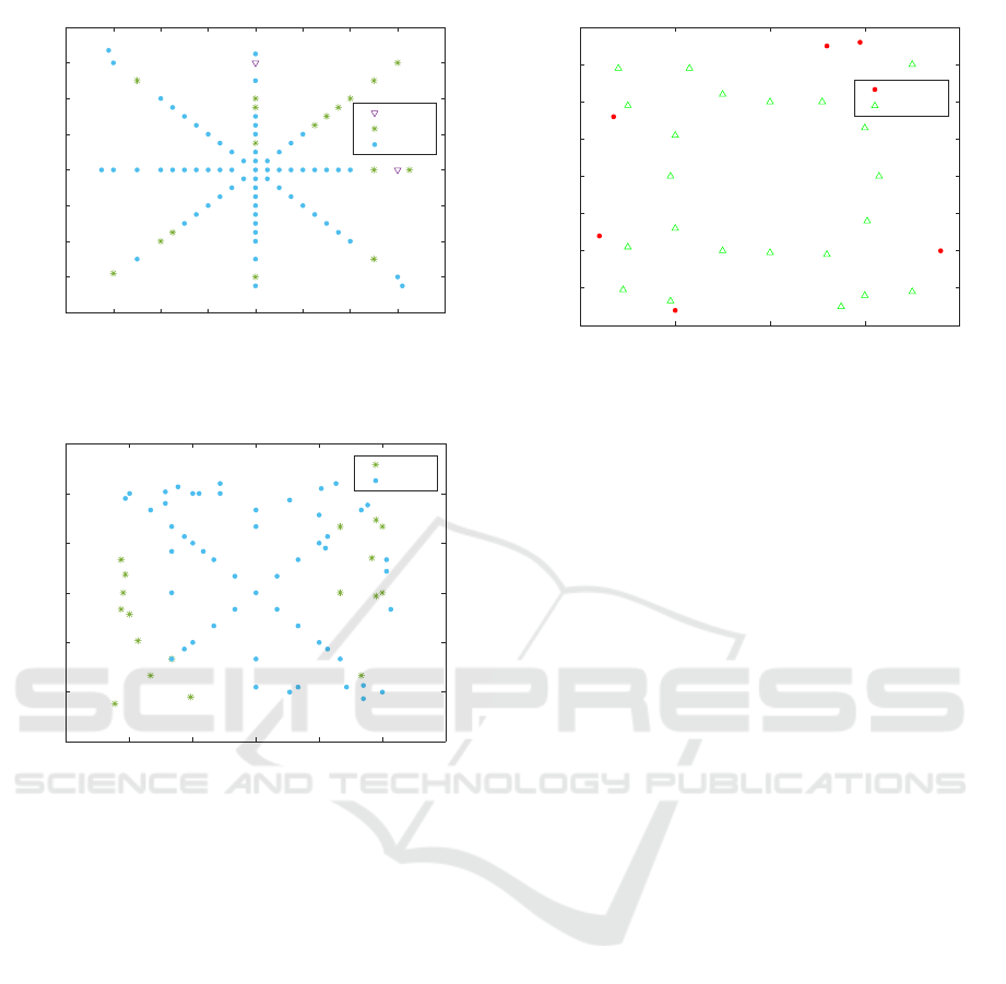
-8 -6 -4 -2 0 2 4 6 8
x [cm]
-8
-6
-4
-2
0
2
4
6
8
y [cm]
2 feet
3 feet
4 feet
Figure 13: Companion UAV grab test with yaw angle of 30
degrees.
-9 -6 -3 0 3 6 9
x [cm]
-9
-6
-3
0
3
6
9
y [cm]
3 feet
4 feet
Figure 14: Companion UAV grab test with yaw angle of 45
degrees.
5 CONCLUSIONS
In this paper, we present the system design of an
aerial carrier and anchoring platform for transporting
a companion UAV. To fulfill the aerial carrier flight
implementation, an aerial system including precise
localization, environment perception, and flight con-
trol framework was developed and implemented in
an indoor lab environment. Subject to the anchoring
platform, we designed a customized lightweight an-
chor system to lock the companion UAV and a fault-
tolerant protection structure to ensure the docking se-
curity. The effectiveness and reliability of them are
validated by the experiments with different configu-
rations of feet grabbed and docking orientations. The
future work will focus on the outdoor real-world in-
flight companion UAV docking experiments with our
aerial carrier and anchoring platform.
-40 -20 0 20 40
x [cm]
-40
-30
-20
-10
0
10
20
30
40
y [cm]
failure
success
Figure 15: Nets docking fault-tolerance test.
ACKNOWLEDGEMENTS
This research received financial support by a Luik-3
grant on advanced brain-robot interfaces.
REFERENCES
Afrisal, H., Rahmadani, T., Nugroho, W. D., Putra, D. A.,
et al. (2019). Inertial navigation system of quadrotor
based on imu and gps sensors. In 2019 6th Interna-
tional Conference on Information Technology, Com-
puter and Electrical Engineering (ICITACEE), pages
1–6. IEEE.
Alvarez Custodio, M. (2019). Autonomous recharging sys-
tem for drones: Detection and landing on the charging
platform.
Benini, A., Rutherford, M. J., and Valavanis, K. P. (2016).
Real-time, gpu-based pose estimation of a uav for
autonomous takeoff and landing. In 2016 IEEE In-
ternational Conference on Robotics and Automation
(ICRA), pages 3463–3470. IEEE.
Bloesch, M., Burri, M., Omari, S., Hutter, M., and Sieg-
wart, R. (2017). Iterated extended kalman filter
based visual-inertial odometry using direct photomet-
ric feedback. The International Journal of Robotics
Research, 36(10):1053–1072.
Carlos, B. B., Sartor, T., Zanelli, A., Frison, G., Burgard,
W., Diehl, M., and Oriolo, G. (2020). An efficient
real-time nmpc for quadrotor position control under
communication time-delay. In 2020 16th Interna-
tional Conference on Control, Automation, Robotics
and Vision (ICARCV), pages 982–989. IEEE.
Cocchioni, F., Mancini, A., and Longhi, S. (2014). Au-
tonomous navigation, landing and recharge of a
quadrotor using artificial vision. In 2014 international
conference on unmanned aircraft systems (ICUAS),
pages 418–429. IEEE.
Daudelin, J., Jing, G., Tosun, T., Yim, M., Kress-Gazit, H.,
and Campbell, M. (2018). An integrated system for
ROBOVIS 2021 - 2nd International Conference on Robotics, Computer Vision and Intelligent Systems
110

perception-driven autonomy with modular robots. Sci-
ence Robotics, 3(23).
Garrido-Jurado, S., Munoz-Salinas, R., Madrid-Cuevas,
F. J., and Medina-Carnicer, R. (2016). Generation of
fiducial marker dictionaries using mixed integer linear
programming. Pattern Recognition, 51:481–491.
Hornung, A., Wurm, K. M., Bennewitz, M., Stachniss,
C., and Burgard, W. (2013). OctoMap: An effi-
cient probabilistic 3D mapping framework based on
octrees. Autonomous Robots. Software available at
http://octomap.github.com.
Jain, K. P. and Mueller, M. W. (2020). Flying batter-
ies: In-flight battery switching to increase multirotor
flight time. In 2020 IEEE International Conference on
Robotics and Automation (ICRA), pages 3510–3516.
IEEE.
Jain, K. P., Park, M., and Mueller, M. W. (2020). Docking
two multirotors in midair using relative vision mea-
surements. arXiv preprint arXiv:2011.05565.
Kamel, M., Burri, M., and Siegwart, R. (2016). Linear
vs Nonlinear MPC for Trajectory Tracking Applied to
Rotary Wing Micro Aerial Vehicles. ArXiv e-prints.
Kamel, M., Stastny, T., Alexis, K., and Siegwart, R. (2017).
Model predictive control for trajectory tracking of un-
manned aerial vehicles using robot operating system.
In Koubaa, A., editor, Robot Operating System (ROS)
The Complete Reference, Volume 2. Springer.
Lee, T., Leok, M., and McClamroch, N. H. (2010). Geo-
metric tracking control of a quadrotor uav on se (3). In
49th IEEE conference on decision and control (CDC),
pages 5420–5425. IEEE.
Lin, Y., Gao, F., Qin, T., Gao, W., Liu, T., Wu, W., Yang,
Z., and Shen, S. (2018). Autonomous aerial naviga-
tion using monocular visual-inertial fusion. Journal
of Field Robotics, 35(1):23–51.
Lin, Y.-C., Cheng, Y.-T., Zhou, T., Ravi, R., Hasheminasab,
S. M., Flatt, J. E., Troy, C., and Habib, A. (2019).
Evaluation of uav lidar for mapping coastal environ-
ments. Remote Sensing, 11(24):2893.
Loianno, G., Spurny, V., Thomas, J., Baca, T., Thakur, D.,
Hert, D., Penicka, R., Krajnik, T., Zhou, A., Cho, A.,
et al. (2018). Localization, grasping, and transporta-
tion of magnetic objects by a team of mavs in chal-
lenging desert-like environments. IEEE Robotics and
Automation Letters, 3(3):1576–1583.
Lutz, P., M
¨
uller, M. G., Maier, M., Stoneman, S., Tomi
´
c, T.,
von Bargen, I., Schuster, M. J., Steidle, F., Wedler,
A., St
¨
urzl, W., et al. (2020). Ardea—an mav with
skills for future planetary missions. Journal of Field
Robotics, 37(4):515–551.
Narv
´
aez, E., Ravankar, A. A., Ravankar, A., Emaru, T., and
Kobayashi, Y. (2020). Autonomous vtol-uav dock-
ing system for heterogeneous multirobot team. IEEE
Transactions on Instrumentation and Measurement,
70:1–18.
Narv
´
aez, E., Ravankar, A. A., Ravankar, A., Kobayashi,
Y., and Emaru, T. (2017). Vision based autonomous
docking of vtol uav using a mobile robot manipula-
tor. In 2017 IEEE/SICE International Symposium on
System Integration (SII), pages 157–163. IEEE.
Peng, K., Du, J., Lu, F., Sun, Q., Dong, Y., Zhou, P., and
Hu, M. (2019). A hybrid genetic algorithm on routing
and scheduling for vehicle-assisted multi-drone parcel
delivery. IEEE Access, 7:49191–49200.
Perez-Grau, F. J., Caballero, F., Merino, L., and Viguria,
A. (2017). Multi-modal mapping and localization
of unmanned aerial robots based on ultra-wideband
and rgb-d sensing. In 2017 IEEE/RSJ International
Conference on Intelligent Robots and Systems (IROS),
pages 3495–3502. IEEE.
Qin, T., Li, P., and Shen, S. (2018). Vins-mono: A robust
and versatile monocular visual-inertial state estimator.
IEEE Transactions on Robotics, 34(4):1004–1020.
Qin, T. and Shen, S. (2018). Online temporal calibration for
monocular visual-inertial systems. In 2018 IEEE/RSJ
International Conference on Intelligent Robots and
Systems (IROS), pages 3662–3669. IEEE.
Rocha, R. and Robinson, S. K. (2020). Toward autonomous
in-flight docking of unmanned multi-rotor aerial vehi-
cles. In AIAA Scitech 2020 Forum, page 1486.
Romero-Ramire, F. J., Munoz-Salinas, R., and Medina-
Carnicer, R. (2019). Fractal markers: a new approach
for long-range marker pose estimation under occlu-
sion. IEEE Access, 7:169908–169919.
Romero-Ramirez, F. J., Mu
˜
noz-Salinas, R., and Medina-
Carnicer, R. (2018). Speeded up detection of squared
fiducial markers. Image and vision Computing,
76:38–47.
Sa, I., Kamel, M., Khanna, R., Popovi
´
c, M., Nieto, J., and
Siegwart, R. (2018). Dynamic system identification,
and control for a cost-effective and open-source multi-
rotor mav. In Field and Service Robotics, pages 605–
620. Springer.
Sani, M. F. and Karimian, G. (2017). Automatic naviga-
tion and landing of an indoor ar. drone quadrotor us-
ing aruco marker and inertial sensors. In 2017 interna-
tional conference on computer and drone applications
(IConDA), pages 102–107. IEEE.
Tzoumanikas, D., Li, W., Grimm, M., Zhang, K., Kovac,
M., and Leutenegger, S. (2019). Fully autonomous
micro air vehicle flight and landing on a moving target
using visual–inertial estimation and model-predictive
control. Journal of Field Robotics, 36(1):49–77.
Ullah, N., Mehmood, Y., Aslam, J., Ali, A., and Iqbal, J.
(2021). Uavs-ugv leader follower formation using
adaptive non-singular terminal super twisting sliding
mode control. IEEE Access, 9:74385–74405.
Wasim, M., Ullah, M., and Iqbal, J. (2019). Gain-scheduled
proportional integral derivative control of taxi model
of unmanned aerial vehicles. Revue Roumaine des
Sciences Techniques-Serie Electrotechnique et Ener-
getique, 64(1):75–80.
Yang, S., Scherer, S. A., Schauwecker, K., and Zell, A.
(2014). Autonomous landing of mavs on an arbitrarily
textured landing site using onboard monocular vision.
Journal of Intelligent & Robotic Systems, 74(1):27–
43.
Yu, C., Cai, J., and Chen, Q. (2017). Multi-resolution visual
fiducial and assistant navigation system for unmanned
An Unmanned Aerial Carrier and Anchoring Mechanism for Transporting Companion UAVs
111

aerial vehicle landing. Aerospace Science and Tech-
nology, 67:249–256.
Yu, K., Budhiraja, A. K., and Tokekar, P. (2018). Al-
gorithms for routing of unmanned aerial vehicles
with mobile recharging stations. In 2018 IEEE In-
ternational Conference on Robotics and Automation
(ICRA), pages 5720–5725. IEEE.
Zhang, J. and Singh, S. (2014). Loam: Lidar odometry
and mapping in real-time. In Robotics: Science and
Systems, volume 2.
ROBOVIS 2021 - 2nd International Conference on Robotics, Computer Vision and Intelligent Systems
112
