
Evaluation of an Artificial Potential Field Method in Collision-free
Path Planning for a Robot Manipulator
M. Elahres
a
, A. Fonte
b
and G. Poisson
c
PRISME Laboratory, University of Orléans - INSA Centre-Val de Loire, Orléans, France
Keywords: Collision-free Local Path Planning, Artificial Potential Field, Hollow Cylindrical Obstacle Avoidance,
Position and Orientation Path Planning, Virtual Force and Torque-based Reactive Control.
Abstract: Path planning with obstacle avoidance has been a major challenge in robotic manipulators which are
composed of multiple links especially in the case of complex-shaped obstacles. This paper proposes an
improved collision-free path planning algorithm based on the Artificial Potential Field (APF) method to obtain
a collision-free path from initial to a desired position and orientation. Firstly, the robot is modelled by the
Denavit-Hartenberg DH parameter method. Secondly, the artificial attractive and repulsive force field
equations are derived in the case of both spherical and hollow cylindrical obstacles. Then, a poly-articulated
cylindrical model for the robot is used for collision detection between all its links and the obstacle. Finally, a
virtual torque is generated based on the forces affecting the robot links to produce a suitable motion to
approach the final target without collision with the obstacle. The algorithm is evaluated by building a
simulation platform using MATLAB R2020b and Robotic Toolbox. Various simulations on the UR5 robot
show that the proposed algorithm can plan a free-collision path in the 6D operational space. The simulations
also show that the algorithm has a low computational cost, so it can be used for real-time applications.
1 INTRODUCTION
Robotic technologies have rapidly evolved since the
first industrial robot, Unimate 001, introduced in the
mid-twentieth century. In robot systems design, in
addition to technological choices, the questions of
robot enrolment, workspace adaptation, aspects
choices, path planning generation, etc. have always
been major obstacles to robot development. In
particular, the obstacle avoidance issue has been a
major challenge for roboticists.
In some assisted-robot medical applications such
as radiology, the robot has to guide dedicated tools
inside gantries in the form of hollow cylinders, where
patients are located, and do some tools manipulations.
Furthermore, in this framework, the robot needs to get
out from this constrained environment after having
carried out its task. During all these sub-tasks, the
complex poly-articulated robot mechanism has to
avoid collision with the environment’s boundaries.
a
https://orcid.org/0000-0003-2502-1505
b
https://orcid.org/0000-0003-3403-1588
c
https://orcid.org/0000-0002-6730-9411
Due to the physical principles of the medical
devices where the robot operates (CT-scan, PET), the
robot task needs to be done through teleoperation
respecting the following constraints:
1-Environment is partially seen by the operator. 2-
During the teleoperation procedure, the operator, as a
human in the loop, can ensure obstacle avoidance.
However, that is not ensured to succeed all the time
because the operator could commit some errors and
teleoperates the robot terminal organ without looking
at the complete configuration of the articulated
mechanism. Besides that, telecommunication failure
or delay might lead to a collision. 3- Since focusing
on obstacle avoidance causes the operator to lose
concentration on the main task, it is preferable to
assign the obstacle avoidance sub-task to an
automatic and safe controller.
For the reasons above, and to increase safety, an
automatic algorithm to ensure collision-free path
planning during teleoperation is unavoidable.
92
Elahres, M., Fonte, A. and Poisson, G.
Evaluation of an Artificial Potential Field Method in Collision-free Path Planning for a Robot Manipulator.
DOI: 10.5220/0010652800003061
In Proceedings of the 2nd International Conference on Robotics, Computer Vision and Intelligent Systems (ROBOVIS 2021), pages 92-102
ISBN: 978-989-758-537-1
Copyright
c
2021 by SCITEPRESS – Science and Technology Publications, Lda. All rights reserved

At present, there are many methods for obstacle
avoidance in path planning of manipulators, including
C-space methods, Artificial Potential Field (APF),
force field, visibility graph, pre-processing-planning
algorithm, topology method, or fuzzy logic algorithm
(Chotiprayanakul et al., 2007; Gasparetto et al., 2015;
Jiang et al., 2018; lajpah & Petri, 2012; Petrič et al.,
2015). Other methods like minimum seeking
algorithms, genetic algorithms, and spline-based
algorithms can be found with a discussion on
trajectory planning in (Iqbal et al., 2016). These
methods can be classified into two main categories:
global and local ones. Global methods are devoted to
finding a collision-free path from the start pose to the
goal pose if such a path exists. However, they are
computationally heavy and therefore not applicable
for real-time control (Kivelä et al., 2017).
Since our focus is on local planning to avoid
collision in structured environments, we chose to use
reactive control methods like APF which is faster
than other numerical Jacobian-based inverse
kinematics methods (Park et al., 2020a). And also
APF was noted by Hoy in (Hoy et al., 2015) to be
faster than other local planning methods.
One of the most important procedures to perform
before collision avoidance, is measuring distance
between the robot manipulator and the obstacle to
determine the possibility of collisions. Since
computing this distance using accurate topology is
very time consuming, many researchers have been
trying to find efficient approaches to speed up the
calculation. For example, covering the links of a robot
manipulator with polytope, polyhedron, sphere,
ellipsoid, etc. which can significantly reduce
computing time (Chotiprayanakul et al., 2007).
As far as we know, no previous research has
investigated path planning inside hollow shaft
cylindrical obstacles. However, only a few studies
proposed algorithms to detect cylinders (Chittawadigi
& Saha, 2013; J. Ketchel & Larochelle, 2006; J. S.
Ketchel & Larochelle, 2005; Michael, 2010). In all
these works, the obstacles were occluded, the planned
paths had to be outside them, and the repulsive field
has unique distribution in contrast to our situation.
This paper presents a dedicated method to
collision-free local path planning and its validation
through simulation. This method is developed based
on the artificial potential field concept to avoid
collision with a whole robot manipulator. And it
proposes a repulsive field model for hollow
cylindrical obstacles. The robot was modeled with
poly-articulated cylinders in the obstacle detection.
In the next section, we first give a model of the
robot. On the basis of this model, a collision-free path
is planned using the artificial potential field, the
algorithm is explained in case of general obstacle.
Then, hollow cylindrical obstacles were processed.
Finally, the algorithm is verified through simulation.
2 THE PROPOSED METHOD
2.1 The Robot Model
This study is based on the integration of the UR5
cobot from Universal Robots company which is a
lightweight 6 degree-of-freedom (DoF) robot
designed for safe direct interaction.
From the Universal Robots datasheet, we defined
the modified Denavit-Hartenberg (D-H) parameters
(Universal Robots, 2020) given in Table 1. More
information about both modified D-H table and UR5
kinematics is found in (Diab et al., 2020; Ullah et al.,
2014) and (Kufieta, 2014) respectively.
The reference frame R
0
(O
0
, x
0
, y
0
, z
0
) of the
environment is located at the base of the robot were
z
0
axis is vertical and the origin O
0
is placed on the
bottom plane of the robot. We chose not to take into
account the translation of origin along the z
0
axis that
Universal Robots integrated in its Polyscope device
as it is a software issue. This explains the value
89.159 mm for d
1
that can differs in others papers.
Table 1: Modified Denavit-Hartenberg table (DHm) for the
6 DoF UR5 robot. Parameters are given in mm and rad.
Link i a
i-1
α
i-1
d
i
1 0 0 89.159
20π/2 0
3 - 425 0 0
4 -392.25 0 109.15
5 0 π/2 94.65
6 0 -π/2 82.3
With respect to the DHm approach, the
homogeneous transformation between the nearby
frames R
i
and R
i-1
is given in the next 4x4 matrix
(Reddy, 2014).
𝑇
𝑐𝜃
𝑠𝜃
0 𝑎
𝑠𝜃
.𝑐𝛼
𝑐𝜃
.𝑐𝛼
𝑠𝛼
𝑑
.𝑠𝛼
𝑠𝜃
.𝑠𝛼
0
𝑐𝜃
.𝑠𝛼
0
𝑐𝛼
0
𝑑
.𝑐𝛼
1
With, c and s denote repectively cosinus and sinus.
The global transformation
0
T
6
relation is:
0
T
6
=
0
T
1
.
1
T
2
.
2
T
3
.
3
T
4
.
4
T
5
.
5
T
6
(1)
The above transformations were used in order to
compute the 6x6 Jacobian matrix of the
transformation and robot links extremities positions.
Evaluation of an Artificial Potential Field Method in Collision-free Path Planning for a Robot Manipulator
93

These particular points afterwards are used in the
algorithm. In addition, the algorithm evaluates and
uses the Jacobian matrices at certain critical points
precomputed during the execution, which obliges us
to express the general form of Jacobian inspired by
(Kufieta, 2014; Spong et al., 2006) as follows:
𝑤
𝑣
𝐽
𝑞 (2)
Where 𝑣
and 𝑤
are the linear and the angular
velocity vector of the end effector frame R
n
expressed
in inertial frame R
0
, respectively.
In this case, the Jacobian 𝐽
is given by:
𝐽
(3)
In case of fully revolute manipulator, the upper
and lower half of the Jacobian are given as:
𝐽
𝑧
…𝑧
(4)
𝐽
𝑧
𝑂
𝑂
…𝑧
𝑂
𝑂
(5)
𝐽
𝑧
… 𝑧
𝑧
𝑂
𝑂
… 𝑧
𝑂
𝑂
(6)
With z
n
and O
n
: the z axis and the origine of frame R
n
.
We can get the Jacobian at an arbitrary robot point
located on link 𝑗 by replacing 𝑂
with the position of
the arbitrary point and setting the last 𝑛𝑗 columns
to
0…0
as described below.
Let 𝑟
a vector pointing to an arbitrary point P on
link 𝑗, expressed in the inertial frame R
0
, the Jacobian
𝐽
is then (Kufieta, 2014):
𝐽
𝑧
… 𝑧
0…0
𝑧
𝑟
𝑂
… 𝑧
𝑟
𝑂
0…0
(7)
2.2 Proposed Collision-free Path
Planning Algorithm
The Artificial Potential Field (APF) is a traditional
path planning method proposed by Khatib (1985) to
ensure real time obstacle avoidance for a mobile robot
and has made a great achievement as a path planning
method for robotic arms. The basic idea of APF is to
make the robot move toward the target while being
influenced by the attractive and repulsive forces
which are generated from the target and the obstacle,
respectively. During the procedure, the robot starts
from the initial position and moves along the potential
field's descent path to reach the target point. The
potential functions are designed as follows:
The force generated from attractive potential:
𝐹
𝑘
,
𝑃
𝑃
(8)
Where 𝐹
,𝑘
,
,𝑃
,𝑃
are the virtual attractive
force, proportional coefficient, target position and
current position of the end effector, respectively. In
order to plan the orientation of the end effector, we
define a virtual momentum to affect the orientation of
the end effector as follows:
𝑀
𝑘
,
𝑒
(9)
Where 𝑀
,𝑘
,
, 𝑒
are the virtual attractive
momentum, proportional coefficient and orientation
error, respectively. Direct computation of the
orientation error requires the use of the Euler angles
which suffers from representation singularities. To
overcome this drawback, this error is calculated based
on unit quaternion representation. Let 𝑄
𝜂
, 𝜀
be the quaternion defined by the target orientation of
the robot end effector. 𝜂
, 𝜀
are the scalar and the
vector parts of 𝑄
, respectively. And 𝑄
𝜂
, 𝜀
the quaternion defined by the current
orientation. 𝜂
, 𝜀
are the scalar and the vector parts
of 𝑄
, respectively. Then the orientation error is given
by this equation (Aguilar & Sidobre, 2006; Campa &
Camarillo, 2008)(Kivelä et al., 2017):
𝑒
𝜂
𝜀
𝜂
𝜀
𝑆𝜀
𝜀
(10)
Where 𝑆𝜀
is the skew-symmetric matrix for the 𝜀
.
Then, the attractive torque affecting all the joints
can be calculated using the Jacobian 𝐽:
𝑇
𝐽
𝑀
𝐹
(11)
To detect the distance to the obstacle, each robot link
is considered a cylinder. Then each cylinder axis is
divided into a certain number of points. After that, the
distance between each point of those and the obstacle
is measured to determine the nearest point from each
link to the obstacle. if the latest point is in the range
of the repulsive field, then it is considered as a critical
point and a repulsive force is assigned to it. We
propose the expression of the force generated from
repulsive potential at one critical point as:
F
,
k
1
‖
∆X
‖
P
,
P
,
P
,
P
,
(12)
Where F
,
,𝑘
,P
,
,P
,
,
‖
∆X
‖
are the virtual
repulsive force affecting critical point i, a
proportional coefficient, the critical point i on the
robot and nearest point on the obstacle to the critical
ROBOVIS 2021 - 2nd International Conference on Robotics, Computer Vision and Intelligent Systems
94
point on the robot, and the distance between critical
point i and nearest point on the obstacle respectively.
The poly-articulated robot is a highly coupled
structure, and the repulsive force generated from the
obstacle on a single critical point affects other joints.
We pass the repulsion force of a single critical
point to other joints through the Jacobian matrix at
that critical point. Then adding all effects on the joints
(Eq.13) we get what we call virtual repulsive torque
generated from the obstacle and affecting the robot
joints using the formula of Park et al., (2020b) after
modifying it to suite our study.
T
J
,
F
,
(13)
After computing the virtual attractive and repulsive
torques, we add them to get the total torque affecting
the robot joints (Eq.14).
𝑇𝛼
𝑇
𝛼
T
(14)
We propose weights 𝛼
, 𝛼
to variate the
priorities between target tracking and obstacle
avoidance. In case the end effector is too far from the
target and there is no existence of obstacle (or the
obstacle is far), the algorithm gives high values for
𝛼
. At the opposite if the obstacle is too close to
some points of the robot then the priority is given to
avoiding the obstacle and the 𝛼
takes high values.
In order to have natural behavior for the robot
when avoiding the obstacle, we need to give great
priority to joints which affect directly the critical
points near the obstacle so we propose to choose 𝛼
inversely proportional to the distance between critical
points and obstacle. Then we use the Jacobian at those
critical points to pass from this distance vector to
robot joints as proposed in (Eq.15).
α
J
,
1
dx
1
d
y
1
dz
(15)
After getting total torque value 𝑇, we compute an
increment in the robot state vector q as follows (Park
et al., 2020b):
𝑑𝑞𝐶
𝑇
‖
𝑇
‖
(16)
Where 𝐶 is constant. Then we update the robot state:
𝑞
𝑞
𝑑𝑞
(17)
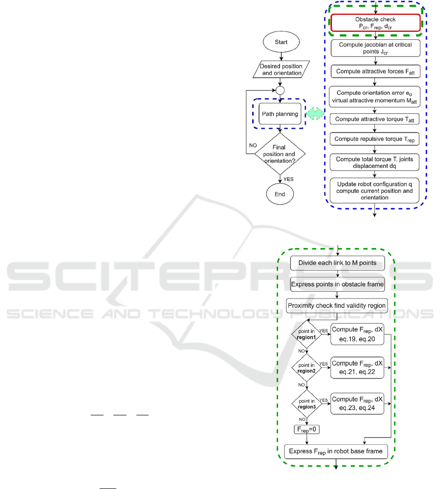
Figure 1 describes the algorithm. In the left
column, a general overview of the algorithm is
presented. The right one describes in more detail the
path planning algorithm. Figure 2 describes, also in
more detail the algorithm of obstacle avoidance in
case of a cylindrical obstacle.
Figure 1: Obstacle avoidance path planning flow chart.
Figure 2: Cylindrical obstacle check flow chart.
2.2.1 General Obstacle Case
The following Figures (3 to 6) visualize how the robot
moves from an initial state (position and orientation)
to a final state without colliding with the obstacle by
the effect of attractive and repulsive forces.
Figure 3 shows the robot in three different states.
Evaluation of an Artificial Potential Field Method in Collision-free Path Planning for a Robot Manipulator
95
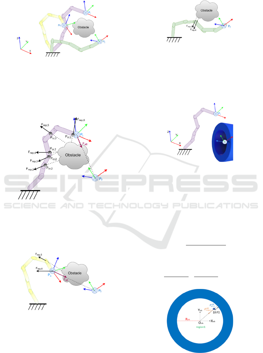
Figure 3: Robot manipulator motion in the presence of an
obstacle. The robot is represented in the initial (purple),
intermediate (yellow) and final state (green).
Figure 4 visualizes the different forces affecting
the robot in a given state. We can notice that in this
state, link2, link3, link4, link5, link6 are affected by
repulsive forces because they are close to the obsacle.
Figure 4: Repulsive and attractive forces affecting the robot
in the initial position (link2 to link6 are in the effective field
of the obstacle).
The total virtual torque led the robot to an
intermediate state that makes it approaches the final
target without colliding with the obstacle (Figure 5).
Figure 5: The robot in an intermediate position during its
motion (only link5 and link6 are in the effective field of the
obstacle).
Finally, the robot reaches the target position and
orientation (Figure 6). If there is still some links in the
range of the obstacle, the robot still tries to change its
configuration in order to cancel the repulsive forces.
Figure 6: The robot at the final position (there is no
attractive force but the repulsive forces move link3 and
link4 away from the obstacle).
2.2.2 Hollow Cylindrical Obstacle Case
Figure 7 shows the robot near an obstacle in the forme
of a cylindrical gantry.
Figure 7: Manipulator motion in the presence of a hollow
cylindrical obstacle (gantry).
In order to easily define an artificial potential field
function, we made benefit from the cylindrical
symmetry of the obstacle. We proposed to consider
three main regions according to the tested point
position in relative to the gantry:
1- Region1: inside gantry (Figure 8):
𝑃
,
𝑇
𝑃
,
𝑋
,
𝑌
,
𝑍
,
(18)
‖
∆𝑋
‖
𝑅
𝑋
,
𝑌
,
(19)
𝐹
,
𝑘
1
𝑅
𝑋
,
1
𝑅
𝑌
,
0
(20)
Figure 8: Cross section for the gantry shows repulsive force
elements affecting a critical point inside the gantry.
ROBOVIS 2021 - 2nd International Conference on Robotics, Computer Vision and Intelligent Systems
96
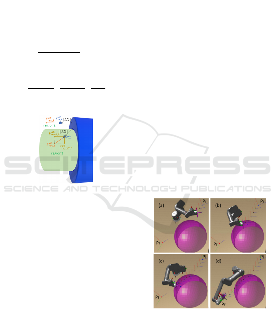
2- Region2: outside the gantry, outside the extension
(Figure 9)
𝐹
,
𝑘
00
1
𝑍
,
(21)
‖
∆𝑋
‖
𝑍
,
(22)
3- Region3: outside the gantry, inside the extension
(Figure 9)
‖
∆𝑋
‖
𝑅
𝑋
,
𝑌
,
𝑍
,
(23)
𝐹
,
𝑘
1
𝑅
𝑋
,
1
𝑅
𝑌
,
1
𝑍
,
(24)
𝐹
,
𝑇
𝐹
,
(25)
Figure 9: Repulsive forces elements affecting critical points
outside the gantry in two cases (inside and outside the green
extension).
3 SIMULATION RESULTS AND
DISCUSION
Measuring the viability of a real-time collision- free
path planning is very complicated, due to the difficult
algorithm effectiveness validation in reason of the
large number of tests that needed to be done. In
addition, when avoiding obstacles in real-time, the
manipulator could endure some damages if a collision
is unavoidable. Therefore, a simulation platform for
the purpose of the whole-arm obstacle avoidance path
planning of the arm in the obstacle space was
established in respond for the above problematics.
The simulation platform uses MATLAB R2020b in
conjunction with Robotics Toolbox.
We created the robot model starting from the
parameters given in table1. Then, we performed all
necessary functions to compute the direct kinematic,
jacobian matrices, collision detection and path
planning. Inverse kinematic is not needed in the
algorithm. But, it was used in the initialization in
some tests. For this reason, it was computed using the
inverse kinematic solver which is included in
MATLAB Robotics Toolbox when it was needed.
To do the visualizations, we used the interactive
rigid body tree which provides both: an easy way to
change the robot configuration on the figure, and an
easy way to add obstacles to the environment. UR5
robot 3D model contained in MATLAB libraries was
used. In order to enable the robot to overcome the
obstacle while moving towords the desired position
and orientation, our proposed algorithm adds the
effects of all the attractive/repulsive forces affecting
the robot links as a total torque.
The simulation experiments were separated into
two parts: the avoidance of a spherical obstacle, and
the avoidance of a hollow cylindrical obstacle.
3.1 Spherical Obstacle
Table 2 contains the details of this first experiment.
Figure 10 shows simulation results of the
avoidance of a spherical shaped obstacle. The blue
point Pi , the red point Pf and the black points denote
the robot initial, final and planned positions,
respectivley. The orientaion of the robot was
represented using frames (shown in RGB color base).
We can see from these results how the robot
successfully avoided the collision with the obstacle
and reached the final position and orientation.
Figure 10: The robot avoids colliding with a spherical
obstacle. (a) the robot follows the path toward the final
target before reaching the obstacle repulsive field; (b) the
robot reaches the obstacle repulsive field and modifies its
path; (c) the robot begins to get out of the repulsive filed of
the obstacle; (d) the robot reaches the desired position and
orientation.
Evaluation of an Artificial Potential Field Method in Collision-free Path Planning for a Robot Manipulator
97
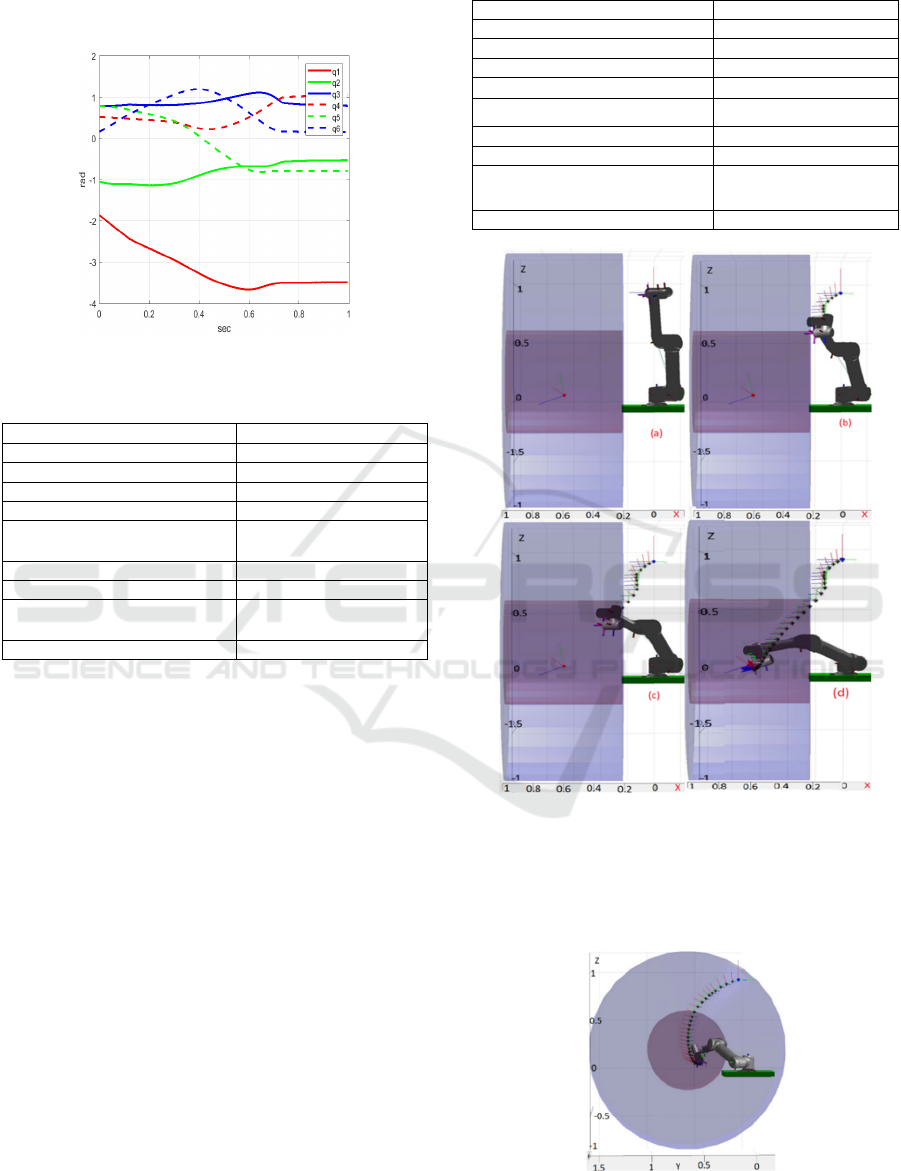
Figure 11 shows the robot joint angles. As this
figure shows, the algorithm generated a smooth path
in the configuration space.
Figure 11: Joint trajectories in sperical obstacle case.
Table 2: Spherical obstacle experiment details.
Shape of obstacle sphere
Coordinates of obstacle (m) (0.45, 0.4, 0.1)
Radius of obstacle (m) 0.3
Starting position (m) (0.01, 0.65, 0.45)
Starting orientation (rad) (-2.68, -0.34, 1.77)
Starting joint angles (rad)
(-/1.7, -/3, /4, /6,
/4, /20)
Desired position (m) (0.66, -0.06, 0.23)
Desired orientation (rad) (-1.96,-0.8,0.21)
Desired joint angles (rad)
(-/0.9, -/6,/4,/3, -
/4,/20)
Calculation time (sec) 0.001
3.2 Hollow Cylindrical Obstacle
(Gantry)
Table 3 contains the details of this second experiment.
Simulation results of the avoidance of a
cylindrical shaped obstacle are shown in Figure12.
The blue point, the red point and the black points
denote the robot initial, final and planned positions,
respectivley. The orientaion of the robot was
represented using frames (shown in RGB color base).
We can see from these results how the robot
successfully avoided the collision with the borders of
the the gantry and reached the final position and
orientation inside the gantry. In Figure13, it is shown
the front view of the environment (Y axis). We can
notice from both Figures 12 and 13 that the path
planned in the operational space of the robot, besides
safely avoiding the collision with the gantry borders,
it was smooth.
Figure 14 shows the robot joint angles. As we can
see from this figure, the algorithm generated a smooth
path in the configuration space.
Table 3: Cylindrical obstacle experiment details.
Shape of obstacle Hollow cylinde
r
Coordinates of obstacle (m) (0.65, 0.6, 0.2)
Internal radius of obstacle (m) 0.5
Starting position (m) (0.024, 0.095, 0.9)
Starting orientation (rad)
(0 , -, 2.62)
Starting joint angles (rad)
(4/3,-/2,0,0,, 0)
Desired position (m) (0.65, 0.44, 0.09)
Desired orientation (rad) (1.09, -0.37, 1.96)
Desired joint angles (rad)
(7/6, -/8, /6, /8, 3
/4, /4)
Calculation time (sec) 0.0013
Figure 12: The robot moves inside the gantry and avoids
colliding with it. (a) the robot at the initial pos before
reaching the obstacle repulsive field; (b) the robot reaches
the obstacle repulsive field and modifies its path; (c) the
robot begins to get out of the repulsive filed of the obstacle;
(d) the robot reaches the desired position and orientation.
Figure 13: Front view for the robot moving inside the gantry
and avoiding colliding with its borders.
ROBOVIS 2021 - 2nd International Conference on Robotics, Computer Vision and Intelligent Systems
98
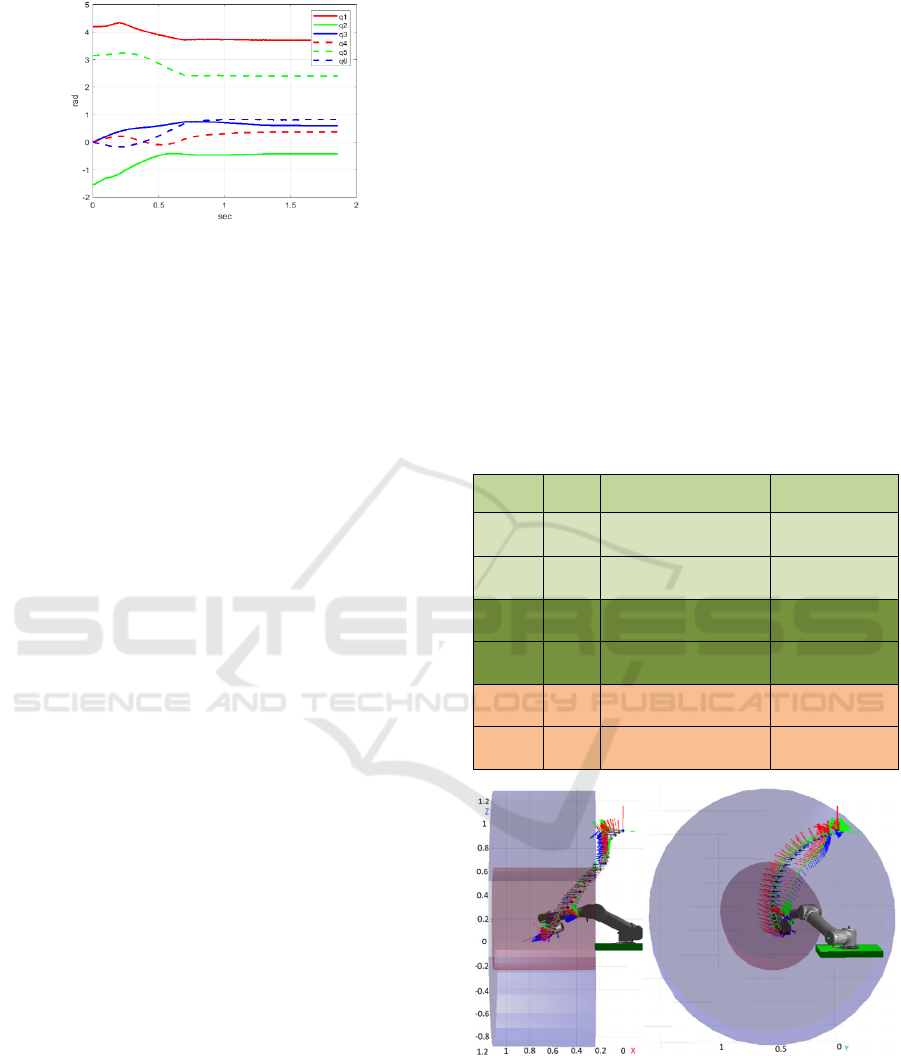
Figure 14: The joint trajectories - cylindrical obstacle.
Figure12 shows that the distance between the end
effector point and the obstacle border is a bout 0.1 m
which is the same as the marginal distance used in the
algorithm. However, it is not always the case, because
the robot links have different values for radius when
they are modeled as poly-articulated cylinders. In
order to ensure the safety, the maximum value for the
radius of these links has to be used as a marginal
distance in the algorithm, although it looses the
manipulability in regions close to the obstacle. It is
worth discussing that by properly tuning constant C
in (Eq.16), a good compromise can be made between
vibration and speed. We noticed that high values for
C lead to high displacement in configuration space,
hence a big vibration. While at the opposite, when
minmizing its value, we can get a more continuous
and smooth path.
Experiments on different configurations for the
initial state of the robot: The proposed algorithm
will be used as part of higher level control system that
supplies initial and final poses to plan a free-collision
path between them. So it is possible that the higher
level system produces another solutions for the
inverse kinematic model of the robot that we used in
our simulation experiment. So we did an experiment
to test the algorithm behaviour when another
solutions for the inverse kinematic are supplied. To
do this, we generated all the possible solutions of the
inverse kinematic at the initial pose (using Inverse
Kinematic Solver in Robotics Toolbox). Then, we
executed the algorithm for each one of these
solutions.
Experiment 1: for the pose given in table 3, we got
multiple solutions for the inverse kinematic because
it is a singular pose, some of them were repeated. We
performed the experiment on the 7 solutions shown in
table4 (it shows that 2 solutions are repeated).
It appeared that the algorithm was able to succeed
in generating a collision-free path for 3 different of
those solutions, and failed in the rest 2 cases. The
failure of the algorithm was due to local minima. But,
it was still successful to avoid the collision despite
slow motion in some places near the obstacle. We
speculate that this might be due to proximity of local
minima that approximately cancels the total torque
affecting robot joints. Figure 15 shows the robot
successfully reachs the desired target with no
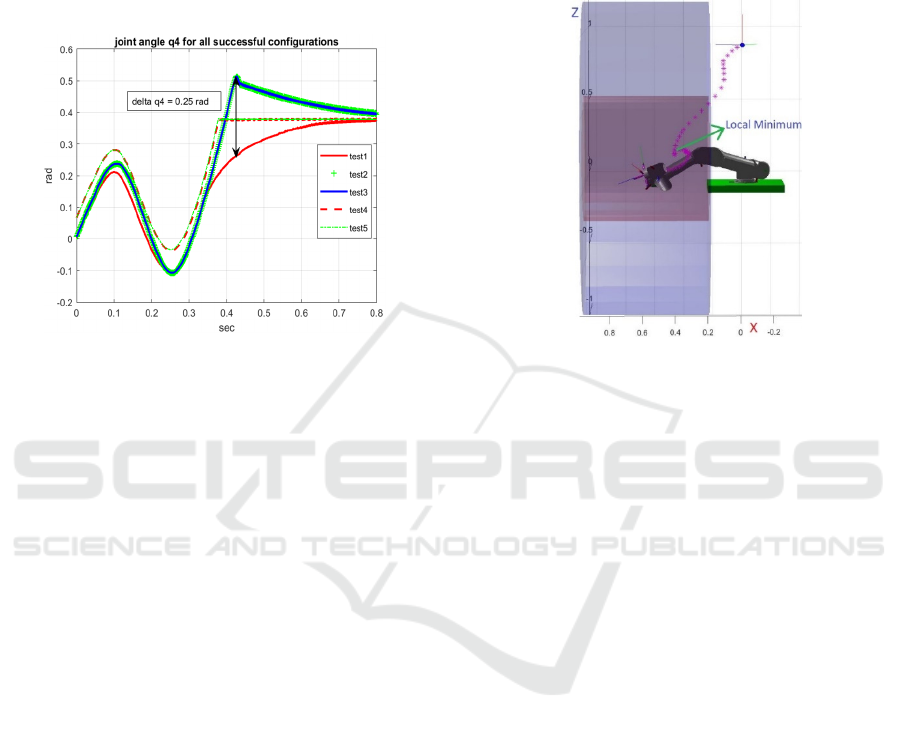
collision (Test1 to Test5). Figure 16 shows joint angle
q4 in successful tests (Test1 to Test5). We can see that
the maximum change in angle value among these
tests is 0.25 rad.
After some processing on the configurations, by
wrapping all articular angles to the inerval [-π,π] and
then deleting the repeated solutions, we found that we
have only 5 different configurations. It is noticed that
configurations 𝑞
,
,𝑞
,
express the same solution.
The same case for the configurations 𝑞
,
,𝑞
,
as
shown in table4.
Table 4: All tested configurations 𝑞
,
for initial robot state
pretested (other details are in table 3).
Test1
𝑞
,
(-2.π/3, - π/2, 0, 0, -π,
0)
successful
Test2
𝑞
,
(-2.π/3, -1.34, -0.47, 0,
-π, -0.24)
successful
Test3
𝑞
,
(-2.π/3, -1.34, -0.47, 0,
π, -0.24)
successful
Test4
𝑞
,
(-2.π/3, -1.47, -0.21,
0.06, π, -0.05)
successful
Test5
𝑞
,
(-2.π/3, -1.46, -0.22,
0.06, -π, -0.05)
successful
Test6
𝑞
,
(-2.π/3, -1.66, 0.63, -π,
π, -2.46)
unsuccessful
Test7
𝑞
,
(2.76, -1.25, -0.94, -
0.95, -1.71, -π/2)
unsuccessful
Figure 15: The path generated in all successful
configurations.
Experiment 2: we tried a very small modification in
position to do the test beginning from a nonsingular
configuration, we had three different solutions for the
IK. The algorithm succeeded in one of them and
failed in the two other ones due to a local minima
Evaluation of an Artificial Potential Field Method in Collision-free Path Planning for a Robot Manipulator
99
phenomenous but still was successful to avoid
collision wth gantry borders.
Experiment 3: we tried another position outside the
gantry so that we find the reason for failure. The IK
for the new initail position and orientation gave 8
different solutions. The algorithm faild in 4
configurations (fell in local minima).
Figure 16: Trajectories for joint angle q4 in all successful
configurations.
Experiment 4: we tried another initial position and
another initial orientation inside the gantry (position
and configuration close to the final target). We got the
same results above. The algorithm succeeded in 4
configurations and failed in the other 4 ones. These
results present that local minima are unavoidable in
this kind of applications.
Experiment 5: we tried some other tests to find out
the main part that affects local minima. As result, we
found that the local minima don’t depend necessarily
on the orientation of the robot.
Local minima detection and solution: Multiple
techniques were intruduced to detect and escape local
minima in literature since the early use of APF. Local
minima occur when total torque (Eq.14) is so small to
generate a change in the configuration of the robot or
it is vibrating. It was detected by measuring the
standard deviation of the joint angles of the robot over
a horizon. If it is smaller than some threshold before
finishing the task, then the robot is trapped in local
minimum region. One of the famous techniques to
escape this region was to assign a virtual goal or
obstacle to change the balance between repulsion and
attraction that occurs in local minima regions. In
(Safadi, 2007), a virtual force in the direction of no
obstacle has been assigned to the original forces
(repulsive and attractive ones). However, we used a
similar technique that assigns a force that is
perpendicular to the attractive force precomputed in
(Eq.8). Then, the virtual torque resulting from this
force is added to (Eq.14). Most of the local minima
have been resolved using this techniques (Figure 17).
However, there is still some cases, that we are still
working on, in whitch local minima appear near the
goal.
Figure 17: The path with processing local minimum.
4 CONCLUSIONS
In order for robot manipulators to accomplish the
given task, one of the most challenging problems is
avoiding collisions. As the manipulator is composed
of multi-links articulated with each other, it is not
intuitive to ensure the collision avoidance for all the
parts of the robot, especially in case of complex
shaped obstacles.
An improved collision-free path planning
algorithm based on the Artificial Potential Field APF
method was proposed in this paper to obtain a
collision-free path from initial to a desired position
and orientation.
A poly-articulated cylinders model was used for
the robot to ensure the collision avoidance of all its
links with the obstacle. Repulsive forces were
properly defined in case of spherical and hollow
cylindrical obstacles. In order to obtain more natural
behaviour when avoiding the obstacle, appropriate
coefficients were computed to produce higher torque
on joints that highly affect the robot links close to the
obstacle.
The algorithm was tested on a simulation platform
using MATLAB and Robotics Toolbox. This
simulation showed that the proposed algorithm was
able to plan a path and avoid collision. Thus, it is
suitable for the application of manipulation inside a
hollow cylinder especially in case of small variations
ROBOVIS 2021 - 2nd International Conference on Robotics, Computer Vision and Intelligent Systems
100

in position and orientation. And it is successful in
local planning as a part of global path planning task
and for avoiding obstacle in case of teleoperation.
The average time needed for doing all the
calculations in order to get the next configuration of
the robot was about 1ms in case of the spherical
obstacle and 1.3ms in case of the hollow cylindrical
obstacle. These results indicates that the proposed
algorithm can be integrated in a whole control system
for the task of manipulation in real-time application.
Due to the model of poly-articulated cylinders
which was used for the manipulator during the
collision avoidance, only small margins around
obstacles can be used to ensure the collision-free
paths. These margins depend on the maximal value of
the robot links radius.
The results also show that the proposed algorithm
works in different cases with a variety of collision
types by defining a suitable repulsive force function
for each type of obstacles.
Limitations due to local minima were processed
and resolved in most of the cases. However, they are
still faced in some cases when the end effector
reaches near the final pose.
In future work, we plan to improve the collision
avoidance method to resolve the remaining issues
regarding local minima. Other perspective we’re
planning to is to evaluate the algorithm with other
robots like UR3 and LBR iiwa7 to ensure its
robustness. In order to implement the algorithm on a
real robot it needs to add a part that limits joints
violation. We will also integrate a tool on the end
effector and ensure that the tool doesn’t collide with
the obstacle.
ACKNOWLEDGEMENTS
This work is supported by College de France, thanks
to the National Program for the Urgent Aid and
Reception of Scientist in Exile (PAUSE).
REFERENCES
Aguilar, I. H., & Sidobre, D. (2006). On-line trajectory
planning of robot manipulator ’ s end effector in
Cartesian Space using quaternions. Contract.
Campa, R., & Camarillo, K. (2008). Unit Quaternions: A
Mathematical Tool for Modeling, Path Planning and
Control of Robot Manipulators. In Robot Manipulators
(Issue May 2014). https://doi.org/10.5772/6197
Chittawadigi, R. G., & Saha, S. K. (2013). An analytical
method to detect collision between cylinders using dual
number algebra. IEEE International Conference on
Intelligent Robots and Systems, 5353–5358.
https://doi.org/10.1109/IROS.2013.6697131
Chotiprayanakul, P., Liu, D. K., Wang, D., & Dissanayake,
G. (2007). A 3-dimensional force field method for robot
collision avoidance in complex environments.
Automation and Robotics in Construction -
Proceedings of the 24th International Symposium on
Automation and Robotics in Construction, September
2007, 139–145. https://doi.org/10.22260/isarc2007/
0026
Diab, J., Fonte, A., Poisson, G., & Novales, C. (2020).
PHRI safety control using a virtual flexible joint
approach. ICINCO 2020 - Proceedings of the 17th
International Conference on Informatics in Control,
Automation and Robotics, Icinco, 262–271.
https://doi.org/10.5220/0009777702620271
Gasparetto, A., Boscariol, P., Lanzutti, A., & Vidoni, R.
(2015). Path planning and trajectory planning
algorithms: A general overview. In Mechanisms and
Machine Science (Vol. 29, pp. 3–27).
https://doi.org/10.1007/978-3-319-14705-5_1
Hoy, M., Matveev, A. S., & Savkin, A. V. (2015).
Algorithms for collision-free navigation of mobile
robots in complex cluttered environments: A survey.
Robotica, 33(3), 463–497.
https://doi.org/10.1017/S0263574714000289
Iqbal, J., Islam, R. U., Abbas, S. Z., Khan, A. A., & Ajwad,
S. A. (2016). Automatzacija industrijskih poslova kroz
mehatronicke sustave - Pregled robotike iz industrijske
perspektive. Tehnicki Vjesnik, 23(3), 917–924.
https://doi.org/10.17559/TV-20140724220401
Jiang, S., Fang, H., He, K., & Yan, C. (2018). Research on
obstacle avoidance path planning algorithm for six-axis
robot. 2018 IEEE International Conference on
Information and Automation, ICIA 2018, August, 465–
469. https://doi.org/10.1109/ICInfA.2018.8812545
Ketchel, J., & Larochelle, P. (2006). Collision detection of
cylindrical rigid bodies for motion planning.
Proceedings - IEEE International Conference on
Robotics and Automation, 2006(May), 1530–1535.
https://doi.org/10.1109/ROBOT.2006.1641925
Ketchel, J. S., & Larochelle, P. M. (2005). Collision
detection of cylindrical rigid bodies using line
geometry. Proceedings of the ASME International
Design Engineering Technical Conferences and
Computers and Information in Engineering Conference
- DETC2005, 7 B, 811–825. https://doi.org/
10.1115/detc2005-84699
Khatib, O. (1985). Real-time obstacle avoidance for
manipulators and mobile robots. Proceedings. 1985
IEEE International Conference on Robotics and
Automation, 2, 500–505. https://doi.org/10.1109/
ROBOT.1985.1087247
Kivelä, T., Mattila, J., Puura, J., & Launis, S. (2017). On-
line path planning with collision avoidance for
coordinate-controlled robotic manipulators.
ASME/BATH 2017 Symposium on Fluid Power and
Motion Control, FPMC 2017, 1–10.
https://doi.org/10.1115/FPMC2017-4297
Evaluation of an Artificial Potential Field Method in Collision-free Path Planning for a Robot Manipulator
101

Kufieta, K. (2014). Force Estimation in Robotic
Manipulators: Modeling, Simulation and Experiments.
144.
lajpah, L., & Petri, T. (2012). Obstacle Avoidance for
Redundant Manipulators as Control Problem. In Serial
and Parallel Robot Manipulators - Kinematics,
Dynamics, Control and Optimization (Issue March).
https://doi.org/10.5772/32651
Michael, S. (2010). ¨ ERLANGEN-N URNBERG
FRIEDRICH-ALEXANDER-UNIVERSIT AT Lehrstuhl
f ¨ ur Informatik 10 ( Systemsimulation ) Collision
Detection for Cylinder-Shaped Rigid Bodies. 10.
Park, S. O., Lee, M. C., & Kim, J. (2020a). Trajectory
Planning with Collision Avoidance for Redundant
Robots Using Jacobian and Artificial Potential Field-
based Real-time Inverse Kinematics. International
Journal of Control, Automation and Systems, 18(8),
2095–2107. https://doi.org/10.1007/s12555-019-0076-
7
Park, S. O., Lee, M. C., & Kim, J. (2020b). Trajectory
Planning with Collision Avoidance for Redundant
Robots Using Jacobian and Artificial Potential Field-
based Real-time Inverse Kinematics. International
Journal of Control, Automation and Systems, 18(8),
2095–2107. https://doi.org/10.1007/s12555-019-0076-
7
Petrič, T., Gams, A., Likar, N., & Žlajpah, L. (2015).
Obstacle avoidance with industrial robots. In
Mechanisms and Machine Science (Vol. 29, pp. 113–
145). https://doi.org/10.1007/978-3-319-14705-5_5
Reddy, A. C. (2014). Difference Between Denavit -
Hartenberg ( D-H ) Classical and Modified
Conventions for Forward Kinematics of Robots With
Case Study. International Conference on Advanced
Materials and Manufacturing Technologies (AMMT),
figure 1, 267–286.
Safadi, H. (2007). Local Path Planning- Using Virtual
Potential Field. https://www.cs.mcgill.ca/~hsafad/
robotics/
Spong, M. W., Hutchinson, S., & Vidyasagar, M. (2006).
Robot modeling and control. IEEE Control Systems,
26(6), 113–115. https://doi.org/10.1109/MCS.
2006.252815
Ullah, M. I., Ajwad, S. A., Islam, R. U., Iqbal, U., & Iqbal,
J. (2014). Modeling and computed torque control of a 6
degree of freedom robotic arm. 2014 International
Conference on Robotics and Emerging Allied
Technologies in Engineering, ICREATE 2014 -
Proceedings, 133–138. https://doi.org/10.1109/
iCREATE.2014.6828353
Universal Robots. (2020). Parameters for calculations of
kinematics and dynamics. Universal Robots Web Page.
https://www.universal-robots.com/articles/ur-articles/
parameters-for-calculations-of-kinematics-and-dyna
mics/
ROBOVIS 2021 - 2nd International Conference on Robotics, Computer Vision and Intelligent Systems
102
