
Portable Safety System using Radar for Flexible
Human-Robot-Collaboration in a Real Semi-automated
Production Line
Christian Bergner, Ferhat Akan, Ronald Schmidt-Vollus
a
, Peter Heß
and Christian Deuerlein
Institute of Smart Production, Nuremberg Campus of Technology, Fuerther Strasse 246b, Nuremberg, Germany
Keywords: Human-Robot-Collaboration, Safety System, Radar, Flexibility, Portability, Standard-CE.
Abstract: The implementation of a reliable vision system for a human-robot environment is a key issue for the
collaborative production industry. The core challenge of human-robot collaboration is to ensure safety.
Furthermore, a flexible safety system is required for frequently changing applications and work areas. This
paper focuses on the development and application of a workspace monitoring system for safeguarding using
radar sensors. The human-robot collaboration cell is designed to enable a flexible integration regardless of
the work location. This results in higher productivity. Since no separating protective devices are provided for
the cell, safety-oriented monitoring and control by suitable safety sensors is required. The methods to
minimize the size of the necessary safety distance will be presented. The experimental validation shows that
this safety system with radar sensors performs a reliable workspace monitoring system. The high robustness,
reactivity and flexibility of the safety concept makes this system usable for collaborative tasks in a real
industrial environment.
1 INTRODUCTION
The assembly and installation of mechatronic
products in small and midsize companies is mostly
indicated with a high number of variants, which leads
to a low number of order quantities. Consequently,
there are high requirements on the flexibility in a
production line and the assembly, which presupposes
a high number of employees. In contrast, the
automation level in the final assembly of the products
is relatively low. Because of the continuously
increasing shortage of skilled labor, the degree of
automation needs to be increased. The use of
collaborative robot systems that can be flexibly
integrated into an existing production line has the
potential to solve this problem. Most of the work
steps combine filigree work that can be done by the
human and monotonous work that can be done by the
robot. This requires a collaboration, which leads to an
overlapping work area of both parties. Therefore, a
flexible safety system for human-robot collaboration
is indispensable that can be integrated to different
a
https://orcid.org/0000-0001-8107-2820
workplaces without individual safety considerations.
In our research, we present a safety system that is
completely mounted on a mobile robotic cell so that
no modifications of workplaces is necessary. In
addition, the configuration of the safety system, when
it is moved to a different workplace, is done
automatically. Above all, the system conforms to all
the current international safety standards. In this
paper, the transfer from scientific findings into a real
industrial environment will be outlined.
2 RELATED WORK
With the introduction of collaborative robots in
industry, the field of robot safety has been redefined.
Certain conditions are required for the collaborative
approach. Thus, safety standards such as DIN EN
ISO 10218 part one (DIN Deutsches Institut für
Normung, 2011) and two (DIN Deutsches Institut für
Normung, 2011) have been introduced, which
identify specific applications and criteria. The safety
Bergner, C., Akan, F., Schmidt-Vollus, R., Heß, P. and Deuerlein, C.
Portable Safety System using Radar for Flexible Human-Robot-Collaboration in a Real Semi-automated Production Line.
DOI: 10.5220/0010645800003061
In Proceedings of the 2nd International Conference on Robotics, Computer Vision and Intelligent Systems (ROBOVIS 2021), pages 67-76
ISBN: 978-989-758-537-1
Copyright
c
2021 by SCITEPRESS – Science and Technology Publications, Lda. All rights reserved
67

requirements for collaborative robot systems and the
working environment have been extended by the
technical specification ISO/TS 15066 (DIN
Deutsches Institut für Normung, 2016). This
complements the requirements and guidelines for
collaborative robot applications. It is possible for the
robot to move even if the human is working in the
same workspace. For this collaboration, the safety
system is the predominant aspect for the successful
implementation in a real industrial environment. The
state of the art presents many possible solutions.
2.1 Safety Concepts for
Human-Robot-Collaboration
Lasota et al., define four main methods to provide
safety for a human-robot system: motion planning,
prediction, control and consideration. According to
motion planning, the safety system can be subdivided
into collision avoidance and collision recognition
(Lasota, Fong, & Shah, 2020).
The first one is presented by Vogel et al. in their
research to implement a projection- and camera-
based safety system. Depending on the position and
the velocity of the robot, a well-shaped and
dynamically adapted safety space is projected on the
table. If an object disrupts the emitted light rays of the
projector, the robot stops its movement to avoid any
collision with the human (Vogel, Walter, & Elkmann,
2013; Vogel, Walter, & Elkmann, 2017).
On the contrary, Kulic and Croft present a safety
system that is dodging obstacles instead of inducing
an emergency stop. The distance is determined by a
stereo-camera at the bottom of the robot to catch the
human and the trajectory of the robot. Thus, the
system can predict a potential collision and avoid it
(Kulic & Croft, 2005).
In their research Berg et al. present an approach
to integrate safety elements into a task-oriented
programming system to increase the flexibility for
human-robot collaboration. Safety aspects are
considered by a planning, programming and
operation module as well as a safety-check before
operation (Berg, Richter, & Reinhart, 2018).
Antonelli et al., introduce a safety system for a
flexible and safe interactive human-robot
environment in small batch production. The idea is to
integrate a so-called Superior Hierarchical
Controller that is used as interface between the
human and the robot. The controller gathers
information from safety sensors, e.g. laser scanner at
the bottom, as well as from smart cameras that are
located over the working area of the robot (Antonelli,
Astanin, Caporaletti, & Donati, 2014).
A radar-based safety system for estimation of the
distance between the robot and human is presented by
Zlatanski et al. The researchers compared static and
dynamic characteristics of the radar sensor with a
state-of-the-art laser scanner. The experimental set-
ups show that both sensor types are performing
comparable to each other in respect of the field of
view, resolution and reaction time (Zlatanski,
Sommer, Zurfluh, & Madonna, 2018).
Amin et al. are presenting a mixed-perception
approach for safe HRC in industrial automation using
deep learning networks and AI for action recognition
and contact detection. The action is monitored using
a skeleton model of the human inside the workspace.
The physical contact is distinguished between
intentional and accidental interaction. The results
show a high potential for AI-driven solutions for the
safety in HRC (Amin, Rezayati, Venn, & Karimpour,
2020).
A new collaborative robot skin (CoboSkin) for
HRC is presented and investigated by Pang et al. The
skin consists of inflatable and sensing units. The latter
ones are able to measure the force in real-time. By
adjusting the internal air pressure, the stiffness of the
skin can be varied. The results show that the impact
force during a collision of human and robot can be
reduced by adapting the air pressure (Pang et al.,
2021).
Other related safety concepts in the field of HRC
are investigated in(Salmi et al., 2013; Dohi et al.,
2018; Halme et al., 2018; Hoskins, Padayachee, &
Bright, 2019; Matthias et al., 2011).
2.2 Sensor Systems for
Human-Robot-Collaboration in
Real Industrial Environments
In most of the real industrial applications, the safety
system for human-robot-collaboration is realized by
the reduction of speed and force in order to fulfill the
requirements given by the ISO/TS 15066. (KUKA
Systems GmbH, 2018) (Glastechnik Hofmann
GmbH, 2017)
Furthermore, Rexroth developed the so-called
APAS assistant mobile (Rexroth, 2014), which is a
mobile collaborative robotic system that can be
flexibly used at different workplaces. The safety
system consists of a capacitive sensor skin that
detects the presence of a human before a collision
occurs. In this case, the robot is switched to a safety
stop. When no worker is nearby the robot, it is
moving with a reduced speed.
The SafetyEYE is one of the first safe camera
systems for 3D room monitoring (PILZ, 2014). It
ROBOVIS 2021 - 2nd International Conference on Robotics, Computer Vision and Intelligent Systems
68
offers new possibilities for monitoring and
safeguarding danger zones. The sensor system detects
and reports the intrusion of objects into warning and
detection zones, which can be freely defined. For the
flexible installation, at least four markers have to be
placed on the floor of the supervised area.
The current state of the art presents many possible
solutions that are listed and compared to the proposed
safety system in this paper. Table 1 shows the result:
Table 1: Comparing the proposed system with related
systems.
The comparison makes clear that there is currently
no safety system available on the market that has a
high flexibility according to different workplaces,
allows maximum robot speed, has a CE-Mark, do not
lead to a safety stop, when it is triggered, needs no
individual configuration on new workplaces, is
mobile and needs no modification of the existing
workplaces. Only the portable safety system in this
paper fulfills all those requirements that are
indisputable for the use in a real industrial
environment.
For the methods of (Vogel, Walter, & Elkmann,
2013; Kulic & Croft, 2005; Amin, Rezayati, Venn, &
Karimpour, 2020) the robot cell has to be adapted in
order to integrate their systems. The safety system of
(Antonelli, Astanin, Caporaletti, & Donati, 2014) is
limited to specific workplaces and can not be flexibly
used. The approach of (Amin, Rezayati, Venn, &
Karimpour, 2020) is not conforming to safety
standards. Thus, it can not be integrated into a real
production line. The sensor systems of (KUKA
Systems GmbH, 2018; Glastechnik Hofmann GmbH,
2017; Rexroth, 2014) lead to high cycle times and low
productivity, because the robot is continuously
moving with reduced speed. The system in (PILZ,
2014) has the disadvantage that it has a huge
supervised area. It also has to be configured at every
different workplace. Therefore, more research needs
to be done in order to close this gap.
3 MOBILE ROBOTIC CELL
During the project AdhocMRK we wanted to define
and develop a safety system for human-robot-
collaboration that can be flexibly moved and
integrated into a real semi-automated production line.
The main research question is, how a sensor system
for a movable and portable robotic application that
also confirms to the international safety standards
could be designed.
To put this system into operation in a real
industrial environment, there are many requirements
that have to be fulfilled. The safety system must not
transfer the robot to a safety stop, when the sensors
are triggered to increase the productivity. The
existing workplaces must not be modified or
remodeled. The entire sensor technology has to be
mounted on the mobile robotic cell. The safety system
has to be maximum adaptable to new workplaces so
that no individual reconfiguration of the sensors is
necessary. Finally, no individual safety assessment is
supposed to be performed on a new workplace.
Current safety concepts are not able to fulfill all
the requirements that are provided to the robotic
system. The main reasons for this is that the robotic
cell has to be movable and deployable on different
applications. The existing safety concepts are not
portable and thus limited to an individual workplace.
To cope with these challenges, we defined a
sensor system for a mobile robotic cell that supervises
the space in front and to the both sides of the robotic
application including the considered workplace. To
the front a safe laser scanner is used that is configured
for hand detection. To the both sides, safe radar
scanner are detecting the presence of a human. These
sensors are configured with person detection. The
sensors do not supervise the access from behind the
workplace. Thus, e.g. a safety fence has to prevent a
human from entering the robotic system. This so-
called external safety system is completely mounted
on the mobile robotic cell and detects the presence of
a human nearby the working area of the robot. We
also defined an internal safety system that is
supervising the movement of the robot by the usage
of safety planes.
According to the safety system, the robot can run
in normal or reduced mode. In normal mode, the robot
can move with maximum speed and force. The
reduced mode can be initiated either by the external
or by the internal safety system. In this mode the
robot´s velocity and force is strictly limited, but not
stopped. This leads to a reduction of cycle time,
because the robot is still moving. Only when the robot
collides with the human, a protective stop is
initialized and the movement stops.
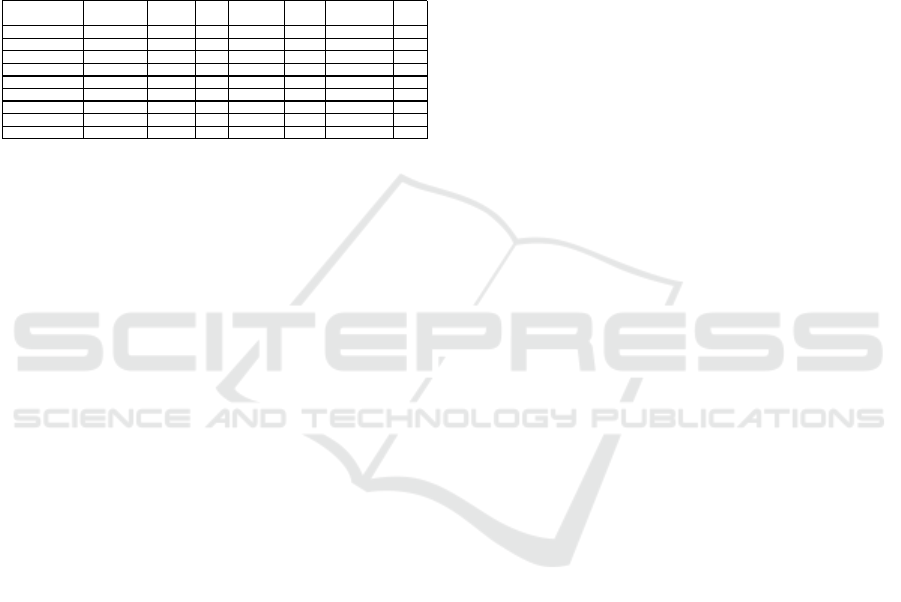
For the realization of the safety concept, we
constructed and built a robotic cell that consists of the
following elements (Figure 1). First, the collaborative
Safety S top
When Triggered
Modi fy
Workplaces
Mobile
System
Indi vidual
Configuration
Flexibility
Allows Maximum
Robot S peed
CE
Mar k
Vo gel e t al.
no yes no no low yes no
Kulic & Croft
no yes no no high no no
Anto nelli et al.
no yes no yes low yes no
Amin et al.
no no no yes low no no
KUKA Sys tems
yes yes no yes very low no yes
Glastechnik Hofmann
yes yes no yes very low yes yes
Rexrot h
yes no yes no high no yes
PILZ
yes yes no yes very low yes yes
Portable Safety System
no no yes no very high yes yes
Portable Safety System using Radar for Flexible Human-Robot-Collaboration in a Real Semi-automated Production Line
69
robot (UR5e) including the teach-panel and the robot
controller, which are mounted on a mobile platform.
This platform can be moved to different workplaces
manually via guide rolls. Second, a framework was
constructed, on which the external sensor system, a
signal tower as well as some pushbuttons and
switches are installed. Third, a control cabinet, which
involves the safe programmable logic controller
(PLC), safe digital I/O modules, the power-supply
unit for 24 VDC and the controller of the radar
sensors.
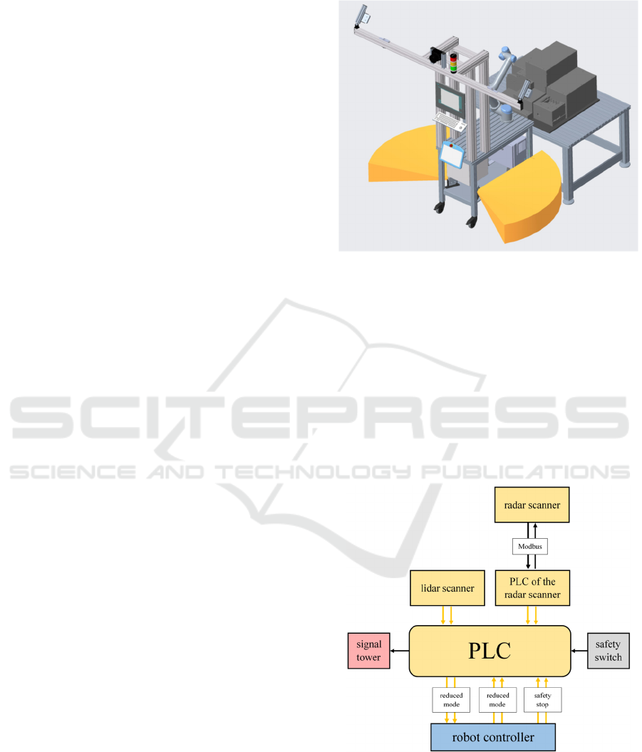
Figure 1: Flexible and mobile robotic cell.
For the communication between the robot cell and
an industrial workplace in a real scenario, a specific
and standardized plug system is used. This plug
contains of the power supply, compressed-air supply
as well as digital I/Os for the controlling of the motion
sequence of the robot. A toggle fastener realizes the
firm connection towards the workplace. The plug and
the toggle fastener make the mobile robotic cell
applicable to different workstations in a real industrial
environment.
4 EXTERNAL SENSOR SYSTEM
The sensor system for the mobile robotic cell consists
of one safe Lidar Laser scanner from SICK, the
S3000 Standard and four safe radar scanner from
Inxpect, the LBK system. A PLC is used to unite the
sensor data. The entire sensor system and all the
described components are configured with two
channels to conform the international standards. For
each of the sensors specific safety distances, which
are defined as the distance from the beginning of the
supervised area by the sensor to the working area of
the robot, have to be calculated.
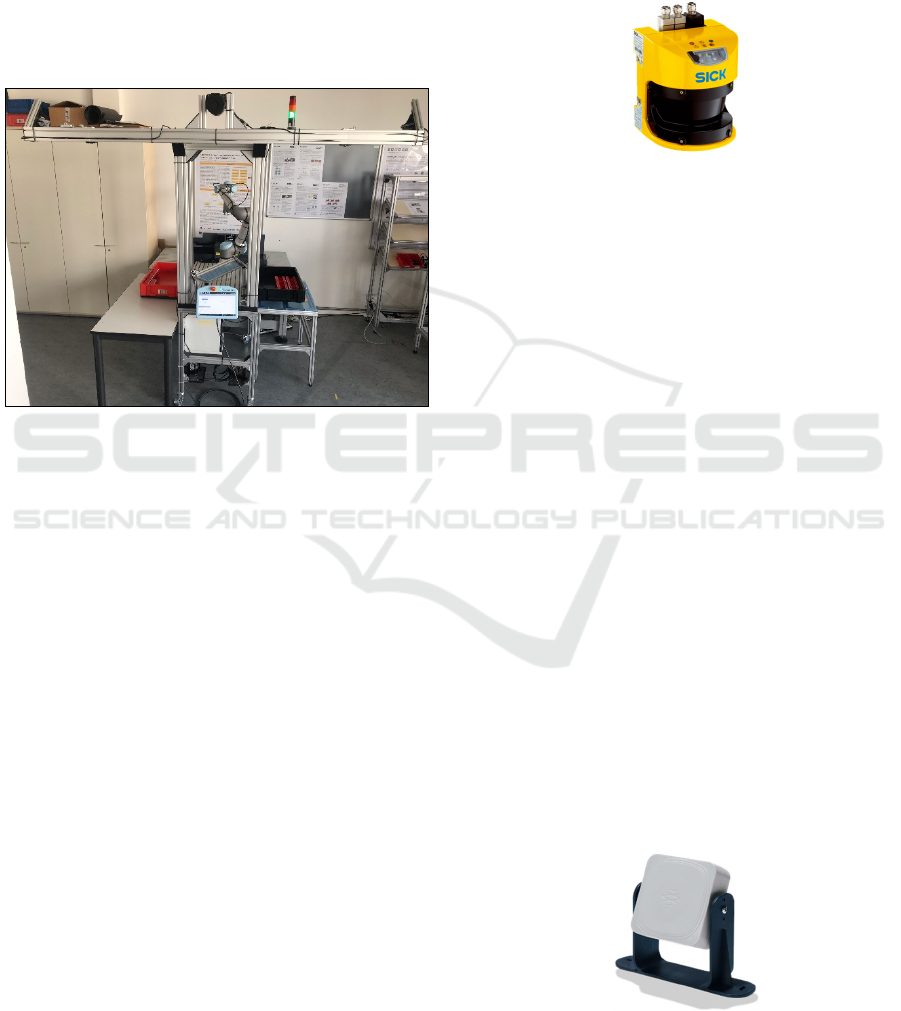
4.1 Safe Lidar Laser Scanner with
Hand Detection
To supervise the access of a human to the front of the
robotic cell, the safe laser scanner is used (Figure 2).
The sensor is working with the method light detection
and ranging (Lidar).
Figure 2: Laser scanner to the front.
By measuring the time between sending and receiving
of laser impulses, the distance can be calculated or
respectively the presence of a human. According to
the international standard DIN ISO13855 (DIN
Deutsches Institut für Normung, 2010) the minimum
safety distance S
min, Laser
to the front side, can be
calculated by (1). The sensor is configured for hand
detection which means that the sensor detection level
d = 40 mm. This value represents the distance
between two laser beams that are emitted by the
sensor. The stopping time T is composed of the
stopping time of the PLC, the laser scanner and the
UR5e Cobot. The approach speed K is a constant
value and is set to 1.600 mm/s according to the
standard, which results with (1) in a minimum safety
distance of S
min,Laser
= 640 mm.
𝑆
,
𝐾∙𝑇8∙
𝑑14
(1)
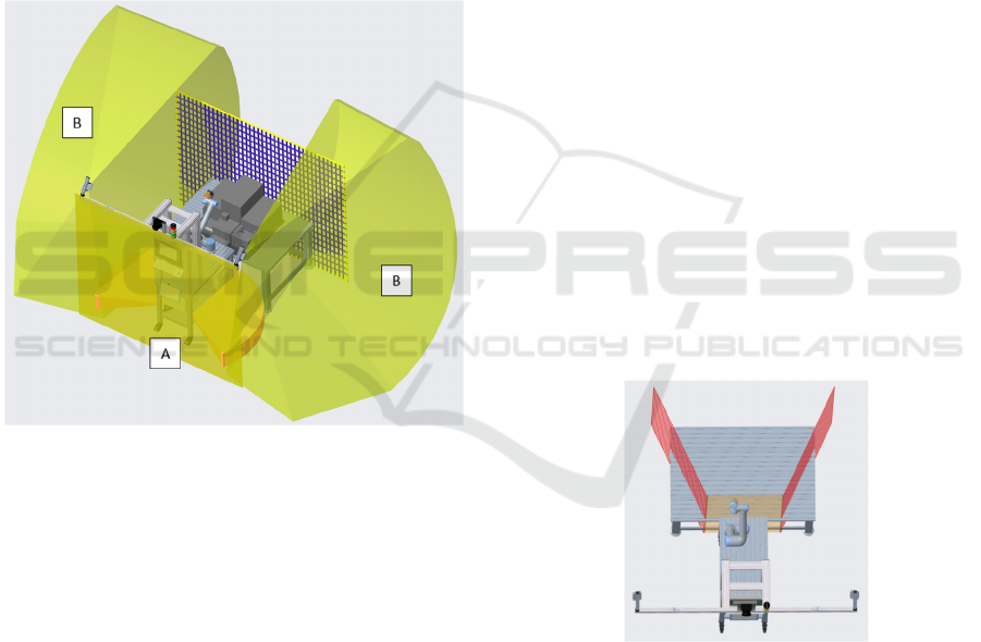
The supervised area by the laser scanner is configured
rectangular. Figure 6 shows the supervised area (A).
4.2 Safe Radar Scanner with Person
Detection
The safe radar scanner are used to detect the access of
a human to both sides of the robotic system (Figure
3).
Figure 3: Radar sensor for the detection to the sides.
ROBOVIS 2021 - 2nd International Conference on Robotics, Computer Vision and Intelligent Systems
70
The LBK system is based on a 24 GHz radar
algorithm that filters out disturbances, e.g. smoke,
dust, splashes or machining waste. This leads to a
reduction of false alarms and thus increases the
productivity. The sensor transmits the radio waves
and identifies motion information by analyzing the
returned signals reflected from both static and moving
objects in the operating area. The sensor only detects
the movement of objects, not the presence of an
object itself, which is the biggest unique feature
compared to a laser scanner. It is also automatically
reconfigured on a new workplace with different
environment, which makes the entire external safety
system portable. The portability is given, when the
robotic cell is added to a new workplace, where the
surrounding always changes. The supervised area of
the radar sensor can be adjusted with two variants
concerning the two axes horizontal and vertical:
• wide protective area: 110° horizontal, 30° vertical
• narrow protective area: 50° horizontal, 15°
vertical
According to DIN 13855 (DIN Deutsches Institut für
Normung, 2010) the minimum safety distance S
min,
Radar
to both sides of the robotic cell can be calculated
by (2):
𝑆
,
𝐾∙𝑇𝐶
(2)
These sensors are configured for person detection,
which implies a sensor detection level d = 70 mm.
The stopping time T is composed of the PLC, the
radar scanner and the UR5e Cobot. With the equal
approach speed K as for the laser scanner and
equation (2) the minimum safety distance S
min, Radar
=
1.242 mm is determined. Figure 6 shows the
supervised are by the radar scanner to both sides (B).
For the automatic restart of the robot with maximum
velocity in normal mode, two more radar sensors are
used to supervise the area that is not covered by the
laser scanner and the radar sensors to both sides. In
case a human worker enters the working area of the
robot the safety system is triggered and the robot is
set to reduced mode. Two additional radar sensors
make sure that no human is inside the robotic cell.
After a timeout of 10 s, the robot is set back to normal
mode. Figure 4 shows the supervised areas for the
automatic restart. To conform the standards, the radar
sensors for the automatic restart have to be mounted
in a specific height over the ground. According to
DIN 13855 (DIN Deutsches Institut für Normung,
2010) the minimum height of the safety field H
min
can
be calculated by (3):
𝐻
15∙
𝑑14
(3)
With a sensor detection level of d = 70 mm and (3),
the minimum height H
min
is calculated with 300 mm.
Figure 4: Supervised area for automatic restart.
4.3 Programmable Logic Control for
Unification
The safe PLC is used for the communication between
the robot controller and the external sensor system.
Figure 5 shows the configuration of the PLC. If one
of the two sensor types (radar or laser) are triggered,
because a worker is entering the supervised area, the
two-channeled digital outputs of the PLC to the robot
controller are switched to FALSE. This transfers the
robot into the reduced mode.
Figure 5: Configuration of the external sensor system by the
PLC.
The robot controller is also communicating with
the PLC, when the robot is either running in the
reduced mode or stands still, because of a safety stop.
Portable Safety System using Radar for Flexible Human-Robot-Collaboration in a Real Semi-automated Production Line
71
Generally, the reduced mode can be triggered by the
external safety system as well as by the internal safety
system through configured protective levels on the
robot. The safety status of the robot is signalized by
the signal tower, so that the worker gets feedback
even if they are not right next to the robot cell. The
safety switch can be used to switch off the external
safety system so that the robot is continuously
running in the reduced mode.
4.4 Entire External Safety System
As shown, the safety distances need to have a
minimum size to detect a human reliably to the front
and to both sides. Figure 6 shows the entire safety
space of the external sensors.
Figure 6: Supervised area of the entire external safety
system.
Behind the workplace a safety fence prevents a
worker from entering the robotic cell. In our research,
we distinguish between two different constitutions of
the space, where the robotic cell is supposed to be set
up. First, the inappropriate space, when there is not
enough space nearby the real industrial workplace for
the supervised area by the external safety system. In
this case, the safety distances can not be maintained
and the sensors are continuously triggered by humans
working next to the robot. Subsequently, the mobile
robotic cell has to run without the supervision by the
external sensors and is set to the reduced mode by the
safety switch. Second, we considered the so called
sufficient space. In this case, there is enough space for
the supervised area of the external sensors, which
means that workers nearby the robot do not
continuously trigger the sensors. Thus, the robot can
run with maximum speed and force and is only
switched to reduced mode when a human is entering
the robotic cell, for example during a change of the
box for the supply and removal of components.
The external safety system is not limited to one
Cobot size. When a bigger robot is used there are not
more sensors needed. When the reactivity of the
bigger robot is different to the current Cobot, either
the angle of the sensors mounted on the mechanical
structure can be adapted or the safety planes can be
moved to hold the safety distance according to the
standard. There is no need to add more sensors.
5 INTERNAL SAFETY SYSTEM:
SAFETY PLANES AT THE
ROBOT
The safety system also uses the internal sensors of the
robot to transfer the robot into the reduced mode and
to limit the movement area of the robot. In our
research, we configured and tested so-called safety
planes at the robot that are presented in the next sub-
chapters.
5.1 Initiate the Reduced Mode
The reduced mode is initiated, when the robot is
crossing predefined safety planes to the front and to
both sides, as it is illustrated in Figure 7.
Figure 7: Safety planes to initiate the reduced mode.
When the robot moves back inside the curtailed area,
it is set back to the normal mode and moves with
maximum speed. Those planes are necessary to
minimize the supervised area by the external safety
system. The angle of the planes to the side is the same
as the angle of the radar sensors that are supervising
the space next to the robotic cell. Thereby, the safety
distance S
min,Radar
can be maintained.
ROBOVIS 2021 - 2nd International Conference on Robotics, Computer Vision and Intelligent Systems
72
5.2 Limiting the Movement Area of the
Robot
In order to integrate the flexible safety system in a real
semi-automated production line, the robot´s
movement nearby the head and face of a human has
to be limited. According to the DIN EN ISO 14738
(DIN Deutsches Institut für Normung, 2009) the
standard height of the shoulders including the heel of
the safety shoes is 134 cm. Therefore, the safety plane
at the robot is configured parallel to the ground at this
height. It is not initiating the reduced mode but is
limiting the movement area of the robot to the top.
Respectively, the Tool-Center-Point (TCP) is not able
to cross it.
6 STANDARDIZED CE-MARK
To fulfill the requirement that no individual safety
assessment has to be performed on a new workplace,
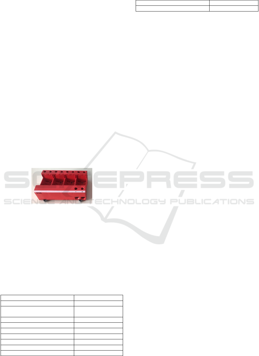
we defined criteria to classify a specific component
series. The biggest (95x145x50mm) and heaviest
(536g) part of the series shows Figure 8.
Figure 8: Component from DEHN SE + Co KG.
The rest of the series consists only of three, two or
one chamber. By the definition of the criteria, also
other parts that looks completely different can be
handled without the performance of an individual
safety assessment. The only precondition is that the
considered application is not accessible from behind
the workplace and the new components correspond to
the specification in Table 2.
Table 2: Classification of a component series for a standard
CE-Label.
Criteria Limit
Basic form Cuboi
d
Sharp forms that are emerging out of
the geometry
Not existing
Size of chambers Max. 32x45mm
Mass Max. 536g
Length Max. 250
Width Max. 250
Heigh
t
Max. 250
Corner radius Min. 0,5mm
Edge radius Min. 0,5mm
Sharp edges/corners Not existing
Surface condition Rz < 1mm
Next to the definition of the criteria, we also
constructed and 3D-printed a safe vacuum gripper
that is able to handle the components of the series. It
consists of two suction devices that can be flexible
removed and added to the housing of the gripper.
Finally, the gripper must not be changed at a new
workplace with new parts, so that the safety
assessment and the assignment of a CE-mark is made
much easier.
To verify our safety system, we also performed an
extensive assessment of risk with the biggest and
heaviest part by using the software SafExpert. The
application we considered was from a project partner
of AdhocMRK. In this case, presorted parts from a
box are picked by the robot and inserted into an
automatic test machine. After the successful high
potential test, the parts are removed and sorted into
another box next to the robotic cell.
Most of the risks could be eliminated by an
inherent safe construction. For the rest of the risks we
performed a force and pressure measurement
according to ISO/TS 15066. By evaluating 40
measurements, we were able to define the safe speed
of the robot by 200 mm/s. That is the speed for the
robotic cell, when it is running in the reduced mode.
7 VALIDATION OF THE SAFETY
SYSTEM
In our research, we also performed the validation of
the flexible safety concept with the radar sensors to
check and confirm the functionality of the system as
following:
• Verification of speed regulation and sensor
activity
• Cycle time measurements for the safety planes
• Adaptability for different workplaces
First, we evaluated and confirmed the functionality of
the implemented safety concept with the described
safety functions. Therefore, we first verified the
positions and range of the supervised areas by the
external and internal sensors. We were both entering
the robotic cell from several sides and moving the
TCP of the robot from inside in direction to the
supervised areas and the safety planes. We checked
the signal for the reduced mode with the signal tower
and the safe digital outputs for the reduced mode on
the robot controller for several positions.
Portable Safety System using Radar for Flexible Human-Robot-Collaboration in a Real Semi-automated Production Line
73
Second, in order to analyze the influence of the
variation of the safety planes position on the cycle
times, a prototypical application was examined.
When the robot is crossing the planes, it is transferred
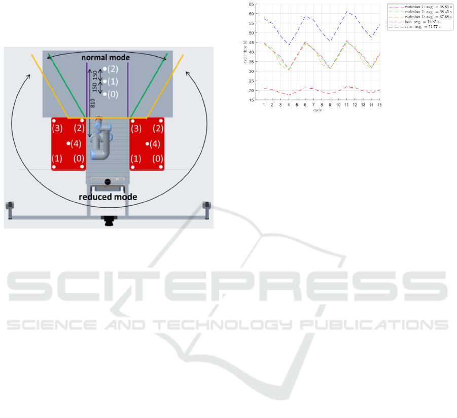
to the reduced mode. Figure 9 shows the experimental
setup for the time measurements:
Figure 9: Experimental setup for the variation of safety
planes position and time measurements.
The robot is moving cyclic from position (0) of
the left box to position (0) on the table, which
characterizes the workplace, to position (0) of the
right box. Thus, the path would be (0, 0, 0). In the
next cycle, the robot starts again from (0) of the left
box, to (0) of the table and to (1) of the right box. So
the entire sequence would be from (0, 0, 0) to (0, 0,
4), continued with (0, 1, 0) to (0, 1, 4) and so on. The
last cycle is from (4, 2, 3) to (4, 2, 4). Finally, the
robot was driving to every position from the left box,
combined with every position on the table and every
position from the right box during one sequence. All
the positions were sent to the robot via a TCP/IP
socket connection between a computer and the robot
controller. The time was measured for each cycle by
a C#-program and saved to a .csv-file for evaluation.
Overall, we recorded three sequences, which contain
of 75 cycles each. Every sequence is representing one
configurations of the safety planes. In summary, we
evaluated 225 cycles. The longest cycle times
expected to be from point (1) of the left box to all the
other positions of the table and the right box, because
it is the longest path of the robot. Thus, this point is
considered for the evaluation. According to that, the
robot performs five cycles crossing each of the three
points on the table (0, 1 and 2), which results in 15
measurements. In normal mode, the robot drives with
a speed of 400 mm/s, which is performed mostly
nearby the table. When the robot is crossing the
planes, it is only moving with 200 mm/s. Figure 10
shows the result of our cycle time measurement:
Figure 10: Evaluation of the cycle time measurements.
Next to the transition from normal to reduced
mode by the different safety plane configurations, we
were also testing the robot continuously running in
the normal (fast) and the reduced mode (slow). Our
experiment shows that the position of the safety
planes has no significant influence on the cycle times
(variation 1-3). The average value differs only by
1.4 s. The speed of the robot is most essential,
respectively the speed in the reduced mode. This has
the biggest influence.
Third, we recorded and compared the time the
radar systems needs to adapt to new workplaces.
When a new object is added to the supervised area of
the sensors, a new workspace is created. In this case,
the sensors have to be initialized and adapted to the
new environment. This is done automatically by the
sensors and can be monitored by the safe two-
channeled digital outputs of the controller. When the
environment changes, the digital outputs stay FALSE
until they are finally initialized and switched to
TRUE. A timer, which has been programmed on the
robot controller, supervises the digital outputs and
determines the time of initialization.
To create new workspaces in the laboratory, four
boxes of different sizes were selected (30x20x150,
40x30x220, 600x400x120, 600x400x320mm) and set
up with varied combinations on a table next to the
robotic cell. The latter is inside the supervised area of
the radar sensors. These boxes are standardized
according to VDA 4500 and are most commonly used
in the automobile industry and for high-automated
production processes. The number and size of the
boxes define the complexity of the combinations. The
higher the number and the bigger the size of the
boxes, the higher the complexity. In our set up, we
distinguish between four grades of complexity: low,
medium, high and very high. Figure 11 illustrates the
results of the initialization measurements for different
workplaces:
ROBOVIS 2021 - 2nd International Conference on Robotics, Computer Vision and Intelligent Systems
74
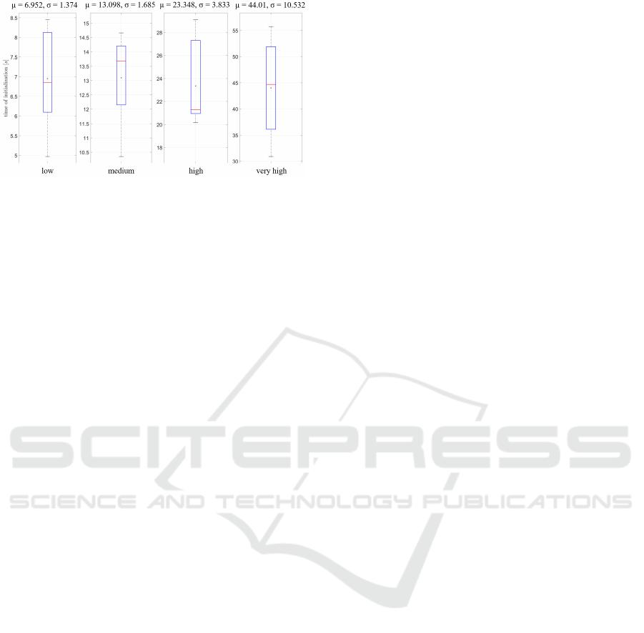
Figure 11: Time of initialization with different
complexities.
The median, which is represented by the red
horizontal lines, show that the smaller the change in
the scenario compared to the previous one, the faster
is the time of initialization. The interquartile range
(IQR) differs from 2 s (low), to 2.2 s (medium), 6.3 s
(high) and 15 s (very high). Therefore, the higher the
complexity the higher is the variance for the time of
initialization. Nevertheless, the measurements show
that the highest recorded time was 55 s. When a
worker is manually configuring the sensors at a new
workplace, e.g. a laser scanner to both sides instead
of the radar sensors, the time would be considerably
longer.
8 CONCLUSION
In summary, we presented a safety system that can be
flexibly used for different real industrial applications.
Because of the specific feature of the radar sensors,
no individual configuration is necessary, when the
mobile robotic cell is set up on a new workplace.
Furthermore, all the sensors to supervise the
workspace of the robot are mounted on the mobile
platform. This makes it easy, flexible and fast to be
integrated in an existing production line, because no
workplace has to be adapted. We also presented a first
approach to achieve a standardized CE-mark for a
component series. The laser scanner at the front also
reduces the supervised space in front of the robotic
cell. The advantage is that workers walking by via a
footway do not trigger the safety sensors. The entire
safety system has a high flexibility and mobility,
because it is usable on different workplaces with
different surrounding without an individual safety
consideration and without the adaption of configured
safety planes and safety areas of the radar and laser
sensors. The presented solution is usable in a real
industrial surrounding for the entire e-series of
Universal Robot, but is not limited to those Cobots.
Most of the Cobots have the possibility to program
safety planes that transfer the robot to the reduced
mode. Nevertheless, to improve the efficiency and the
usage of the presented safety system, more testing
with different Cobots is necessary.
For further research, the sensitivity level of the
radar sensors (normal, high, very high) in relation to
the speed and acceleration of the robot is supposed to
be analyzed. When the robot stops too quick or
accelerates too fast, the sensors mounted on the
framework are triggered, because of small vibrations
on the mobile cell. To avoid the undesired triggering
of the radar sensors and to reduce the cycle times
more research is necessary.
ACKNOWLEDGEMENTS
This work was conducted within the research project
AdhocMRK funded by the Kompetenzzentrum
Mittelstand GmbH (KME). We are thankful for the
support and funding from the KME.
REFERENCES
Amin, F., Rezayati, M., Venn, H., & Karimpour, H. (2020).
A Mixed-Perception Approach for Safe Human-Robot
Collaboration in Industrial Automation. In Sensors (S.
1-20). MDPI.
Antonelli, D., Astanin, S., Caporaletti, G., & Donati, F.
(2014). FREE: Flexible and Safe Interactive Human-
Robot Environment for Small Batch Exacting
Applications. In Springer Tracts in Advanced Robotics
(S. 47-62). Springer.
Berg, J., Richter, C., & Reinhart, G. (2018). Integration of
Safety elements into task-oriented programming system
for human-robot-collaboration. In International
Symposium on Robotics (ISR) (S. 281-284). Frankfurt
am Main, Germany: VDE.
DIN Deutsches Institut für Normung. (2009). Safety of
machinery - Anthropometric requirements for the
design of workstations at machinery (ISO 14738:
2009). Berlin: Beuth Verlag GmbH.
DIN Deutsches Institut für Normung. (2010). Safety of
machinery – Positioning of safeguards with respect to
the approach speeds of parts of the human body (ISO
13855:2010). Berlin: Beuth Verlag GmbH.
DIN Deutsches Institut für Normung. (2011). Robots and
robotic devices - Safety requirements for industrial
robots - Part 2: Robot systems and integration (ISO
10218-2:2011). Berlin: Beuth Verlag GmbH.
DIN Deutsches Institut für Normung. (2011). Robots and
robotic devices- Safety requirements for industrial
robots - Part 1: Robots (ISO 10218-1:2011). Berlin:
Beuth Verlag GmbH.
Portable Safety System using Radar for Flexible Human-Robot-Collaboration in a Real Semi-automated Production Line
75

DIN Deutsches Institut für Normung. (2016). Robots and
robotic devices - Collaborative robots (ISO/TS
15066:2016). Berlin: Beuth Verlag GmbH.
Dohi, M., Okada, K., Maeda, I., Fujitani, S., & Fujita, T.
(2018). Proposal of Collaboration Safety in a
Coexistence Environment of Human and Robots. In
IEEE International Conference on Robotics and
Automation (ICRA) (S. 1924-1930). Brisbane,
Australia: IEEE.
Glastechnik Hofmann GmbH. (2017). Chromos Industrial.
Von https://cobots.ch/en/casestudies/hofmann-
glastechnik-handling-of-highly-sensitive-glass-tubes/
abgerufen
Halme, R.-J., Lanz, M., Kämäräinen, J., Pieters, R.,
Latokartano, J., & Hietanen, A. (2018). Review of
vision-based safety systems for human-robot
collaboration. In Proceedings of the 51st CIRP
Conference on Manufacturing Systems (S. 111-116).
Elsevier.
Hoskins, G., Padayachee, J., & Bright, G. (2019). Human-
Robot Interaction: The Safety Challenge (An inegrated
frame work for human safety). In Proceedings of the
South Africa Regional Conference
(SAUPEC/RobMech/PRASA Conference) (S. 74-79).
Bloemfontein, South Africa: IEEE.
KUKA Systems GmbH. (2018). HRC in the production of
the BMW Group. (KUKA) Von https://www.
kuka.com/en-de/industries/solutions-database/2017/06
/solution-systems-bmw-dingolfing abgerufen
Kulic, D., & Croft, E. (2005). Real-Time Safety for Human-
Robot Ineraction. In 12th International Conference on
Advanced Robotics (S. 719-724). Seattle, USA: IEEE.
Lasota, P., Fong, T., & Shah, J. (2020). A survey of
methods for safe human-robot interaction. In
Christensen, H., Siegwart, R. (Eds.), Foundations and
Trends in Robotics (S. 261-349). Boston - Delft: Now
publishers Inc.
Matthias, B., Kock, S., Jerregard, H., Kallman, M.,
Lundberg, I., & Mellander, R. (2011). Safety of
collaborative industrial robots: Certification
possibilities for a collaborative assembly robot concept.
In IEEE International Symposium on Assembly and
Manufacturing (ISAM). Tampere, Finland: IEEE.
Pang, G., Yang, G., Heng, W., Ye, Z., Huang, X., Yang, H.,
& Pang, Z. (2021). CoboSkin: Soft Robot Skin With
Variable Stiffness for Safer Human–Robot
Collaboration. In IEEE Transactions on Industrial
Electronics (S. 3303-3314). IEEE.
PILZ. (2014). Safe camera system SafetyEYE. Von
https://www.pilz.com/en-
INT/eshop/00106002207042/SafetyEYE-Safe-camera-
system abgerufen
Rexroth. (2014). Intelligent systems for the flexible factory.
Von
https://apps.boschrexroth.com/microsites/apas/index.ht
ml abgerufen
Salmi, T., Väätäinen, O., Malm, T., Montonen, J., &
Marstio, I. (2013). Meeting New Challenges and
Possibilities with Modern Robot Safety Technologies.
In 5th International Conference on Changeable, Agile,
Reconfigurable and Virtual Production (S. 183-188).
Munich, Germany: Springer.
Vogel, C., Walter, C., & Elkmann, N. (2013). A projection-
based sensor system for safe physical human-robot
collaboration. In Proceedings of the IEEE/RSJ
International Conference on Intelligent Robots ans
Systems (IROS) (S. 5359-5364). Tokyo, Japan: IEEE.
Vogel, C., Walter, C., & Elkmann, N. (2017). Safeguarding
and Supporting Future Human-robot Cooperative
Manufacturing Processes by a Projection- and Camera-
based Technology. In Proceedings of the 27th
International Conference on Flexible Automation and
Intelligent Manufacturing (FAIM) (S. 39-46). Modena,
Italy: Elsevier.
Zlatanski, M., Sommer, P., Zurfluh, F., & Madonna, G.
(2018). Radar Sensor for Fenceless Machine Guarding
and Collaborative Robotics. In IEEE International
Conference on Intelligence and Safety for Robotics
(ISR) (S. 19-25). Shenyang, China: IEEE.
ROBOVIS 2021 - 2nd International Conference on Robotics, Computer Vision and Intelligent Systems
76
