
Dynamics of a Four Wheeled Wall Climbing Robot
Anokhee Chokshi
a
and Jaina Mehta
b
School of Engineering and Applied Science, Ahmedabad University, Ahmedabad, Gujarat, India
Keywords:
Wall Climbing Robot, Dynamic Modeling, Wheel Slip, Wheel Dynamics, Vertical Contact Forces.
Abstract:
In this paper, a mathematical model of a four wheeled independently driven Wall Climbing Robot (WCR) is
developed. The consideration of only the kinematic model for a WCR may reduce its performance during sud-
den changes in acceleration and turning. To address this issue, a dynamic model that includes the wall/wheel
interactions i.e., lateral and longitudinal frictional forces, is proposed. The effect of wheel slip is considered
for a more realistic dynamic model. The models that are typically developed for the vertical contact forces, an
important parameter affecting the frictional forces, assume equal weight distribution on the wheels. However,
to accommodate the load shift due to the variation in acceleration along with the distribution of adhesion force,
lateral and longitudinal acceleration components are also taken into account. The major components of this
WCR model consist of the wheel dynamics, the wall/wheel interactions, the kinematics and the dynamics.
Simulations are performed to demonstrate and verify the model. The suggested model in the future can be
applied in the development of control algorithms for wheeled WCRs.
1 INTRODUCTION
Wall Climbing Robots (WCR)s have been extensively
studied in recent years for their potential applications
in regular maintenance and inspection of urban struc-
tures that may be arduous and dangerous to work on
due to their intricate construction. The use of these
robots ensures safety for humans to work in hostile
environments and ease in access to these structures.
Locomotion is the pivotal issue for the design of
any mobile robot. In the case of a WCR, there exist
different locomotion mechanisms: bio-inspired type
(Chen et al., 2015), (Aksak et al., 2008), legged type
(Palmer et al., 2009), (Zhan et al., 2017) and wheeled
type (Faisal and Chisty, 2018), (Jun Li et al., 2009). In
comparisonto vehicles that travelon the ground, these
robots require a potent adhesive mechanism to create
a firm grip on the wall. Generally, one of the three
types of adhesion mechanisms: suction cups (Shujah
et al., 2019), (Sano et al., 2017), magnetic adsorp-
tion (Gong et al., 2010), (Hu et al., 2017) or thrust
force(Inoue et al., 2018), (Alkalla et al., 2015) is used
to solve the purpose.
In this paper, a mathematical model for a WCR
which uses wheels for locomotion and thrust force for
adhesion is developed. The selection of these mecha-
a
https://orcid.org/0000-0003-3859-6543
b
https://orcid.org/0000-0003-1972-401X
nisms is based on the fact that the thrust force required
for adhesion, which is generated using a propeller or
impeller, allows the robot to travel over surfaces with
different gradients and the wheels enable the WCRs
to attain higher velocities.
Several models for the dynamics of ground ve-
hicles exist in the literature. The model developed
in (Sebsadji et al., 2008) is for the case of a vehi-
cle with two steering wheels traveling on a road with
a non-zero slope angle. (Liao et al., 2019) have de-
veloped a mathematical model for a four wheel inde-
pendently driven skid steer mobile robot. A model
for wheel dynamics has also been presented here.
(Kiencke and Nielsen, 2000) and (Wang, 2013) have
introduced models for normal forces in addition to the
vehicle lateral and longitudinal dynamic model for a
four wheeled vehicle traveling on the ground. The
theories of such models can be further extended to
formulate models that establish the case of a WCR.
A considerable amount of research has been car-
ried out for developing mathematical models for
WCRs using different approaches. Most researchers
ignore robot dynamics and only take kinematic
models into account for the purpose of simplicity
(Minzhao et al., 2015), (Gao and Kikuchi, 2004).
(Panchal et al., 2014) have considered the forces act-
ing on the WCR when it is traveling on a vertical wall.
But for the vertical contact forces, equal weight dis-
530
Chokshi, A. and Mehta, J.
Dynamics of a Four Wheeled Wall Climbing Robot.
DOI: 10.5220/0010615605300536
In Proceedings of the 18th International Conference on Informatics in Control, Automation and Robotics (ICINCO 2021), pages 530-536
ISBN: 978-989-758-522-7
Copyright
c
2021 by SCITEPRESS – Science and Technology Publications, Lda. All rights reserved
tribution of the robot on the four wheels is assumed.
(Xu and Liu, 2017) have presented a simplified model
for the dynamics of a four wheeled differential drive
WCR. However, the moment of inertia and the rolling
friction between the wheels and the wall are ignored
here. Certain other complex and complicated models,
which account for obstacle avoidance have also been
developed in (Xu et al., 2015) and (Ioi, 2012).
The main theme of the paper lies in the de-
velopment of a dynamic model that includes the
wall/wheel interactions i.e lateral and longitudinal
frictional forces acting on a WCR. The major pa-
rameters affecting these frictional forces are vertical
contact forces and wheel slip. In contrast to ground
robots where the vertical contact forces are depen-
dent on the weight distribution; in the case of a WCR,
they depend on the adhesion force. As discussed in
(Kiencke and Nielsen, 2000) and (Wang, 2013), in
this paper, vertical contact forces are derived based
on the load shift due to the variation in acceleration
and the distribution of adhesion force on each wheel.
The WCR dynamics proposed in this paper also ac-
count for the effect due to wheel slip, based on the
models of rolling friction between the wheels and the
ground for a mobile robot (Liao et al., 2019), (Cerkala
and Jadlovska, 2014). The main contribution of this
paper lies in the fact that it provides a realistic model
for four wheeled WCR. The proposed model can be
used for implementing control algorithms to enhance
the performance of the WCRs in the future.
The rest of the paper is organized as follows. Sec-
tion 2 presents the main contribution of the proposed
mathematical model. Section 3 validates the mathe-
matical model through simulations. Section 4 draws
the conclusion of the proposed mathematical model
and includes future direction.
2 SYSTEM MODELING
The design of a WCR consists of two parts: locomo-
tion and adhesion. In this paper, the WCR has four
wheels for locomotion, which can be driven indepen-
dently to maneuver the robot on a wall that is perpen-
dicular to the ground. For adhesion, it is considered
that the robot uses thrust force. This thrust force can
be generated by the blades of a propeller or impeller,
which are made to rotate such that air is thrown out
from the upper side of the robot. This creates a pres-
sure difference between the two sides of the robot and
increases the friction force between the wheels of the
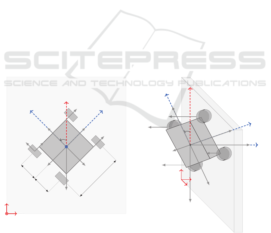
robot and the wall. Figure 1 represents the forces act-
ing on a WCR when it is placed on the wall.
In this paper, it is assumed that all the wheels are
in contact with the wall at all times. This implies that
there is no roll or pitch motion of the robot. It is also
+Y
+X
+Z
+
Y
+
X
+
Y
+
X
+x
+y
+X
l
r
l
f
b
mg
mg
y
mg
x
F
x
1
F
y
1
ma
y
ma
x
m
∗
1,2
a
y
m
∗
3
,
4
a
y
ψ
+z
1 2
3
4
F
N3
1
2
3
4
+x
+z
+y
+X
ψ
ma
y
mg
y
mg
x
ma
x
mg
F
a
F
N1
F
N2
F
N4
o(
x, y)
+Z
+X
+Y
(a) Front view of the WCR. (b) Isometric view of the WCR.
Figure 1: Representation of the forces acting on the WCR when it is at an arbitrary angle ψ.
Dynamics of a Four Wheeled Wall Climbing Robot
531

Wheel
Dynamics
Dynamics
Kinematics
Vertical
contact
forces
Angular velocity
of wheels
Lateral
frictional forces
Lateral and
Longitudinal
acceleration
Normal
forces
Adhesion
force
Input
torque
Lateral and
Longitudinal velocity
Angular
velocity
Position and
Orientation
Figure 2: Mathematical model of the WCR.
assumed that the centre of mass is the same as the
geometrical centre of the robot. A thrust force F
a
,
which creates enough adhesion for the robot to stick
to the wall, acts perpendicular to the wall.
As per Figure 1, let XYZ be the global co-ordinate
system and xyz be the co-ordinate system attached to
the robot. (X,Y) and ψ are the position and orientation
of the robot with respect to the global co-ordinate sys-
tem. l
r
and l
f
represent the distance between the cen-
tre of mass and the centres of the rear wheel and the
front wheel respectively, b is the distance between the
left and right wheels and H is the distance between
the centre of mass and the wall. m is the mass of the
robot. The gravitational acceleration acts in the −X
direction and has two components in x and y direc-
tion in the local co-ordinate frame that is attached to
the robot, denoted by g
x
= g cosψ and g
y
= g sinψ.
The mathematical model that is proposed in this
paper is illustrated by the block diagram in Figure 2.
It consists of four parts - the dynamics of the wheel,
which give a relation between the input torque and an-
gular velocity of each wheel while taking the damping
effect into account; the vertical contact forces on each
wheel; the WCR dynamics, which include the effect
of wheel slip; and the kinematics of the WCR, which
give the position and orientation of the robot w.r.t. the
global co-ordinates. The model of each sub-part is
discussed in detail in the subsequent sub-sections.
2.1 Vertical Contact Forces
When the mobile robot travels on the ground, the total
vertical force is caused by the force due to the earth’s
gravitational acceleration. Whereas, when the robot
is traveling on a wall, which is perpendicular to the
ground, the total vertical force is caused due to the
adhesion force. Apart from adhesion force, other fac-
tors like the longitudinal and lateral acceleration of
the robot chassis and the geometry of the robot are
considered in determining the normal force on each
wheel as discussed in (Kiencke and Nielsen, 2000),
(Wang, 2013). However, certain other factors like the
wall surface geometry and air resistance are not con-
sidered and some reasonable simplifications are made
for reducing the complexity.
The contact forces alter as the vehicle acceleration
changes. Due to inertia, the acceleration of the chas-
sis (a
xc
, a
yc
) is in the opposite direction of the longi-
tudinal and lateral accelerations (a
x
, a
y
) i.e. when the
robot accelerates in the forward direction, the chas-
sis accelerates in the backward direction because the
wheel load shifts to the rear axle. Hence, a
xc
= −a
x
and a
yc
= −a
y
.
Since it is assumed that there is no pitch, the force
due to acceleration in the +x-direction causes a torque
which reduces the load on the front axle and increases
the load on the rear axle. Here, axle is an imaginary
line that connects the centres of the front wheels or
rear wheels. As seen in Figure 1 (b), the normal force
acting on the front wheels (F
N1
,F
N2
) is given by cal-
culating the total moment on the rear axle.
(F
N1
+ F
N2
)(l
r
+ l
f
) = −ma
xc
H − mg
x
H + F
a
l
r
(1)
The front and the rear axle are assumed to be
decoupled. As seen in Figure 1, m
∗
1,2
and m
∗
3,4
de-
note the virtual mass present at the front and rear
axle respectively. They can be expressed as m
∗
1,2
=
(F
N1
+ F
N2
)/a
z
and m
∗
3,4
= (F
N3
+ F
N4
)/a
z
, where a
z
is the acceleration in the direction perpendicularto the
wall. Based on Equation (1), the virtual mass at the
front axle can be rewritten as:
m
∗
1,2
= −
m
2
a
xc
H
F
a
(l
r
+ l
f
)
−
m
2
gcosψH
F
a
(l
r
+ l
f
)
+
m(l
r
)
(l
r
+ l
f
)
(2)
Since it is also assumed that there is no roll, as
shown in Figure 1, considering the torque balance at
ICINCO 2021 - 18th International Conference on Informatics in Control, Automation and Robotics
532

the front right wheel, the normal force acting on the
front left wheel is calculated as:
F
N1
(b) = m
∗
1,2
a
z
(b/2) + m
∗
1,2
a
yc
H + m
∗
1,2
g
y
H (3)
When the longitudinal and lateral coupling is not
taken into account, the equations of the normal forces
acting on each wheel can be expressed as:
F
N1
= −
m(a
xc
+ gcosψ) H
2(l
r
+ l
f
)
+
F
a
(l
r
)
2(l
r
+ l
f
)
+
m(l
r
)(a
yc
+ gsinψ) H
(b)(l
r
+ l
f
)
F
N2
= −
m(a
xc
+ gcosψ) H
2(l
r
+ l
f
)
+
F
a
(l
r
)
2(l
r
+ l
f
)
−
m(l
r
)(a
yc
+ gsinψ) H
(b)(l
r
+ l
f
)
F
N3
=
m(a
xc
+ gcosψ) H
2(l
r
+ l
f
)
+
F
a
(l
f
)
2(l
r
+ l
f
)
+
m(l
f
)(a
yc
+ gsinψ) H
(b)(l
r
+ l
f
)
F
N4
=
m(a
xc
+ gcosψ) H
2(l
r
+ l
f
)
+
F
a
(l
f
)
2(l
r
+ l
f
)
−
m(l
f
)(a
yc
+ gsinψ) H
(b)(l
r
+ l
f
)
(4)
The above equations consider the effect of adhe-
sion force; and the longitudinal and lateral acceler-
ations on the vertical contact force acting on each
wheel.
2.2 Kinematic Model of the WCR
Based on the orientation of the co-ordinate systems as
shown in Figure 1, the kinematic model of the WCR
is expressed as:
˙
X = v
x
cos(ψ) + v
y
sin(ψ)
˙
Y = −v
x
sin(ψ) + v
y
cos(ψ)
˙
ψ = ω (5)
(v
x
, v
y
) denote the velocity of the robot in the x and
y directions respectively and ω is the angular velocity
of the robot.
2.3 Dynamic Model of the WCR
The dynamic model of the WCR considering slip
compensation is expressed as:
m ˙v
x
=
4
∑
i=1
F
xi
+ mv
y
ω− mg
x
m ˙v
y
=
4
∑
i=1
F
yi
− mv
x
ω− mg
y
¨
ψ =
1
I
z
4
∑
i=1
M
zi
(6)
F
xi
and F
yi
are the longitudinal and lateral fric-
tional forces. The moment around z-axis is given by
M
zi
and the moment of inertia around z-axis is I
z
.
Generally, in the case of ground robots, the fric-
tion forces acting against the mobile robot are ig-
nored with the assumption of pure rolling. However,
it becomes necessary to include them in the dynamic
model of the WCR since there will be no adhesion in
their absence. A simplified model for friction forces
due to ground and wheel interactions based on (Liao
et al., 2019) is used.
F
xi
= F
Ni
µ
r
S
f
(s
i
)
s
xi
s
i
F
yi
= F
Ni
µ
s
S
f
(s
i
)
s
yi
s
i
4
∑
i=1
M
zi
= l
f
(F
y1
+ F
y2
) +
b
2
(−F
x1
+ F
x2
−F
x3
+ F
x4
) − l
r
(F
y3
+ F
y4
) (7)
F
Ni
are the normal forces which are calculated in
Section 2.1. ; µ
r
and µ
s
are the rolling and sliding
co-efficients of friction; s
xi
and s
yi
represent the lon-
gitudinal and lateral slip for each wheel and can be
calculated as:
s
x1
= rω
r1
− v
x
+ (b/2)ω, s
y1
= v
y
+ l
f
ω
s
x2
= rω
r2
− v
x
− (b/2)ω, s
y2
= v
y
+ l
f
ω
s
x3
= rω
r3
− v
x
+ (b/2)ω, s
y3
= v
y
− l
r
ω
s
x4
= rω
r4
− v
x
− (b/2)ω, s
y4
= v
y
− l
r
ω (8)
ω
ri
is the angular velocity of each wheel. This
is obtained using the input torque on each wheel de-
scribed in the following sub-section. From Equa-
tion (8), s
i
=
p
s
xi
2
+ s
yi
2
and the dynamic feature of
the friction force can be approximated as: S
f
(s
i
) =
2
π
atan(90s
i
).
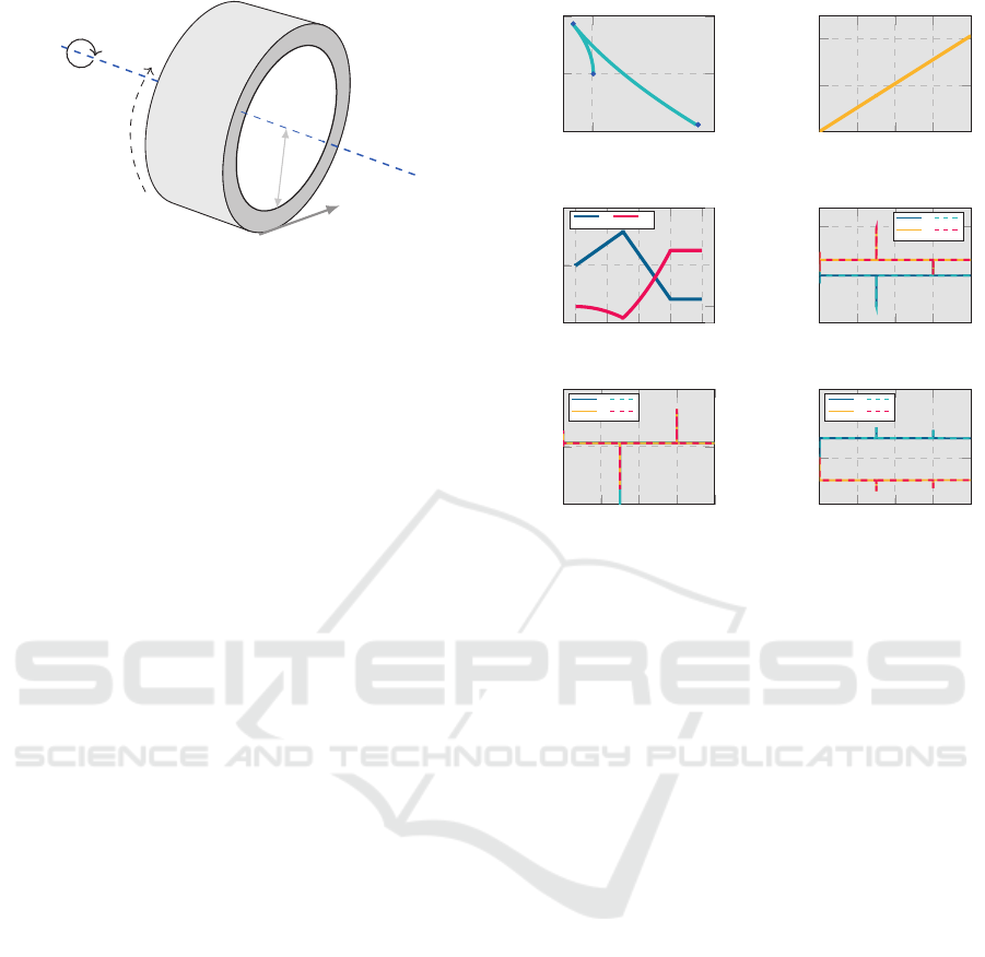
2.4 Wheel Dynamics
The rotational dynamics of each wheel are derived
from Figure 3.
J
ri
˙
ω
ri
+ c
ri
ω
ri
= u
ri
− rF
xi
(9)
Dynamics of a Four Wheeled Wall Climbing Robot
533
r
F
xi
ω
ri
u
ri
Figure 3: Wheel rotational motion.
J
ri
represents the moment of inertia, c
ri
is the
damping co-efficient, ω
ri
is the angular velocity, u
ri
denotes the input torque and r is the radius of the
wheel.
3 SIMULATION RESULTS
The realistic dynamic model that includes wall and
wheel interactions and wheel slip for the WCR is sim-
ulated in the Simulink environment. The response of
the proposed model is generated with different robot
orientations and by providing different input torques
to the robot wheels. The solution of the model equa-
tions is obtained by ode45 solver, with the error tol-
erance set to 10
−4
and the simulation time set to 20s.
The lateral velocity and its derivatives are bounded
based on the robot geometry and physical constraints.
For the purpose of the simulation, it is consid-
ered that b = 610 × 10
−3
m, l
f
= 175.01 × 10
−3
m,
l
r
= 175.01× 10
−3
m, H = 33.38× 10
−3
m, r = 35×
10
−3
m, c
ri
= 0.1N/m, J
ωi
= 3.68× 10
−5
kgm
2
, µ
r
=
0.5, µ
s
= 0.9, m = 1.75kg, I
z
= 11.74 × 10
−2
kgm
2
and F
a
= 51.5N.
As illustrated in Figure 4, for Case 1, when the
WCR is initially at ψ = 0, a constant and identical in-
put torque is given to all the four wheels for the first
time interval. This results in the upward movement
of the WCR i.e. movement in the +X direction. Due
to the consideration of lateral frictional forces, minor
changes in the orientation of the robot ψ and move-
ment in the Y-axis are observed. In the second time
interval, the input torque of the same magnitude but
opposite in direction is given to all four wheels. This
produces results similar to the first interval. However,
the movement of the robot is in reverse direction i.e.
in the -X direction. It is important to note that the
same magnitude of torque in the reverse direction in
this case produces a greater amount of change in the
position of the robot. This is caused due to the grav-
itational acceleration acting in the -X direction. No
torque is given to the wheels in the third interval. As
−2 · 10
−2
×10
−3
−1
0
1
t = 0 s
7.5s
15s
20s
Y (m)
X (m)
0
5
10
15
20
0
1
2.01
×10
−3
t (s)
ψ (rad)
0
5
10
15
20
−1.5
0
1.5
t (s)
X (m)
−0.5
0
3
×10
−3
Y (m)
X Y
0
5
10
15
20
20
25
30
t (s)
N
i
(N)
N
1
N
2
N
3
N
4
0
5
10
15
20
−0.1
0
0.1
t (s)
s
xi
(m/s)
s
x1
s
x2
s
x3
s
x4
0
5
10
15
20
−4
0
6
×10
−5
t (s)
s
yi
(m/s)
s
y1
s
y2
s
y3
s
y4
Figure 4: (Case 1) : (X
0
,Y
0
) = (0,0); ψ
0
= 0; u
ri
= 0.5 Nm
(0 ≤ t ≤ 7.5); u
ri
= -0.5 Nm (7.5 < t ≤ 15) and u
ri
= 0 Nm
(15 < t ≤ 20).
the robot is in motion, it takes a finite time for it to
preserve its final position in X and Y directions.
It can be observed from the wheel slip graphs
in Figure 4 that when a constant and identical input
torque is given to all four wheels, the wheel slip is
close to zero. At t = 7.5s and t = 15s, i.e. at the
points when the torque value changes, there is a sud-
den change in wheel slip.
The longitudinal and lateral accelerations are zero
when the input torque is constant. It can be observed
from Figure 4 that the normal forces remain constant
for each time interval as the only other factors affect-
ing them are the gravitational acceleration and ad-
hesion force, which are constant. A sudden change
is seen only at the points when the input torque is
changed.
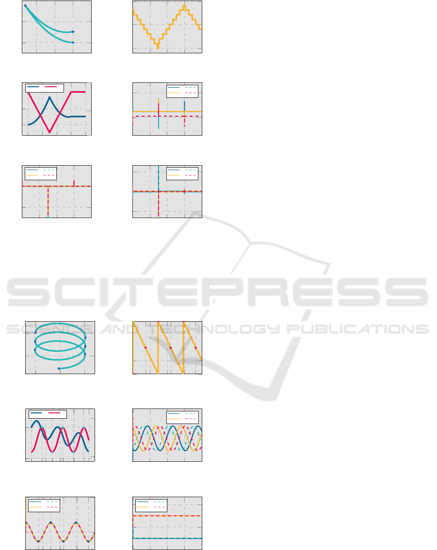
Figure 5 illustrates the results of Case 2, where the
input torque remains the same as Case 1, butthe initial
orientation of the robot is changed to ψ = π/2. This
means that the robot would replicate the movement of
the robot as in Case 1, but in the Y-axis instead. How-
ever, due to the absence of gravitational acceleration
in the direction of movement of the robot, when the
robot is at an angle ψ = π/2, the same magnitude of
torque in the reverse direction in the second time in-
terval would result in the same change in position as
seen in the first time interval. In this case, the effect
of lateral frictional forces is seen in the X-direction.
ICINCO 2021 - 18th International Conference on Informatics in Control, Automation and Robotics
534
−1
−0.5
0
0
3
×10
−4
t = 0s
7.5s
15s
20s
Y (m)
X (m)
0
5
10
15
20
1.57
1.571
t (s)
ψ (rad)
0
5
10
15
20
0
3
×10
−4
t (s)
X (m)
−1.4
0.3
Y (m)
X Y
0
5
10
15
20
25
30
t (s)
N
i
(N)
N
1
N
2
N
3
N
4
0
5
10
15
20
−0.1
0
0.1
t (s)
s
xi
(m/s)
s
x1
s
x2
s
x3
s
x4
0
5
10
15
20
−1.5
0
1.5
×10
−3
t (s)
s
yi
(m/s)
s
y1
s
y2
s
y3
s
y4
Figure 5: (Case 2) : (X
0
,Y
0
) = (0,0); ψ
0
= π/2; u
ri
= 0.5 Nm
(0 ≤ t ≤ 7.5); u
ri
= -0.5 Nm (7.5 < t ≤ 15) and u
ri
= 0 Nm
(15 < t ≤ 20).
Observations similar to Case 1 can be made for
the wheel slip and the normal forces acting on each
wheel in Case 2.
0
0.5
1
−1
0
t = 0s
3.7s
7.32s
11s
14.67s
18.2s
20s
Y (m)
X(m)
0
5
10
15
20
0
π/2
t = 0s
3.7s
7.32s
11s
14.67s
18.2s
t (s)
ψ (rad)
0
5
10
15
20
−2
0
t (s)
X (m)
−0.2
1.4
t = 3.7s
7.32s
11s
14.67s
18.2s
Y (m)
X Y
0
5
10
15
20
24
26
28
t (s)
N
i
(N)
N
1
N
2
N
3
N
4
0
5
10
15
20
−0.1
0
0.2
t = 0s
3.7s
7.32s
11s
14.67s
18.2s
t (s)
s
xi
(m/s)
s
x1
s
x2
s
x3
s
x4
0
5
10
15
20
−0.3
0
0.3
t (s)
s
yi
(m/s)
s
y1
s
y2
s
y3
s
y4
Figure 6: (Case 3) : (X
0
,Y
0
) = (0,0); ψ
0
= 0; u
r(1,3)
= 2 Nm
and u
r(2,4)
= 0.5 Nm (0 ≤ t ≤ 20).
As illustrated in Figure 6, in Case 3, wheels on
the left are given higher torque than the wheels on the
right. This type of differential input torque results in
a turn-like movement of the robot in the clockwise di-
rection. Therefore, change in both X and Y directions
is seen here.
In this case, a continuous change in the longitu-
dinal wheel slip is observed. The wheel slip takes
both positive and negative values. Based on Equa-
tion (8), the positive value of the s
xi
indicates slipping
and the negative value indicates the skidding of the
wheel. The change in the longitudinal wheel slip in
Case 3 is due to differential input torque, which leads
to a continuous change in the orientation. When the
orientation of the robot is π/2 or 3π/2, the slip value
is near to zero.
The maximum skid is observed when ψ = π and
maximum slip is observed when ψ = 2π. It is im-
portant to note that if the difference between the input
torques of the left and right wheels is increased, it will
increase the magnitude of wheel slip.
Since the robot is turning, the longitudinal and lat-
eral acceleration of the robot changes constantly. This
leads to continuously changing normal forces on each
wheel.
4 CONCLUSION
This paper introduces a more realistic dynamic model
of a four wheeled WCR by considering wheel slip
and vertical contact forces on each wheel. The sim-
ulations are based on reasonable assumptions for the
physical constraints of the WCR when it is traveling
on the wall. The analysis of these simulations for
different conditions of input torque suggests that the
model is valid. The simulations also reveal that input
wheel torque and the orientation are factors that affect
the wheel slip and vertical contact forces of the WCR.
The current model only allows the yaw motion of
the robot with the consideration that all the wheels
are in contact with the wall at all times. Therefore, as
future work, adding the consideration of pitch and roll
will allow the model to be suitable even for the wall
surfaces that are irregular or not flat. Moreover, the
implementation of control algorithms in the proposed
model will enable the derivation of optimal values for
the parameters like adhesion force and input torques
for the wheels. Subsequently, a physical model can
be constructed and the proposed mathematical model
can be verified experimentally.
Dynamics of a Four Wheeled Wall Climbing Robot
535

ACKNOWLEDGEMENTS
The authors would like to express their gratitude to
Dr. Harshal Oza (Associate Professor, Pandit Deen-
dayal Energy University) for his insights and exper-
tise which supported the research.
REFERENCES
Aksak, B., Murphy, M. P., and Sitti, M. (2008). Gecko
inspired micro-fibrillar adhesives for wall climbing
robots on micro/nanoscale rough surfaces. In 2008
IEEE International Conference on Robotics and Au-
tomation, pages 3058–3063.
Alkalla, M. G., Fanni, M. A., and Mohamed, A.-F. (2015).
Versatile climbing robot for vessels inspection. In
2015 International Conference on Control, Automa-
tion and Robotics, pages 18–23.
Cerkala, J. and Jadlovska, A. (2014). Mobile robot dynam-
ics with friction in simulink. In 22th Annual Confer-
ence Proceedings of the International Scientific Con-
ference - Technical Computing Bratislava 2014.
Chen, J., Li, G., Zhang, J., and Yu, J. (2015). Caterpillar-
like climbing method incorporating a dual-mode op-
timal controller. IEEE Transactions on Automation
Science and Engineering, 12(4):1492–1503.
Faisal, R. H. and Chisty, N. A. (2018). Design and im-
plementation of a wall climbing robot. International
Journal of Computer Applications, 179(13):1–5.
Gao, X. and Kikuchi, K. (2004). Study on a kind of wall
cleaning robot. In 2004 IEEE International Confer-
ence on Robotics and Biomimetics, pages 391–394.
Gong, Y., Wang, Z., Wang, X., and Xu, J. (2010). Analysis
on turning stress states of magnetic sucking mecha-
nism unit of a large load wall climbing robot. In 2010
International Conference on Measuring Technology
and Mechatronics Automation, volume 1, pages 570–
573.
Hu, S., Peng, R., He, K., Li, J., Cai, J., and Zhou, W. (2017).
Structural design and magnetic force analysis of a new
crawler-type permanent magnetic adsorption wall —
climbing. In 2017 IEEE International Conference on
Information and Automation (ICIA), pages 598–603.
Inoue, F., Honjo, A., Makino, T., and Kwon, S. (2018). In-
spection robot system using duct fan and deterioration
estimation of building wall that can be applied even
in disaster. In 2018 18th International Conference
on Control, Automation and Systems (ICCAS), pages
331–334.
Ioi, K. (2012). Design of wall-climber with coaxial pro-
peller’s thruster. In The 43th International Symposium
on Robotics At: Taipei, pages 168–172.
Jun Li, Xueshan Gao, Ningjun Fan, Kejie Li, and Zhihong
Jiang (2009). Bit climber: A centrifugal impeller-
based wall climbing robot. In 2009 International
Conference on Mechatronics and Automation, pages
4605–4609.
Kiencke, U. and Nielsen, L. (2000). Automotive Control
Systems: For Engine, Driveline and Vehicle. Springer-
Verlag, Berlin, Heidelberg, 1st edition.
Liao, J., Chen, Z., and Yao, B. (2019). Model-based co-
ordinated control of four-wheel independently driven
skid steer mobile robot with wheel–ground interaction
and wheel dynamics. IEEE Transactions on Industrial
Informatics, 15(3):1742–1752.
Minzhao, X., Jichen, L., and Xiaoyi, L. (2015). The in-
novation design of the magnetic adsorption climbing-
wall flaw detection robot. In The 27th Chinese Control
and Decision Conference (2015 CCDC), pages 4923–
4926.
Palmer, L. R., Diller, E. D., and Quinn, R. D. (2009). De-
sign of a wall-climbing hexapod for advanced maneu-
vers. In 2009 IEEE/RSJ International Conference on
Intelligent Robots and Systems, pages 625–630.
Panchal, K., Vyas, C., and Patel, D. (2014). Developing
the prototype of wall climbing robot. In International
Journal of Advance Engineering and Research Devel-
opment [IJAERD], Issue 3, volume 1.
Sano, S., Ohara, K., Ashizawa, S., Ichikawa, A., Suzuki, S.,
Omichi, T., and Fukuda, T. (2017). Development of
wall climbing robot using passive joint and vacuum
pad on rough surface. In 2017 International Sym-
posium on Micro-NanoMechatronics and Human Sci-
ence (MHS), pages 1–3.
Sebsadji, Y., Glaser, S., Mammar, S., and Dakhlallah, J.
(2008). Road slope and vehicle dynamics estimation.
In 2008 American Control Conference, pages 4603–
4608.
Shujah, A., Habib, H., Shaikh, S., Ishfaq, A. R., Tahir, H.,
and Iqbal, J. (2019). Design and implementation of
semi-autonomous wall climbing robot using vacuum
suction adhesion. In 2019 IEEE 17th World Sympo-
sium on Applied Machine Intelligence and Informatics
(SAMI), pages 275–280.
Wang, B. (2013). State observer for diagnosis of dynamic
behavior of vehicle in its environment. Theses, Uni-
versit´e de Technologie de Compi`egne.
Xu, F., Shen, J., and Jiang, G. (2015). Kinematic and dy-
namic analysis of a cable-climbing robot. Interna-
tional Journal of Advanced Robotic Systems, 12:1.
Xu, Y. and Liu, R. (2017). Concise method to the dynamic
modeling of climbing robot. Advances in Mechanical
Engineering, 9:168781401769167.
Zhan, Q., Yang, L., Zhang, Y., Ma, Y., and Rahmani, A.
(2017). Research on torque optimization of biped
wall climbing robot based on genetic algorithm. In
2017 International Conference on Computer Tech-
nology, Electronics and Communication (ICCTEC),
pages 1030–1035.
ICINCO 2021 - 18th International Conference on Informatics in Control, Automation and Robotics
536
