
Empirical Analysis of the Impact of Additional Padding on the
Collaborative Robot Velocity Behavior in Transient Contact Cases
Christopher Schneider
1a
, Maximilian M. Seizmeir
1b
, Thomas Suchanek
1c
,
Martina Hutter-Mironovová
1d
, Mohamad Bdiwi
2e
and Matthias Putz
2
1
Department of Product Management and Safety, Yaskawa Europe GmbH, Allershausen, Germany
2
Fraunhofer IWU Machine Tools and Forming Technology, Chemnitz, Germany
{mohamad.bdiwi, matthias.putz}@iwu.fraunhofer.de
Keywords: Biomechanical Thresholds, Collaborative Robots, Force and Pressure Measurements, Machine Tending,
Transient Contact.
Abstract: In this paper, a suitable measurement setup is presented and applied to conduct force and pressure
measurements for transient contact cases with the shoulder at the example of lathe machine tending. Empirical
measurements were executed on a selected collaborative robot’s behavior regarding allowable operating
speeds under consideration of sensor sensitivity, robot collision geometry, and damping materials.
Comparisons between the theoretic calculations proposed in ISO/TS 15066 and the practical measurement
results present a basis for future research. With the created database, preliminary risk assessment and
economic assessment procedures of collaborative machine tending cells can be facilitated.
1 INTRODUCTION
Within the last years, collaborative robot (cobot)
machine tending installations increased rapidly with
growing potential to become one of the main cobot
applications (BIS Research 2016). Due to their high
usability and fenceless operation, systems can be
adapted to new requirements conveniently. Small-
and medium-sized companies (SME’s) with high-
mix-low-volume production programs increasingly
benefit from the flexibility enhancements of robotic
machine loading and unloading. However, end-users
are confronted with an extensive risk assessment
when it comes to safety and CE marking, especially
regarding the force and pressure measurements
defined in ISO/TS 15066:2016 (Fraunhofer Institute
for Industrial Engineering IAO 2016). To prevent
injuries, the application must comply with body-
region-specific biomechanical threshold values that
determine the allowed velocity the robot can operate
at and, therefore, the achieved cycle time (DGUV
a
https://orcid.org/0000-0003-2903-8347
b
https://orcid.org/0000-0002-5755-4405
c
https://orcid.org/0000-0002-8366-3066
d
https://orcid.org/0000-0001-5823-8159
e
https://orcid.org/0000-0001-7070-9988
2017). Since these tests must be executed on-site, a
prototypical cell is required, usually available at a
well-advanced planning stage of an automation
project. Economic considerations, on the other side,
are required already at the project’s beginning to
determine a return on investment (ROI) upfront. On
this basis, the investment can be justified regarding
other automation options, such as linear axis or
fenceless industrial robots. Since the achieved
collaborative operating speeds are determined at the
end of the project, investment reliability and trust in
the automation solution are inhibited.
Currently, the dominant guideline is the ISO/TS
15066, which provides equations to calculate the
allowed collaborative speeds for a collision in free
space (transient contact). As an option, the compliant
velocities can also be determined by practical tests.
Despite the progress made in human-robot
collaboration during the last years, influencing factors
on the velocity results, system parameter modeling,
and demonstrated risk assessment procedures are
216
Schneider, C., Seizmeir, M., Suchanek, T., Hutter-Mironovová, M., Bdiwi, M. and Putz, M.
Empirical Analysis of the Impact of Additional Padding on the Collaborative Robot Velocity Behavior in Transient Contact Cases.
DOI: 10.5220/0010604202160223
In Proceedings of the 18th International Conference on Informatics in Control, Automation and Robotics (ICINCO 2021), pages 216-223
ISBN: 978-989-758-522-7
Copyright
c
2021 by SCITEPRESS – Science and Technology Publications, Lda. All rights reserved

lacking, leading to mismatching with the needs of
end-users.
This paper aims to reveal insights on the
maximum allowed collaborative speed (MACS) for a
selected robot model. Other cobot models are
welcomed to replicate the proposed test setup to
provide comparison values and contribute to a mutual
empirical database. In the future, such databases can
help to facilitate the risk and economic assessment
procedure. In the presented empirical study, different
typical transient contact cases in lathe machine
tending have been analyzed regarding the influence
of sensor sensitivity settings and additional padding
on the force and pressure development. Comparisons
to the equations provided by the technical
specification show potential future research fields.
This paper contributes to fundamental research
regarding robot behavior modeling in transient
contact cases, emphasizing biomechanical threshold
values.
2 THEORY
A general overview of different aspects of safety is
given by Chemweno et al. (2020), Lasota et al.
(2014), Marvel and Bostelman (2014), Robla-Gómez
et al. (2017), and Villani et al. (2018). As defined in
ISO/TS 15066:2016, two contact situations in
human-robot collaboration have been distinguished.
Quasi-static or clamping contacts occur when
continuously increasing weight is partially
compensated by elastic deformation. Transient cases
or collisions in free space, on the other side, force the
collision object to move in the resultant impact
direction. Human subject research empirically
derived biomechanical threshold values for forces
and pressures to avoid operator injuries, depending on
the respective body region. These values serve as a
database for the risk assessment of collaborative work
cells and have been adopted by ISO/TS 15066 (2016).
Several studies by Behrens and Pliske (2019) gave
indications for further refining and expansion of these
thresholds. To execute such a risk assessment, the
whole system (robot, gripper, workpiece) must be
analysed regarding potential collision situations,
based on the programmed paths, work environment
and possible human behaviour. For the identified
cases, forces and pressures are measured with
designated devices, that are available from different
manufacturers. Problematic in this procedure is the
requirement of a prototypical cell for the
measurements, which requires already a high-quality
concept of the planned system. Such measurement
devices have a load cell integrated, that measures the
force development over time to generate a time-
dependent force graph with a respective software.
Pressures are measured with sensitive foils, that are
placed on top of the device. Small air bubbles burst
during the collision event, discolouring the film
dependent on the intensity. By scanning each foil, the
results can be digitized for visualization and further
analysis. Additionally, to the device itself,
exchangeable damping materials (K1) and springs
supplement the simulation of body parts by their
combination of material characteristics and spring
constants.
As mentioned earlier, this procedure is situation-
individual and therefore difficult to generalize,
especially regarding the upfront determination of
compliant robot operating speeds. This leads to a
static risk consideration that is specific for a
designated case without adaption capabilities.
Operation in dynamic environments (i.e., deviating
workpieces), as described in Eder et al. (2014), would
require a permanent re-evaluation of the risk
assessment. Such safety-adaptive systems would
need a solid classification of risk cases as well as a
thorough robot behavior modeling. In the current
research, different approaches analyze quasi-static
and transient contact cases, presented as follows.
To characterize collisions, Haddadin et al. (2017)
presented a multi-phase procedure with the
classification criteria force's direction and intensity as
well as occurrence, severity, and duration. Vemula et
al. (2018) introduce the power flux density as a metric
under consideration of energy transfer and contact
duration. Furthermore, a rapid contact model is
presented and tested. Svarny et al. (2020) developed
a collision force map that is three-dimensionally
dependent on the robot’s operating space. Empirical
measurements with the cobots UR10e and KUKA
LBR Iiwa analyze the impact of robot pose, distance,
and velocity. Several crash tests with different
industrial robots have been executed by Haddadin et
al. (2011), emphasizing robot mass and velocity and
singularity forces during clamping. Further crash tests
were conducted by Weitschat (2019) under the use of
a robotic airbag protecting the workpiece to analyze
its effect on the resulting forces and pressures. Force
calculation models for quasi-static cases were
published by Ganglbauer et al. (2020) and Kovincic
et al. (2019). Virtual force sensors and simulations
were presented in Shin et al. (2019) and Yen et al.
(2019).
Empirical Analysis of the Impact of Additional Padding on the Collaborative Robot Velocity Behavior in Transient Contact Cases
217
3 MATERIALS AND METHODS
3.1 Risk Assessment and Experimental
Setup
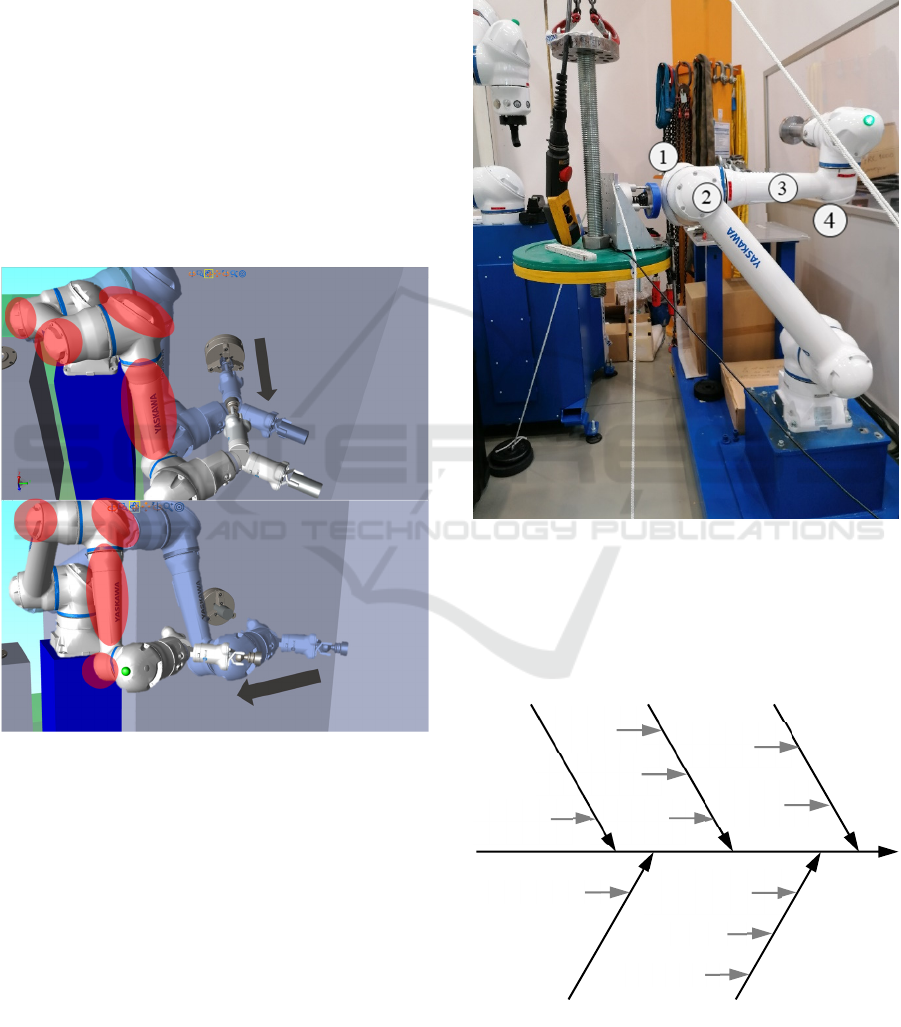
A preliminary risk assessment of lathe machine
tending applications identified multiple transient
contacts based on typical movement sequence
simulations. For both the feed motion (insert and take
out the workpiece) and the movement between door
and feed position, the cobot can collide with the
operator at the marked areas, illustrated in Figure 1.
The transparent position represents the start point,
while the opaque one shows the target coordinate.
Assuming a robot installation on a 900mm high
pedestal, the motions will likely be executed at the
operator's shoulder height. Therefore, this body part
is emphasized in this paper.
Figure 1: Potential Transient Risk Areas.
A Yaskawa HC10DT IP67 cobot installed on a
900mm high pedestal bolted to the ground was used
for the experiments. To replicate the identified values,
the software version YAS4.12.01A(EN/DE)-00 can
be used. For realistic reproduction of the transient
collision case, a special design guarantees free
oscillation and is adjustable in weight to match the
shoulder mass properties of m=40kg. Therefore, a
large locating bolt with a thread was used to install
different weight plates with a screw nut. This unit was
connected to the steel tracks of a 0,5t crane,
minimizing friction and providing a sufficiently long
pendulum. On top of the plates, the measurement
device PILZ PRMS has been fixed using screw
clamps. The pedestal-crane-combination has been
adjusted to simulate a realistic shoulder height of
1450mm. For reproducible results, ropes were
attached to the device to guide the recoil movement
and maintain a certain rebound angle.
Figure 2: Measurement Setup for Shoulder Simulation with
1 Elbow Big Cap, 2 Elbow Small Cap, 3 Forearm and 4
Wrist Cap.
3.2 Considered Influencing Factors
Figure 3: Ishikawa Diagram with Influencing Factors on the
Maximum Allowed Collaborative Speed.
Sensor
Sensitivity
Machine Method
Collision
Case
Contact
Case
Measured
Feature
(Hu)Man
Body Region
Attached
Workpiece
Additional
Padding
Material
Measurement
Spring
Thickness
Damping
Material
ICINCO 2021 - 18th International Conference on Informatics in Control, Automation and Robotics
218
To collect possible influencing factors on the
maximum allowed collaborative speed (MACS), an
Ishikawa diagram has been created based on the 5M’s
machine, method, material, (hu)man, and
measurements. For further specification, detailed
characteristics have been assigned that are used as a
basis for experiment planning and design.
Table 1: Influencing Factors on the Maximum Allowed
Collaborative Speed.
5 M’s Criteria Characteristics
Machine
(Robot)
Robot
Collision
Geometr
y
Elbow Big Cap, Elbow
Small Cap, Forearm,
Wrist Ca
p
Sensor
Sensitivit
y
50N, 100N
Software
Version
YAS4.12.01A(EN/DE)-
00
Method Measured
Feature
Individual
Collision
Case
Transient
(Hu)man Body
Region
Shoulder
Force
Threshol
d
420N
Pressure
Threshol
d
320N/cm
2
Measurement Damping
Material
K1
Shore A 30
S
p
rin
g
K2 35N/m
m
Thickness 14m
m
Material Padding None, Neoprene, Foa
m
3.3 Experimental Design
To cover the predefined risk cases, four different
robot outer contours have been tested regarding
collision forces and pressures: the two elbow caps, the
forearm, and the wrist cap of the cobot (see Figure 2).
This setup was designed to deliver insights on worst-
case scenarios where one of the robot's least favorable
edges collides with the measurement device. While
the hard edge has been used for tests with the big
elbow cap, this type of collision was not reproducible
for the smaller caps since the cap radius does not
allow a collision with the cap edge. Instead, contacts
with the round outer contour of the small caps were
targeted. Therefore, the big elbow cap delivers a
smaller contact area than the small caps. As can be
seen in Figure 1, different movement types are
assigned to the respective contact areas. While tests
with the big elbow cap utilize mainly the 2
nd
robot
axis for linear movement execution, the other cases
predominantly use the 1
st
axis.
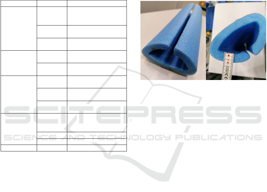
Furthermore, measurements have been conducted
with different protective measures on the collision
surface: no protection, neoprene padding (thickness:
5mm), and foam padding (expanded polyethylene
foam profile, thickness: 140mm, see Figure 4.). While
the neoprene protection was attached with a velcro
fastener, the foam protection had to be attached with
adhesive tape. Using these three different paddings,
the impact of the damping characteristics regarding
material and thickness on the MACS is analyzed.
Figure 4: EPE Foam Profile.
According to DGUV (2017) and ISO/TS 15066
(2016), a spring constant of k=35N/mm, blue silicone
damping material with shore A 30 hardness, and a
thickness of 14mm must be used for the measurement
device to match the shoulder.
According to the PRMS manual, three force
measurements per series are recommended to
counterbalance the device’s inaccuracies. To provide
scientific and statistically valid results, ten
measurements run have been performed. From these
data, the maximal and minimal values each have been
considered as outliers and therefore excluded. Based
on the eight remaining values, the average has been
calculated, which serves as a comparison basis with
the threshold values. The documented average
environment conditions of 60% humidity and 21°C
temperature lie within the stated tolerance of 35%-
80% and 17°C to 35°C. Following the manual, 30
minutes waiting time between pressure foil
measurement and scanning has been adhered to.
For worst-case scenario consideration, a
workpiece with maximum payload utilization was
used. Therefore, a steel shaft with 110mm in
diameter, 230mm in length, and 6,041kg weight was
manufactured and attached.
To determine the MACS, iterative velocity
adjustment loops with a predefined scaling of 10mm/s
led finally to one threshold-compliant and one
violating speed, while the last conform one is the
MACS. For valid results, the distance between the
Empirical Analysis of the Impact of Additional Padding on the Collaborative Robot Velocity Behavior in Transient Contact Cases
219
programmed start and endpoint must be sufficiently
high to guarantee that the robot reaches its predefined
velocity. Furthermore, the second coordinate must lie
at a fair distance behind the collision point to avoid
decelerating the cobot before impact. Correct
configured tool data and regularly calibrated torque
sensors ensure consistent measurement quality. As
robot-dependent factors, different sensor sensitivity
settings, adjustable in the safety controller with force
limits in N, were used. For this research, 100N and
50N were considered.
4 RESULTS
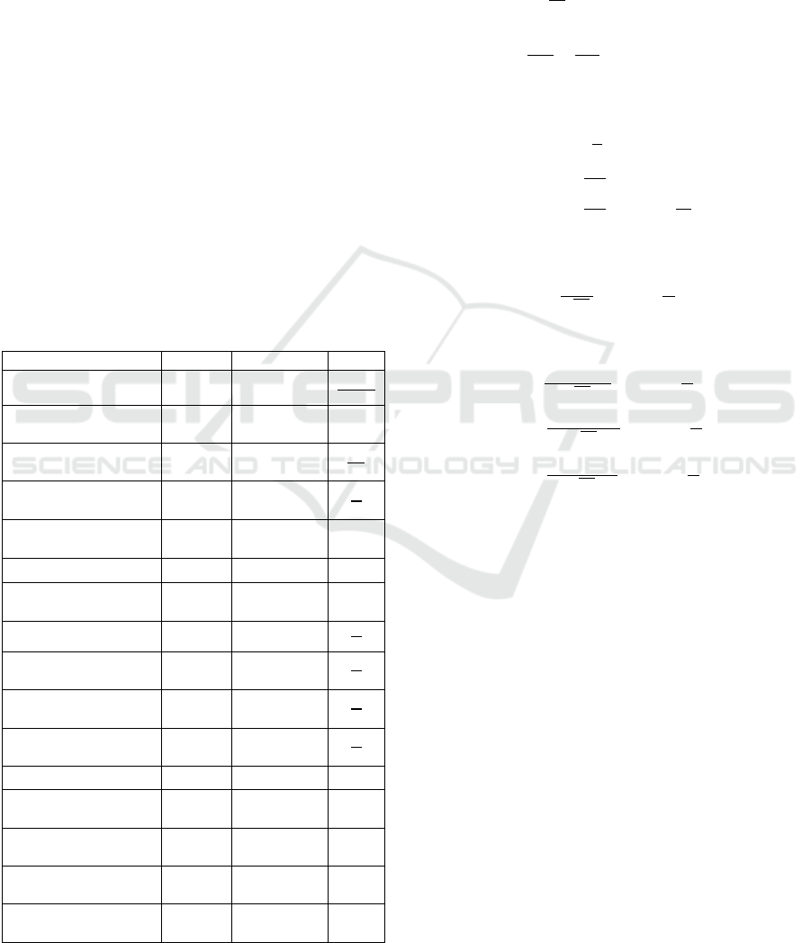
4.1 Theoretical Considerations
Firstly, the MACS will be determined by applying the
respective equations defined in ISO/TS 15066. Table
2 shows the relevant factors and obtained input data
for the human shoulder joint as well as the selected
robot contact areas.
Table 2: Factors for Transient Velocity Calculations.
Facto
r
Symbol Value Unit
Transfer Energy
𝐸 2,5
∗
Maximum Contact
Force
𝐹
420 𝑁
Maximum Contact
Pressure
𝑝
3.200.000
Effective Spring
Constant
𝑘 35.000
Contact Area Elbow
𝐴
1,05
∗10
𝑚
Contact Area Arm
𝐴
1,6∗10
𝑚
Contact Area Cap
𝐴
9,621
∗10
𝑚
Relative Speed
𝑣
calculated
Allowed Speed
Robot Elbow
𝑣
calculated
Allowed Speed
Robot Ar
m
𝑣
calculated
Allowed Speed
Robot Ca
p
𝑣
calculated
Reduced Mass
𝜇 calculated 𝑘𝑔
Effective Mass of the
Human Bod
y
Re
g
ion
𝑚
40 𝑘𝑔
Effective Mass of the
Robot
𝑚
calculated 𝑘𝑔
Effective Payload of
the Robot System
𝑚
6,041 𝑘𝑔
Total Mass of
Movin
g
Robot Parts
𝑀 58 𝑘𝑔
Based on this information, the MACS of the transient
contact case is calculated based on energy, maximum
permissible force, and maximum permissible
pressure. These results will be compared and
discussed with experimentally measured values.
Preliminary Calculations:
𝑚
=
𝑀
2
+𝑚
=35,041𝑘𝑔
(1)
𝜇=
1
𝑚
+
1
𝑚
=18,678𝑘𝑔
(2)
Calculations based on Energy:
𝐸=
1
2
𝜇𝑣
(3)
𝑣
=
2𝐸
𝜇
=0,517
𝑚
𝑠
(4)
Calculations based on Permissible Force:
𝑣
=
=0,519
(5)
Calculations based on Permissible Pressure:
𝑣
=
∗
=0,415
(6)
𝑣
=
∗
=6,332
(7)
𝑣
=
∗
=3,808
(8)
While the energy- and force-based calculations lead
to nearly similar results, the pressure-based
calculations deviate with a factor between 0,8 and
12,3. Consequently, the forces and energies are the
theoretical limiting factors, while pressure could be
strongly increased according to the calculated results.
4.2 Experiment on Elbow Big Cap
Without protective measures, the maximum speed is
mainly restricted by the pressure limit, which has
been surpassed at 70mm/s, leading to a MACS of
60mm/s. However, with protective measures, the
MACS climbs up to 720mm/s with neoprene and
770mm/s with foam padding. This can be explained
by an even pressure distribution on a greater surface
compared to measurements without protection.
Furthermore, the MACS with a force limit of 50N
was slightly higher than measurements with 100N for
protective measures while having no effect when
using no padding.
ICINCO 2021 - 18th International Conference on Informatics in Control, Automation and Robotics
220
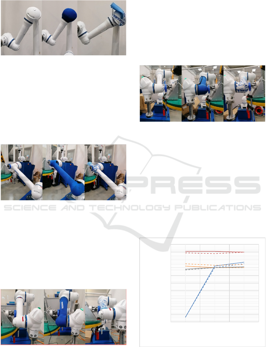
Figure 5: Setup for Elbow Big Cap.
4.3 Experiment on Elbow Small Cap
The pressure threshold has not been reached in this
experiment for all three setups, while the force has
been exceeded at 890mm/s to 920mm/s depending on
the used padding. Measurement results with 50N
deliver higher MACS compared to the 100N force
limit, irrespective of the protective measures. No
clear tendency on the dependency of MACS and the
protective measure could be identified.
Figure 6: Setup for Elbow Small Cap.
4.4 Experiment on Forearm
Pressure thresholds were undercut with all
measurement series. The highest MACS have been
registered for 100N force limit and measurement
without protection at 750mm/s. With a force limit of
50N, the MACS could not be reached for neoprene
and foam protection since the high torque sensor
sensitivity triggers a protective stop of the robot
during high acceleration.
Figure 7: Setup for Forearm.
4.5 Experiment on Wrist Cap
As expected, observed MACS are lower than those of
the small elbow cap because the collision point is
further away from the robot base resulting in a higher
lever. The highest MACS was registered for the 50N
force limit in combination with foam protection.
Without protection, results were lower for both sensor
sensitivities.
Figure 8: Setup for Wrist Cap.
4.6 Summary
Additional padding on the respective collision surface
can drastically increase the maximum allowed
collaborative speed, if critical areas with small
surfaces (big elbow cap) are present. For the other
three cases, a clear influence of protective measures
on the MACS could not be verified. Whereas the
neoprene cover could not evidently reduce occurring
force compared to the setup without protection,
attaching EPE foam profiles on the collision surface
showed significant force reduction. Overall, the
pressure threshold has been exceeded only for the big
elbow cap without padding.
Figure 9: MACS by Protective Measures and Force Limit:
50N – Full, 100N – Dotted, Elbow Big Cap – Blue, Elbow
Small Cap – Red, Forearm – Green, Wrist Cap – Black.
0
100
200
300
400
500
600
700
800
900
1000
None Neoprene Foam
MACS [mm/s]
Protective Measure
Empirical Analysis of the Impact of Additional Padding on the Collaborative Robot Velocity Behavior in Transient Contact Cases
221

5 CONCLUSIONS
In this paper, the influence of additional padding in
transient contact cases has been analyzed. Based on
the use case of lathe machine tending, different
contact cases were concluded in a preliminary risk
assessment, based on the required movements with
the respectively affected robot geometries as an
interfering contour. As a realistic body region, the
shoulder was assumed to collide with the robot during
either a feed motion between the machine’s door and
spindle feed position or between spindle feed and
spindle position. To cover robot-specific influencing
factors, force limits of 50N and 100N were tested. As
theoretical fundament, the maximum allowed
collaborative velocities were calculated with the
equations defined in ISO/TS 15066. A high result
deviation has been demonstrated depending on the
used metric (energy, force or pressure). Comparisons
to the empirically determined MACS values show
differences of 0,25m/s to 0,46m/s for the big elbow
cap, 0,38m/s to 2,91m/s for the elbow small cap,
0,18m/s to 5,6m/s for the forearm and 0,15m/s to
3,14m/s for the wrist cap. Due to the used test setup,
measurement deviations can be traced back to the
oscillation of the hanging construction during a
collision and the result accuracy of the pressure-
sensitive foils. The force limit settings (sensor
sensitivity) showed a small impact on the result since
the robot stops immediately when colliding.
Experiments on the forearm with a 50N force limit
were not feasible due to the robot sensors' self-
triggering at high velocities.
This study was executed with a selected cobot and
is therefore exclusively valid for this model. To help
building a broader database of the maximum allowed
collaborative speeds and to understand various
influencing factors, similar tests with other cobot
models are required in the future. For safety
engineering, this data would serve as a tool to
facilitate the risk assessment effort on-site to reduce
certification time and cost. Increased precision in the
upfront determination of compliant speeds improves
investment reliability since cycle times can be
approximated in an early project stage. Such a
database supports performance transparency of
different robot models regarding achievable cycle
times and helps the robot planner and end-user select
the most profitable cobot. Lastly, robot manufacturers
gain valuable insights for further R&D activities to
improve their products.
ACKNOWLEDGEMENTS
We thank Dr.-Ing. Roland Behrens (Fraunhofer IFF)
for consulting throughout the project, especially
regarding the measurement setup's suitability.
REFERENCES
Behrens, R.; Pliske, G. (2019): Human-Robot
Collaboration: Partial Supplementary Examination [of
Pain Thresholds] for Their Suitability for Inclusion in
Publications of the DGUV and Standardization.
Fraunhofer IFF, Otto von Guericke University Trauma
Surgery Clinic.
BIS Research (2016): Global Collaborative Robot
Hardware Market, Analysis & Forecast, 2016-2021
(Focus on Major Industries and Applications). BIS
Research. Available online at https://bisresearch.com/
industry-report/global-cobots-market-report-
forecast.html, checked on 5/14/2021.
Chemweno, P.; Pintelon, L.; Decre, W. (2020): Orienting
safety assurance with outcomes of hazard analysis and
risk assessment: A review of the ISO 15066 standard
for collaborative robot systems. In Safety Science 129.
DOI: 10.1016/j.ssci.2020.104832.
DGUV (2017): Collaborative robot systems: Design of
systems with "Power and Force Limiting" function.
Available online at https://www.dguv.de/medien/fb-
holzundmetall/publikationen-
dokumente/infoblaetter/infobl_englisch/080_collabora
tiverobotsystems.pdf, updated on 08/2017, checked on
3/12/2021.
Eder, K.; Harper, C.; Leonards, Z. (Eds.) (2014): Towards
the Safety of Human-in-the-Loop Robotics: Challenges
and Opportunities for Safety Assurance of Robotic Co-
Workers. The 23rd IEEE International Symposium on
Robot and Human Interactive Communication.
Edinburgh, UK, 25-29 Aug. 2014: IEEE.
Fraunhofer Institute for Industrial Engineering IAO
(2016): Lightweight robots in manual assembly - best
to start simply! Edited by W. Bauer, M. Bender, M.
Braun, P. Rally, O. Scholtz. Available online at
https://www.produktionsmanagement.iao.fraunhofer.d
e/content/dam/produktionsmanagement/de/documents/
LBR/Studie-Leichtbauroboter-Fraunhofer-IAO-2016-
EN.pdf, checked on 5/13/2021.
Ganglbauer, M.; Ikeda, M.; Plasch, M.; Pichler, A. (2020):
Human in the loop online estimation of robotic speed
limits for safe human robot collaboration. 30th
International Conference on Flexible Automation and
Intelligent Manufacturing (FAIM2021). In Procedia
Manufacturing 51, pp. 88–94. DOI: 10.1016/j.promfg.
2020.10.014.
Haddadin, S.; Albu-Schäffer, A.; Hirzinger, G. (2011): Safe
Physical Human-Robot Interaction: Measurements,
Analysis and New Insights. In Robotics Research,
pp. 395–407. DOI: 10.1007/978-3-642-14743-2_33.
ICINCO 2021 - 18th International Conference on Informatics in Control, Automation and Robotics
222

Haddadin, S.; De Luca, A.; Albu-Schäffer, A. (2017):
Robot Collisions: A Survey on Detection, Isolation, and
Identification. In IEEE Transactions on Robotics 33 (6),
pp. 1292–1312. DOI: 10.1109/TRO.2017.2723903.
Kovincic, N.; Gattringer, H.; Müller, A.; Weyrer, M.;
Schlotzhauer, A.; Kaiser, L.; Brandstötter, M. (2019):
A model-based strategy for safety assessment of a robot
arm interacting with humans. In Proceedings in Applied
Mathematics & Mechanics. DOI: 10.1002/pamm.
201900247.
Lasota, P. A.; Fong, T.; Shah, J. A. (2014): A Survey of
Methods for Safe Human-Robot Interaction. In
Foundations and Trends 5 (4), pp. 261–349. DOI:
10.1561/9781680832792.
Marvel, J.; Bostelman, R. (2014): A Cross-domain Survey
of Metrics for Modelling and Evaluating Collisions. In
International Journal of Advanced Robotic Systems 11.
DOI: 10.5772/58846.
Robla-Gómez, S.; Becerra, V. M.; Llata, J. R.; González-
Sarabia, E.; Torre-Ferrero, C.; Pérez-Oria, J. (2017):
Working Together: A Review on Safe Human-Robot
Collaboration in Industrial Environments. In IEEE
Access 5, pp. 26754–26773. DOI: 10.1109/ACCESS.
2017.2773127.
ISO/TS 15066:2016, 2016: Robots and robotic devices -
Collaborative robots.
Shin, H.; Kim, S.; Seo, K.; Rhim, S. (Eds.) (2019): A Real-
Time Human-Robot Collision Safety Evaluation
Method for Collaborative Robot. 3rd IEEE
International Conference on Robotic Computing (IRC).
Naples, Italy, 25.02.-27.02.: IEEE.
Svarny, P.; Rozlivek, J.; Rustler, L.; Hoffmann, M. (2020):
3D Collision-Force-Map for Safe Human-Robot
Collaboration (Preprint).
Vemula, B.; Matthias, B.; Ahmad, A. (2018): A design
metric for safety assessment of industrial robot design
suitable for power‑ and force‑limited collaborative
operation. In International Journal of Intelligent
Robotics and Applications 2, pp. 226–234. DOI:
10.1007/s41315-018-0055-9.
Villani, V.; Pini, F.; Leali, F.; Secchi, C. (2018): Survey on
human–robot collaboration in industrial settings: Safety,
intuitive interfaces and applications. In Mechatronics
55, pp. 248–266. DOI: 10.1016/j.mechatronics.2018.
02.009.
Weitschat, R. (2019): Industrial Human-Robot
Collaboration: Maximizing Performance While
Maintaining Safety. Dissertation. Universität Rostock.
Fakultät für Maschinenbau und Schiffstechnik.
Yen, S.-H.; Tang, P.-C.; Lin, Y.C.; Lin, C.-Y. (2019):
Development of a Virtual Force Sensor for a Low-Cost
Collaborative Robot and Applications to Safety Control.
In Sensors 19 (11). DOI: 10.3390/s19112603.
Empirical Analysis of the Impact of Additional Padding on the Collaborative Robot Velocity Behavior in Transient Contact Cases
223
