
Design Optimization of a Manipulator for CERN’s Future Circular
Collider (FCC)
Hannes Gamper
1,2
a
, Hubert Gattringer
2 b
, Andreas M¨uller
2 c
and Mario Di Castro
1 d
1
BE-CEM-MRO, CERN - European Organization for Nuclear Research, Espl. des Particules 1, 1211 Meyrin, Switzerland
2
Institute of Robotics, Johannes Kepler University, Altenbergerstraße 69, 4040 Linz, Austria
Keywords:
Design Optimization, Redundant System, Manipulator.
Abstract:
CERN is often confronted with very specialized automation problems in hazardous, radioactive and semi-
structured environments for its particle accelerators, test rigs or other experiments. These frequently lead to
specific requirements that do not allow the usage of common industrial robots. Thus, a design problem with
almost no restrictions on the actual robot topology, but very hard requirements concerning workspace, allowed
robot space, payload, robot weight and accuracy (due to elasticity/error propagation) has to be solved. This
paper reports an approach to this problem, which was applied to find an optimal robotic design for inspection
and maintenance tasks in CERN’s Future Circular Collider (FCC).
1 INTRODUCTION
Since being founded in 1954, CERN - European Or-
ganization for Nuclear Research has been a continu-
ously successful institution for particle physics, con-
tributing major steps to complete the Standard Model
of Particle Physics. The consecutive particle accel-
erators PS (Proton Synchrotron), SPS (Super Proton
Synchrotron) and LHC (Large Hadron Collider) with
their increasing center of mass collision energy of 50
GeV, 900 GeV and 14 TeV and corresponding in-
crease in circumference of 628 m, 6.9 km and 27 km,
were directly related to the award of the Nobel Prize
in 1979 (PS), 1984 (SPS) and 2013 (LHC). The latter
nobel prize was related to the discovery of the Higgs-
Boson, which was predicted almost 50 years before
its detection at CERN by Peter Higgs and thus com-
pleted the most precise model of our universe so far,
the Standard Model of Particle Physics.
Yet, there are still phenomena, like dark matter,
the prevalence of matter over antimatter or the neu-
trino mass, which cannot be described by the Stan-
dard Model. This suggests, that there must be more,
physics which goes beyond the Standard Model and
still has to be discovered. A good chance to unveil
a
https://orcid.org/0000-0001-5522-734X
b
https://orcid.org/0000-0002-8846-9051
c
https://orcid.org/0000-0001-5033-340X
d
https://orcid.org/0000-0002-2513-967X
such behavior is thought to lie in particles with a mass
above 14 TeV and thus unable to be created by the
current machines at CERN. To unlock observations
in these high energy ranges, a new particle acceler-
ator with a center of mass energy of 100 TeV and a
circumference of 100 km was suggested: the Future
Circular Collider - FCC.
Figure 1: PS, SPS, LHC and FCC comparison.
In 2013 the European Strategy for Particle Physics
initiated a Conceptual Design Report and feasibil-
ity study on the FCC. Since then numerous physics
studies about possible future discoveries, the most
promising energy ranges and the underlying theories,
as well as engineering studies about possible con-
struction sites, logistics, material research, automa-
320
Gamper, H., Gattringer, H., Müller, A. and Di Castro, M.
Design Optimization of a Manipulator for CERN’s Future Circular Collider (FCC).
DOI: 10.5220/0010601803200329
In Proceedings of the 18th International Conference on Informatics in Control, Automation and Robotics (ICINCO 2021), pages 320-329
ISBN: 978-989-758-522-7
Copyright
c
2021 by SCITEPRESS – Science and Technology Publications, Lda. All rights reserved

tion techniques and socio-economicstudies looking at
the impact of a 9 GCHF science project in the middle
of Europe, were conducted in collaborations of over
150 universities and finally published in 2019 within
the Conceptual Design Report for a Lepton (FCC-ee)
and Hadron (FCC-hh) Collider in (CDR, 2019a) and
(CDR, 2019b). The 2020 Update of the European
Strategy for Particle Physics listed the further investi-
gation of the FCC as one of three main priorities and
thus launched a Technical Design Report.
At this stage, in-depth studies like geodetic mea-
surements for possible placements of the tunnel,
structural simulations, material handling during con-
struction, power supply, emergency scenarios and
many more are conducted to estimate feasibility, cost
and construction time. One of these studies concerns
the automation of maintenance, inspection and emer-
gency handling along the 100 km long FCC tunnel.
The automation of these tasks plays a significant role
for downtime, reliability and safety of particle accel-
erators and decreases the radiation exposure of work-
ers. Since these tasks require various adept mechan-
ical interactions with its environment in a huge work
space, the study suggested a rail-based robotic system
with a highly redundant manipulator for the FCC tun-
nel.
Based on this suggestion for a generic robot
layout, this paper presents the applied methods to
find a robot design with low production costs, low
robot weight and lowest possible energy consump-
tion, while providing the required precision. Further-
more the robot needs to perform most diverse kinds of
operations from maintenance over inspection to emer-
gency handling, while moving in the complex envi-
ronments of the FCC-ee and FCC-hh tunnels.
In section 2 the environment, given tasks and de-
rived requirements are presented. Some assumptions
and an initial, tentative robot topology are shown in
section 3. Section 4 describes the modelling of the
robot, optimization techniques and objectives as well
as the final optimal robot topology. Then, in section
5 the prototype for future proof of concept studies is
presented and the last section 6 discusses the conclu-
sions drawn from this work.
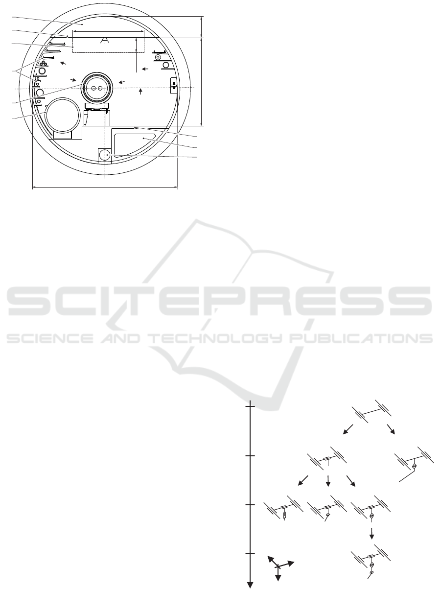
2 ENVIRONMENT & TASKS
The FCC tunnel will have an inner diameter of 5.5
m and host two different configurations, first a lepton
collider (the FCC-ee) and then a hadron collider (the
FCC-hh) shown in figures 2 and 3, respectively.
The upper section A of the tunnel is separated
by the ceiling B and will be used for smoke and he-
lium extraction in case of emergencies. The ceiling B
will also function as the support structure for the rail-
based robotic system. Several fire doors divide the
tunnel into about 400 m long sections, through which
the robot can pass via automated hatches. Thus, the
robot space is limited to the area C, when traveling
along the tunnel axis. Further installation material D
like cable trays, fiber optics, helium recovery, com-
pressed air and water pipes are placed on the left and
right side of the cross-section. The floor G consists
of reinforced concrete and embeds a fresh air duct H
and a water drain I. The FCC-ee layout furthermore
contains the booster ring E and the e+/e- ring F and
the FCC-hh layout the cryostat J and the cryogenic
distribution line K.
A
B
C
D
E
F
G
H
I
5.5
2.9
0.55
3.35
0.8
I
II
III
IV
Figure 2: Cross-section FCC-ee.
In these environments the robotic system has to
be able to handle different maintenance and inspec-
tion tasks. This requires the robot to reach a specific
position and orientation (indicated with arrows in fig-
ures 2 and 3) while providing the necessary precision.
The most diverse tasks, based on experience from in-
terventions in the LHC, are:
• BLM Inspection (I): The Beam-Loss-Monitor
sensors, described in (Holzer et al., 2012), on the
right and left side of E and J, detect the loss of
particles of the beam. These sensors need to be
tested regularly by approaching them with a ra-
dioactive source while reading the sensor values.
• Vacuum Leak Detection (II): Loss of the vac-
uum in the cryostats can lead to fatal destruction,
see incident in 2008 (M. Bajko, 2009). In case
the vacuum pumps detect a leak, the robot has to
move to the corresponding section and inject he-
Design Optimization of a Manipulator for CERN’s Future Circular Collider (FCC)
321
replacements
A
B
C
D
J
K
G
H
I
5.5
2.9
0.55
3.35
0.8
I
II
III
IV
V
Figure 3: Cross-section FCC-hh.
lium at critical parts of the installation. Once the
vacuum pumps detect helium, the location of the
leak can be narrowed down until it is found.
• General Exceptional Inspections (III): In case
of exceptional problems like failure of certain sys-
tems of the complex installations, the robot needs
to inspect the tunnel immediately and save work-
ers from possible hazards.
• Radiation Measurement (IV): Before workers
are allowed in the tunnel after a shut down of the
machine, the radiation levels along the tunnel axis
will be measured, recorded and analyzed. Related
systems in the LHC are presented in (Castro et al.,
2018).
• Alignment Measurement (V): The cryostats, E
and J, need to be aligned with high precision, to
avoid potential beam loss. The alignment process
and algorithms are described in (Missiaen et al.,
2009) and (Valentino et al., 2012). To measure the
alignment, a system of fiducials on the cryostats
has to be detected and the relative position be-
tween consecutive elements will be measured, see
(Bestmann, 2008).
The points discussed above give rise to certain re-
quirements and restrictions, which are relevant for the
topology of the robotic system:
1. A workspace of 5.5 × 3.35 m along the 100 km
long tunnel.
2. Pass through fire door hatches with dimensions of
2.9× 0.55 m.
3. Reach necessary positions according to the tasks.
3 MANIPULATOR DESIGN
CONCEPT
The aim is to find the best-suited manipulator, based
on the recommendation for a rail-based robotic sys-
tem with a highly redundant manipulator by the con-
ducted survey and the requirements and restrictions
discussed in section 2. The manipulator is concep-
tually split up into a positioning mechanism (section
3.1) and a subsequent dexterous arm (section 3.2).
The positioning mechanism serves to position and
align the arm within the FCC tunnel. The dexterous
arm will enable the robot to perform complex han-
dling tasks while avoiding obstacles.
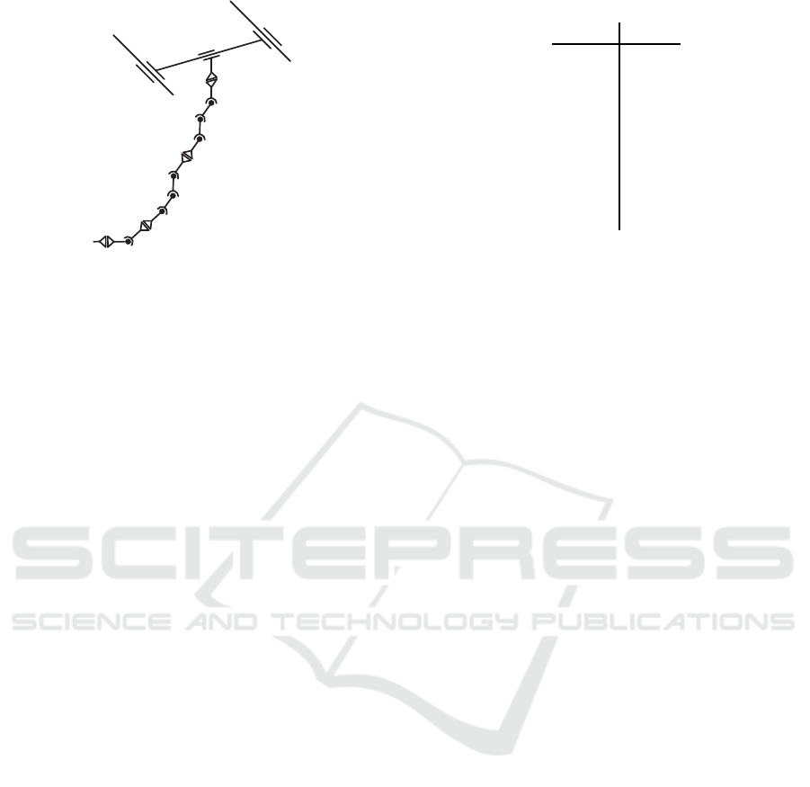
3.1 Positioning Mechanism
The topology of the first four joints was rather ob-
vious and could be found by a manual exploration
of possible joint configurations. Figure 4 shows the
possible variants Vi for each of the four joints J1 to
J4. The following enumeration discusses the pros and
cons of the different variants for each joint:
1. Joint 1 in figure 4, implements a linear movement
in direction of the tunnel axis (y-axis) according
to the recommendation of a rail-based system.
2. Joint 2 spans the xy-plane by either introducing
another linear movement in x-direction (J2V1) or
a rotation around z-axis including an offset for the
following robot link (J2V2). J2V1 requires less
space and will increase the dexterity of the ma-
nipulator.
Joint
J1
J2
J3
J4
x
y
z
V1
V1
V1
V1
V2
V2
V3
Figure 4: Possible configurations of the first four joints.
ICINCO 2021 - 18th International Conference on Informatics in Control, Automation and Robotics
322
11
1
2
3
4
5
6
7
8
9
10
1213
E
Figure 5: Tentative topology.
3. J3V1 would add a translation in z-direction to
span the xyz-volume, but dimensions of currently
available technical solutions do not comply with
point 2 in section 2. J3V2 introduces a rota-
tion around y-axis to span the xyz-volume, but the
missing degree of freedom around z-axis for the
consecutive robot link limits the dexterity heav-
ily, especially in complex workspaces with obsta-
cles. The rotation of J3V3 around the z-axis does
not extend the reachable work-space as the other
versions, but it leads to a more versatile structure
overall.
4. In J4V1 the rotation around the x-axis is imple-
mented to span the xyz-volume.
Thus the tentative topology for the positioning
mechanism is defined by the joints J1V1 − J2V1 −
J3V3− J4V1.
3.2 Dexterous Arm
To fulfill all requirements the minimal degrees of free-
dom (DoF) is at least 8, where 6 are necessary to
reach every point in space in any given orientation
and an additional 2 DoF are needed to avoid the a-
priori known obstacles. Also, this would only be true
if there were no geometric restrictions on the robot
design, but the maximum length of the robot links
are limited on one hand by the maximum torque in
the corresponding joints and on the other hand by the
space (described in section 2) that the folded robot
is allowed to occupy while passing through the fire
doors. Additionally the FCC tunnel cross-section is
semi-structured and thus the robot must be able to
avoid obstacles which are not known a-priori.
This suggests the introduction of additional DoF,
but a general judgment without simulations has, with
increasing DoF, already become very tedious. There-
fore, a tentative robot topology, with a higher DoF
Table 1: Tentative geometry.
length
[mm]
l
1,2
var.
l
2,4
288
l
4,5
500
l
5,6
500
l
6,8
400
l
8,9
400
l
9,10
400
l
10,12
200
l
12,E
100
than the expected optimal solution was set up as a
starting point for a subsequent design optimization,
see figure 5. The initial geometry is shown in table 1,
with the variables l
i, j
representing the lengths of the
manipulator links from joint i to joint j.
The first four joints correspond to the configura-
tion in figure 4. To allow the mechanical structure to
fold up in the desired area, joints 5 and 6 were chosen
in such a way that they, together with joint 4, form
a planar mechanism, which can be folded up easily.
The motion plane of this mechanism can be rotated
by joint 3. For the consecutive joints 7 to 10, the
same planar mechanism was repeated to be able to
fold the robot within the very limited space described
in section 2. The last three joints 11, 12 and 13 are
chosen in such a way that their rotation axes intersect
at only one point and thus the solution for orientation
and position can be decoupled, which simplifies the
optimization problem later on. This configuration of
joints also resembles a typical robotic wrist. In sec-
tion 4 the tentative design will be optimized in order
to provide the best manipulator design for the FCC
tunnel.
4 DESIGN OPTIMIZATION
In this section the tentative and thus, non-optimal
robot topology and geometry of figure 5 and table 1
will be modified, such that the final result provides
an optimal and practical feasible solution with respect
to certain objectives. The desired goals are minimal
production cost and mass, lowest possible energy con-
sumption and high precision. These can be translated
into the following optimization objectives:
• Minimize the DoF.
• Minimize the length of each robot link.
• Minimize the motor torques.
• Minimize the error propagation over the mechan-
ical structure.
Design Optimization of a Manipulator for CERN’s Future Circular Collider (FCC)
323
These objectives need to be constrained in a way,
such that the robot is able to reach all desired po-
sitions, avoid collisions and can be folded up to fit
through the hatches in the fire doors. Similar de-
sign optimization problems concerning manipulabil-
ity measures, error measures and torque minimization
are discussed in (Bi and Zhang, 2001) and (Van Hen-
ten et al., 2009), but without minimizing the DoF of
the mechanical structure.
In section 4.1 a parametrized model of the tenta-
tive robot shown in figure 5 and table 1, including
kinematics and dynamics, will be defined. The ap-
plied collision environment is shown in section 4.2
and the definition of the optimization problem and
strategy is shown in section 4.3. The optimized robot
design is shown in section 4.6.
4.1 Model
The forward kinematics f : R
DoF
→ R
6
can be written
in the form
z = f(q), (1)
with the generalized joint coordinates q ∈ R
DoF
and the Cartesian position and orientation z ∈ R
6
.
An explicit solution for the inverse kinematics is not
needed, since it will be taken into account by non-
linear equality constraints in the optimization prob-
lem.
The dynamic model was found by applying the
projection equation (Gattringer, 2011)
N
∑
i=1
A
i
z
}| {
"
∂
R
v
IS
∂
˙
q
T
∂
R
ω
IS
∂
˙
q
T
#
i
R
˙
p+
R
e
ω
IR R
p−
R
f
e
R
˙
L+
R
e
ω
IR R
L−
R
M
e
i
|
{z }
B
i
= 0, (2)
with the absolute, linear and angular center of mass
velocities
R
v
IS
and
R
ω
IS
, represented in the body-
fixed coordinate frame R, relative to the inertial co-
ordinate frame I. The linear and angular momentum,
represented in the body-fixed coordinate frame R
R
p
R
L
=
mI 0
0
R
J
S
R
v
IS
R
ω
IS
(3)
with the identy matrix I, the mass m and the inertia
tensor at center of mass
R
J
S
in frame R. The acting
forces and torques
R
f
e
and
R
M
e
on the sub-system and
cross product matrix
ω =
ω
x
ω
y
ω
z
and
e
ω =
0 −ω
z
ω
y
ω
z
0 −ω
x
−ω
y
ω
x
0
(4)
The term B
i
in (2) is the linear and angular momentum
for each sub-system, consisting of motor and link, can
be independently expressed with respect to the body-
fixed coordinate frame of the respective sub-system.
The term A
i
transforms the momentum of every sub-
system according to the directions of free motion, de-
pending on the mechanical constraints of each joint.
Summing up over all N sub-systems finally leads to
the equation of movement for the entire robot
M(
˙
q)
¨
q+ g(q,
˙
q) = Q, (5)
with the mass matrix M, the non-linear term g(q,
˙
q)
containing gravitational, centrifugal and coriolis
terms and the actuator forces and torques Q.
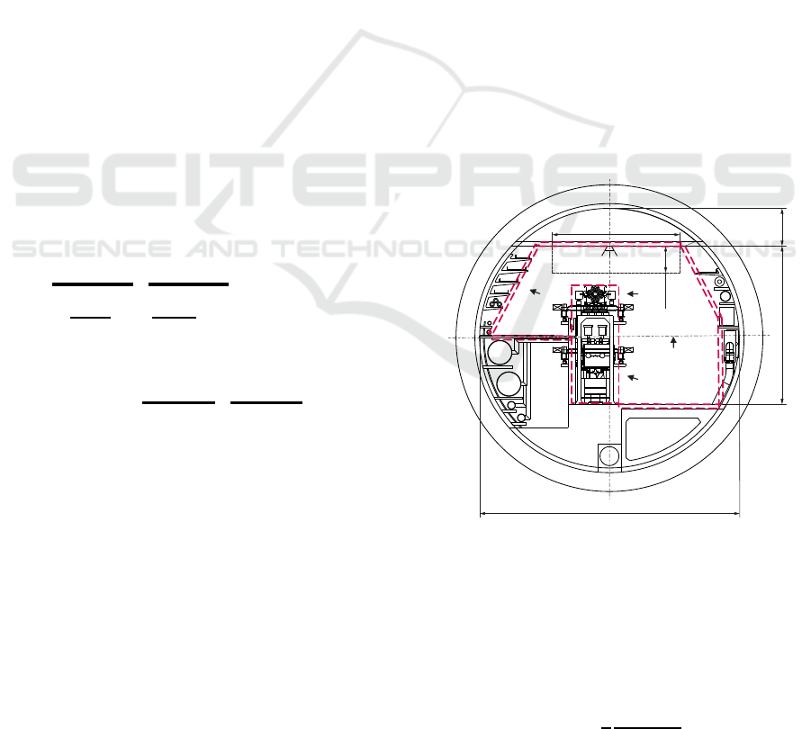
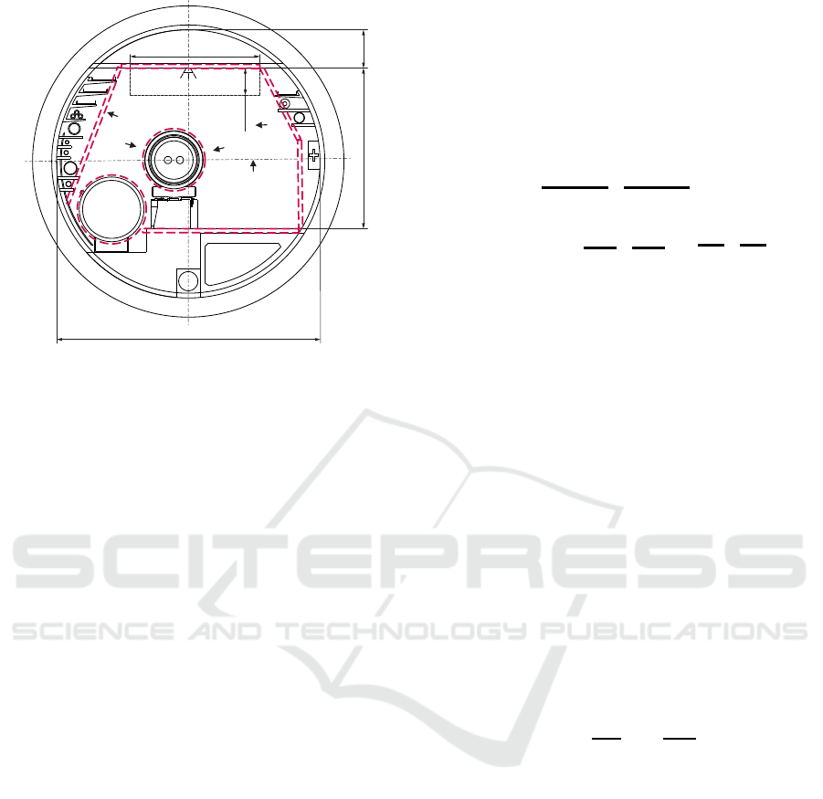
4.2 Collision Avoidance
The environment of the FCC tunnel cross-sections
and the robot links were approximated by convex
geometric primitives, here specifically Matlab’s Al-
phaShapes (The MathWorks Inc., 2019), which can
be passed to a function to calculate the minimal dis-
tance between two convex geometric primitives. The
approximation of the FCC environment with cylin-
ders and boxes is indicated by red, dashed lines in
figures 6 and 7.
5.5
2.9
0.55
3.35
0.8
I
II
III
IV
Figure 6: Collision elements FCC-ee.
To reduce the computational cost of the simula-
tion, it was assumed that two consecutive links of a
robot can either mechanically not collide or the col-
lision avoidance is included in the upper and lower
bounds of the corresponding joint angles. Thus, the
n
R
serial link robot has to avoid
c
RR
=
1
2
n
R
!
(n
R
− 2)!
(6)
ICINCO 2021 - 18th International Conference on Informatics in Control, Automation and Robotics
324
5.5
2.9
0.55
3.35
0.8
I
II
III
IV
V
Figure 7: Collision elements FCC-hh.
possible self collisions and in general
c
RE
= n
R
n
E
(7)
collisions with the environment. The approximation
of the geometry of the manipulator itself can be seen
in the final results in figures 11 and 12.
4.3 Problem Formulation
The optimization problem was set up as a non-linear
global optimization with non-linear equality and in-
equality constraints
min
x, p
l
J(x, p
l
)
s.t. f(x, p
l
) − z
des
= 0
−c(x, p
l
) ≤ 0
ub(x, p
l
) ≤ 0
lb(x, p
l
) ≤ 0
(8)
with the objective function J (x, p
l
) (see section 4.4)
and the parameters x and p
l
. The vector x contains
the general coordinates for n
pos
positions defined in
section 2. The vector p
l
contains the geometric pa-
rameters, in this case the lengths of the n
par
robot
links. Thus, x =
q
T
1
, q
T
2
, ..., q
T
n
pos
T
∈ R
(n
DoF
n
pos
)×1
and p
l
∈ R
n
par
×1
.
The inverse kinematics is solved with the equal-
ity constraint f(x, p
l
) − z
des
= 0, since it is setting
the distance between the actual forward kinematics
and the desired Cartesian positions and orientations to
zero. The vector c(x, p
l
) ∈ R
(c
RR
+c
RE
)×1
contains
the minimal distances according to self-collisions
and collisions with the environment. The vectors
ub(x, p
l
), lb(x, p
l
) ∈ R
(n
DoF
n
pos
+n
par
)×1
are up-
per and lower boundaries to the joint angles and link
lengths.
4.4 Objective Function
As already discussed at the beginning of section 4, the
desired objective function should minimize the DoF,
the robot link lengths, the torques and the error propa-
gation. This is expressed as linear combination of the
multiple objectives
J(x, p
l
) = Q
T
(x, p
l
)K
Q
Q(x, p
l
)
|
{z }
J
1
+ k
T
p
arctan(p
l
)
|
{z }
J
2
+k
T
w
w(x, p
l
)
|
{z }
J
3
. (9)
In the following sections 4.4.1 to 4.4.3 the effect
of each term on the optimization result will be dis-
cussed. The vector of torques Q ∈ R
(n
DoF
n
pos
)×1
ac-
cording to (5), is weighted with the diagonal matrix
K
Q
∈ R
(n
DoF
n
pos
)×(n
DoF
n
pos
)
. The second term penal-
izes the length of the robot links with the weighting
factor k
p
∈ R
n
par
×1
and the third term penalizes the
error propagation with the directional kinematic ma-
nipulability measure and the corresponding weighting
vector w =
w
1
, w
2
, ..., w
n
pos
T
, k
w
∈ R
n
pos
×1
. The
directional kinematic manipulability measure (Nait-
Chabane et al., 2007) can be written as
w
j
=
3
∑
i=1
n
T
j
u
j,i
σ
j,i
, (10)
with the unit vector n
j
representing the direction of
interest and the major and minor axes of the manip-
ulability ellipsoid σ
j,i
u
j,i
obtained from the singular
value decomposition of the geometric Jacobian
J
j
(q
j
, p
l
) =
"
∂v
E
∂
˙
q
T
∂ω
E
∂
˙
q
T
#
T
. (11)
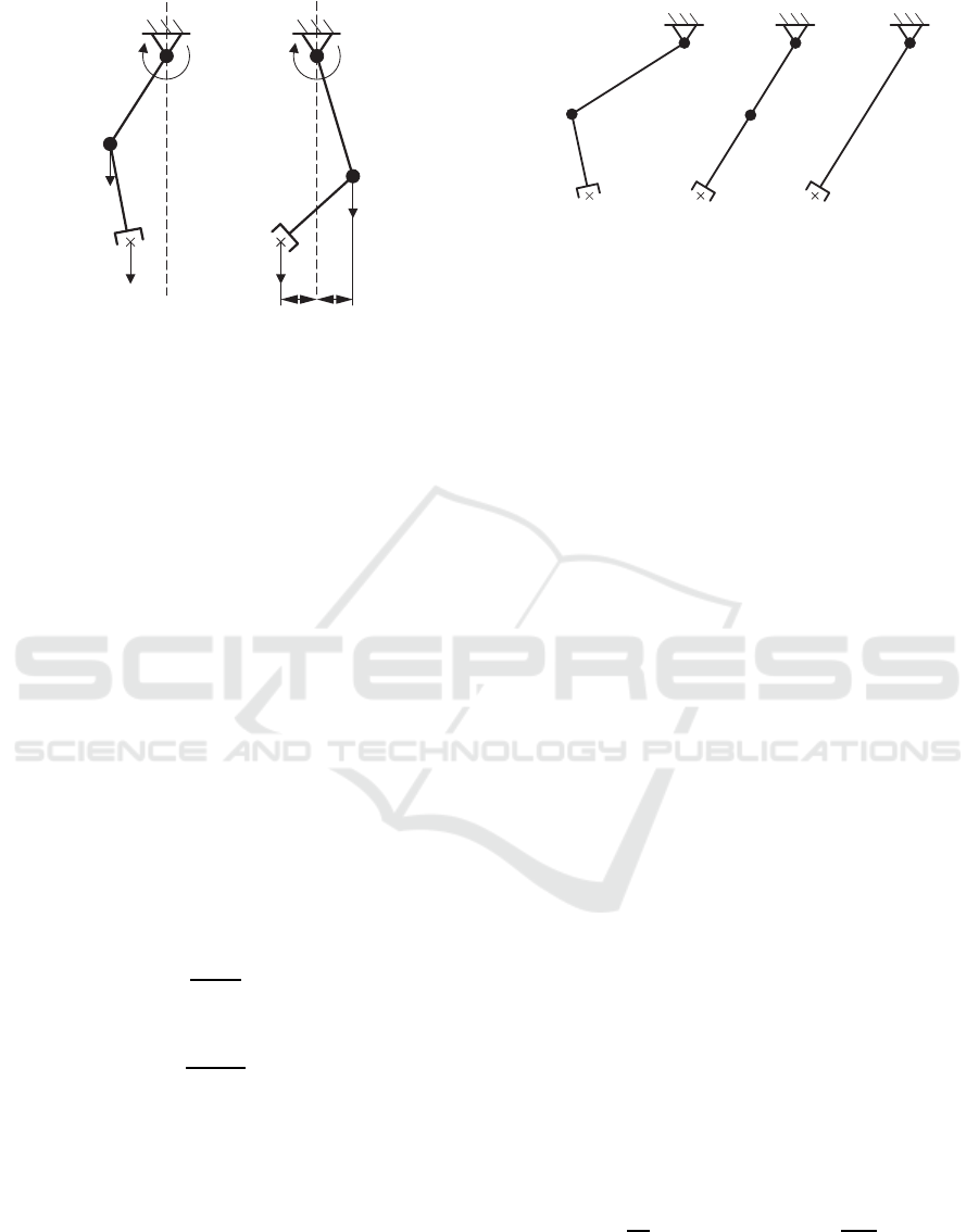
4.4.1 Effects of Term 1
The first term J
1
minimizes the motor torques of the
robot by applying a quadratic objective function. The
effects of this function on the optimization result will
be shown in a simple example, with the only goal to
minimize the torque M of the mechanical structure in
figure 8(a). The robot links are assumed massless,
thus the only relevant gravitational forces F
G
act on
joint 2 and the end-effector.
The result of the optimization is shown in figure
8(b). The algorithm changes the link length and joint
coordinates in such a way that the mass of the second
joint counter-balances the end-effector mass and the
resulting torque in joint 1 is M = 0.
Design Optimization of a Manipulator for CERN’s Future Circular Collider (FCC)
325
M
M = 0
F
G
F
G
F
G
F
G
z
z
l l
(a)
(b)
11
2
2
Figure 8: Optimization effects of J
1
.
4.4.2 Effects of Term 2
For the following example the goal was to minimize
the link lengths and the DoF of the robot, while reach-
ing the desired Cartesian position z. With the com-
mon approach to minimize parameters by using a
quadratic objective function it is possible to minimize
the link lengths of the mechanical structure shown in
figure 9(a). The result of the optimization with the
quadratic objective function is shown in figure 9(b).
It is clear that the optimization converged to an
optimum, since the links lie on a straight line from
the base to the desired end-effector position. It is also
clear that only one DoF would be sufficient to reach
this position. Thus, the quadratic objective function is
at a minimum when the total length is split up equally
over both links.
To minimize the DoF, the distance should not be
split up equally, but assigned to only one link, while
the other link length will be set to zero. The corre-
sponding joint to this link can then be removed. An
objective function f(x) which would lead to the de-
sired behavior needs to satisfy
∂f(x)
∂x
> 0 (12)
to minimize the link length and
∂
2
f(x)
∂x
2
< 0 (13)
to assign the necessary length to only one link and
thus minimize the DoF. By setting, e.g.
f(x) = arctan(x), (14)
the above requirements are satisfied. Running the
same optimization problem again with the new ob-
jective function, the summed up link length is still a
minimum and the total length is assigned to only one
link since not more than one DoF is necessary to reach
the position, see figure 9(c). Thus, the corresponding
joint i with l
i
= 0 can be removed.
l
1
l
1
l
2
l
2
l
2
z
z
z
(a)
(b)
(c)
l
1
= 0
1
1
2
2
1, 2
Figure 9: Optimization effects of J
2
.
4.4.3 Effects of Term 3
The third term J
3
of the objective function quantifies
and minimizes the error propagation in a certain di-
rection of interest. Error propagation describes how
certain errors caused by e.g. the elasticity of the gears,
backlash or control are being forwarded to the end-
effector. Looking at the mapping from joint to Carte-
sian space via the Jacobian and replacing the small
changes in joint angles ∆q with an error e, the error in
Cartesian space is
∆z
e
= J(q)e. (15)
This means that if a robot is in a singularity like
the 2-link arm in figure 9(b), the error propagation in
direction of the link is 0 and thus, the accuracy only
depends on manufacturing tolerances. As a result the
optimization algorithm will try to find configurations
for which the accuracy is less dependent on the qual-
ity of gears or control.
4.5 Model Assumptions
To simplify the optimization of the design in figure 5
and table 1 the system was reduced by omitting the
joints 11, 12 and 13 since the orientation can be de-
coupled from the positions in point 12. Thus, the vec-
tor of n
DoF
= 10 generalized coordinates used in the
optimization is
q
i
=
q
1
, q
2
, ..., q
10
T
i
. (16)
To further reduce the complexity of the optimiza-
tion problem, the linear dependent parameters l
6,7
,
l
7,8
and l
10,11
, l
11,12
are combined in new parameters
l
6,8
= l
6,7
+ l
7,8
and l
10,12
= l
10,11
+ l
11,12
. After the
optimization the lengths is split up equally such that
l
6,7
= l
7,8
=
l
6,8
2
and l
10,11
= l
11,12
=
l
10,12
2
. Thus, the
parameter vector minimizing the n
par
= 6 link lengths
is set to
p
l
=
l
4,5
, l
5,6
, l
6,8
, l
8,9
, l
9,10
, l
10,12
T
. (17)
ICINCO 2021 - 18th International Conference on Informatics in Control, Automation and Robotics
326
13
1
2
3
4
5=6
7
8=9
10
11
12
E
Figure 10: Optimized topology (DoF = 11).
Table 2: Optimized geometry.
length
[mm]
l
1,2
var.
l
2,4
288
l
4,5
927
l
5,6
0
l
6,8
754
l
8,9
0
l
9,10
635
l
10,12
518
l
12,E
100
The number of different optimization positions is set
to n
pos
= 5, as shown in section 2. The necessary mo-
tors were chosen by analyzing worst case scenarios
and the link masses per meter were designed to with-
stand these forces.
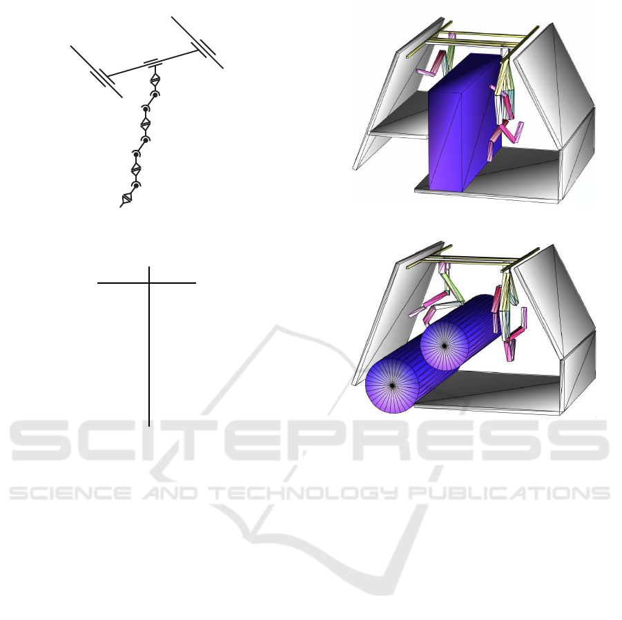
4.6 Results
The results of the design optimization are visualized
in figures 11 and 12, using the geometric primitives
described in section 4.2. The robot is visualized in all
n
pos
= 5 optimized positions with the optimal lengths
of the links. The numeric results for the parameter set
p
l
are shown in table 2. The optimal robot link lengths
l
5,6
and l
8,9
were equal to zero and thus the corre-
sponding joints can be removed and the final DoF was
reduced by 2. The resulting topology with 11 DoF is
shown in figure 10.
Matlab’s fmincon function was used as a local op-
timization solver, in this case applying the interior-
point algorithm (Byrd et al., 1999). Furthermore the
GlobalSearch or MultiStart method can be applied to
solve the global optimization problem (Ugray et al.,
2007) . In a comparison with evolutionary/genetic al-
gorithms, the GlobalSearch and MultiStart methods
lead to better results.
Figure 11: Optimization results FCC-ee (collision objects).
Figure 12: Optimization results FCC-hh (collision objects).
5 PROTOTYPE & FUTURE
WORK
Based on these findings, the first mechanical struc-
ture of the optimized design has been studied, and the
results are currently subject to integration in the tun-
nel cross-sections, within the FCC Integration Board.
For the studied scenarios, 24 of these robots will be
parked at radiation safe spots around the 100 km long
tunnel. The prototype is shown in different scenarios
in figures 14 to 15. The goal is to produce the final
version of these robots as fully customized solutions
specifically for the FCC.
For a proof of concept however, the prototype
needs to be simplified in order to reduce the effort of
building a fully customized solution. Therefor, only
the first 5 joints 1 to 6 in figure 10 (after the optimiza-
tion joint 5 is identical with joint 6) will be built in-
house and for joints 7 to 13 a 6 DoF industrial robot
will be used. This industrial manipulator has to fulfill
several requirements for seamless integration together
with the customized 5 DoF solution:
• Similar topology as joints 7 to 13 in figure 10
• Sufficient payload of at least 10 kg
Design Optimization of a Manipulator for CERN’s Future Circular Collider (FCC)
327
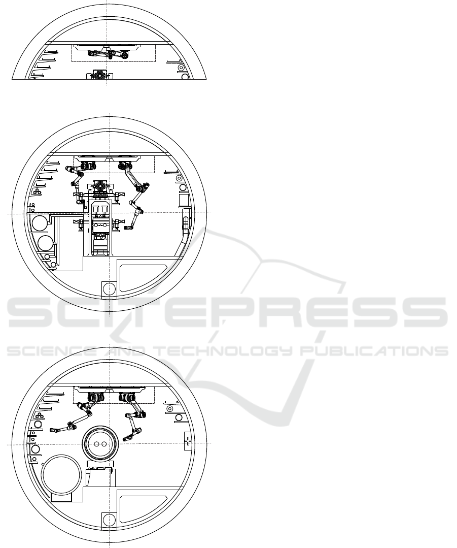
Figure 13: Prototype in FCC-ee - folded configuration.
Figure 14: Prototype in FCC-ee cross-section.
Figure 15: Prototype in FCC-hh cross-section.
• 24/48 VDC power supply
• Light weight construction with a total mass less
than 40 kg
• An open communication protocol to directly con-
trol the motors or an interface to send real-time
commands to the provided robot controller
After an extensive research, the 6 DoF collabo-
rative robot UR10e from Universal Robots A/S was
found to be the best fit for this application. The next
steps will include the design and construction of such
a prototype to show proof of concept of the most im-
portant and critical tasks in the mock-up tunnels at
CERN. The control of the highly redundant system
will be implemented in the CERN Robotic Frame-
work (CRF) (Di Castro et al., 2018), a C++ environ-
ment similar to ROS (Stanford Artificial Intelligence
Laboratory, 2018).
6 CONCLUSION
Once the objective function has been designed, the
presented design optimization delivered quantified re-
sults for a best fit robot topology with respect to all
requirements and constraints. It was possible to min-
imize the degree of freedom, the link lengths and the
torques in each joint. Thus, a optimal topology for the
manipulator in the FCC cross-sections was found.
A critical point was to satisfy the different terms
J
1
, J
2
and J
3
of the objective function. When using
different units, like mm and rad the values differed
in order of magnitudes and the function needed to be
balanced out with the weighting matrices. Further-
more having similar weights for the terms J
1
and J
3
can in some cases cause bad performance, since both
terms influence mainly the configuration of the robot.
Specifically, if the vector defining the direction of in-
terest for the manipulability measure in 10 is perpen-
dicular to the gravity vector the two terms are working
against each other. The optimization time was signifi-
cantly reduced by providing feasible sets of initial pa-
rameters, which were found by running the optimiza-
tion problem with the objective function J(x, p
l
) = 0.
Overall the results of the design optimization are sat-
isfying and fulfilled the requirements.
REFERENCES
Bestmann, P. (2008). The control of the LHC alignment
using a robot. Technical report.
Bi, Z. M. and Zhang, W. J. (2001). Concurrent optimal
design of modular robotic configuration. Journal of
Robotic Systems, 18(2):77–87.
ICINCO 2021 - 18th International Conference on Informatics in Control, Automation and Robotics
328

Byrd, R. H., Hribar, M. E., and Nocedal, J. (1999). An In-
terior Point Algorithm for Large-Scale Nonlinear Pro-
gramming. SIAM Journal on Optimization, 9(4):877–
900.
Castro, M., Tambutti, M. L. B., Gilardoni, S., Losito, R.,
Lunghi, G., and Masi, A. (2018). LHC Train Con-
trol System for Autonomous Inspections and Mea-
surements.
CDR (2019a). FCC-ee: The Lepton Collider. The European
Physical Journal Special Topics, 228(2):261–623.
CDR (2019b). FCC-hh: The Hadron Collider. The Eu-
ropean Physical Journal Special Topics, 228(4):755–
1107.
Di Castro, M., Ferre, M., and Masi, A. (2018). CERN-
TAURO: A Modular Architecture for Robotic In-
spection and Telemanipulation in Harsh and Semi-
Structured Environments. IEEE Access, 6:37506–
37522.
Gattringer, H. (2011). Starr-elastische Robotersysteme.
Springer, Berlin, Heidelberg.
Holzer, E. B., Dehning, B., Effnger, E., Emery, J., Grishin,
V., Hajdu, C., Jackson, S., Kurfuerst, C., Marsili, A.,
Misiowiec, M., Nagel, M., Busto, E. N. D., Nordt, A.,
Roderick, C., Sapinski, M., and Zamantzas, C. (2012).
Beam Loss Monitoring for LHC Machine Protection.
Physics Procedia, 37:2055–2062. Proceedings of the
2nd International Conference on Technology and In-
strumentation in Particle Physics (TIPP 2011).
M. Bajko, F. B. (2009). Report of the Task Force on the In-
cident of 19 September 2008 at the LHC. LHC Project
Report 1168.
Missiaen, D., Steinhagen, R., and Quesnel, J. (2009). The
alignment of the LHC. Technical report.
Nait-Chabane, K., Hoppenot, P., and Colle, E. (2007).
Directional Manipulability for Motion Coordination
of an Assistive Mobile Arm. In ICINCO, Angers,
France.
Stanford Artificial Intelligence Laboratory (2018). Robotic
operating system.
The MathWorks Inc. (2019). Matlab.
Ugray, Z., Lasdon, L., Plummer, J., Glover, F., Kelly, J.,
and Marti, R. (2007). Scatter Search and Local NLP
Solvers: A Multistart Framework for Global Opti-
mization. INFORMS Journal on Computing, 19:328–
340.
Valentino, G., Aßmann, R., Bruce, R., Redaelli, S., Rossi,
A., Sammut, N., and Wollmann, D. (2012). Semiau-
tomatic beam-based LHC collimator alignment. Phys.
Rev. ST Accel. Beams, 15:051002.
Van Henten, E., Van’t Slot, D., Hol, C., and Van Willigen-
burg, L. (2009). Optimal manipulator design for a cu-
cumber harvesting robot. Computers and Electronics
in Agriculture, 65(2):247–257.
Design Optimization of a Manipulator for CERN’s Future Circular Collider (FCC)
329
