
Altitude Correction of an UAV Assisted by Point Cloud Registration of
LiDAR Scans
Marcus Davi Forte
1
, Polycarpo Souza Neto
2
, George Andr
´
e Pereira Th
´
e
2
and Fabricio Gonzalez Nogueira
1
1
Department of Electrical Engineering, Federal University of Ceara, Fortaleza CEP 60455-970, Brazil
2
Department of Teleinformatic Engineering, Federal University of Ceara, Fortaleza CEP 60455-970, Brazil
Keywords:
Unmanned Aerial Vehicle, Localization, Laser Scanning, Generalized Iterative Closest Point, Fast Point
Cloud Registration, Stockpile Mapping.
Abstract:
This paper presents an online localization estimation of an Unmanned Aerial Vehicle (UAV) by fusing data
provided by the on-board flight controller and a LiDAR (Light Detection and Ranging) carried by the UAV.
Pose estimations solely obtained by the UAV are often corrupted by noise or instrumentation limitation, which
may lead to erroneous mapping of the environment. To correct potential estimation errors, the LiDAR scans
are assembled into a local point cloud history and matched against a partial map of the environment using
a proposed point cloud registration method, similar to a Simultaneous Localization and Mapping (SLAM)
approach. The resulting correction is incorporated into the estimation of the UAV using an asynchronous
Kalman Filter implementation. For this work, only the altitude errors are corrected by the registration. We
conducted tests on a local thermal power plant which contained three large coal stockpiles. We chose one of
them as our Region of Interest (ROI).
1 INTRODUCTION
The mapping procedure and modeling of three dimen-
sional objects is a subject of interest of various ap-
plications, for example precision agriculture (Lin and
Habib, 2021). The precise reconstruction of real sur-
faces has become a challenge and has been deeply
studied over last years (Vacca et al., 2018), and the
use of UAV (Unmanned Aerial Vehicle) as a remote
sensing platform has shown promising results.
It is essential that the UAV carrying sensory in-
strumentation such as cameras or Light Detection
and Ranging (LiDAR) sensors provides accurate es-
timates for its three dimensional pose. The sensory
data provided by the on-board instrumentation is usu-
ally associated to the pose of the aircraft. Any uncer-
tainty present in the pose estimation directly affects
the quality of the information inferred from the sen-
sor (Mughal et al., 2021). UAV often relies on Global
Navigation Satellite System (GNSS) combined with
Inertial Measuring Units (IMU). However, GNSS sig-
nals are vulnerable to noise and IMU is not reliable
for long-term estimations. Consequently, whenever a
GNSS signal suffers from some interference, it affect
the entire pose estimation of the UAV. A less noisy es-
timation alternative is the use of Real Time Kinematic
(RTK) equipment, which is able to offer estimations
with less than 5 cm error. Such solutions, however,
are much more expensive than GNSS solutions.
These drawback motivates the use of the on-board
instrumentation of the UAV to help correct estima-
tion errors that arise from the localization sensors.
In (Mughal et al., 2021) a deep learning technique is
used on image from cameras to localize an UAV based
on geotagged images. The approach is, however, un-
able to provide real time estimates and require train-
ing data before usage. On the other hand, LiDAR sen-
sors are able to provide common landmarks between
scans so that the motion of the aircraft is success-
fully estimated in real time, as explored in (Chiang
et al., 2017). This technique is usually integrated into
a Simultaneous Localization and Mapping (SLAM)
framework. The scan matching between frames is
achieved by applying what is known as point cloud
registration.
In this work, we will explore the use of point cloud
registration for estimating the error on the altitude of
an UAV in real time. We will present experimen-
tal results and an implementation of an asynchronous
Kalman filter for integrating the estimations.
Forte, M., Neto, P., Thé, G. and Nogueira, F.
Altitude Correction of an UAV Assisted by Point Cloud Registration of LiDAR Scans.
DOI: 10.5220/0010583004850492
In Proceedings of the 18th International Conference on Informatics in Control, Automation and Robotics (ICINCO 2021), pages 485-492
ISBN: 978-989-758-522-7
Copyright
c
2021 by SCITEPRESS – Science and Technology Publications, Lda. All rights reserved
485

2 LITERATURE REVIEW
2.1 UAV-based Laser Scanning
LiDAR based UAV scanning system is an alternative
solution to the classical photogrammetry method of
acquiring a 3D model of surfaces. The laser meth-
ods can be applied to mitigate gaps and acquire a pre-
cise point cloud image (Huang et al., 2019). It can
offer a centimeter accuracy and the data capture can
be performed either aerial or terrestrial (Amann et al.,
2001). It has been shown that such approach produces
slightly superior accuracy results comparing to pho-
togrammetry methods (He et al., 2019).
Recent works have been utilizing LiDAR sensors
to acquire 3D point clouds of bulk material stock-
piles. The works (Zhang et al., 2020; He et al., 2019)
present solutions for the laser scan measurement of
stockpiles using mobile hand-held devices that needs
to be carried along with the entire stockpile surround-
ing. This technique has the limitation that it can only
capture a side view from the stockpile, essentially
missing information about the top side of higher piles.
In addition, the data acquisition is a slow process and
can cause physical stress for the person carrying the
scanner system the whole stockpile, not to mention
that the carrier is exposed to perilous conditions dur-
ing the acquisition procedure due to the existing coal
particulates and pile collapse risk.
Equipping a similar system to a UAV overcomes
several of these difficulties. The aerial systems have
the advantage of covering large areas or places that
are not easily accessible for terrestrial systems. Some
works have successfully integrated LiDAR sensors
into UAVs in order to construct 3D point cloud data.
In (Wallace et al., 2012) a low-cost UAV-LiDAR sys-
tem was developed for managing forest inventories.
Data fusion algorithms that combine Global Position-
ing System (GPS), IMU and video camera images
are employed to UAV position and posture estimation
during the flight.
In (Beland et al., 2019) is presented the use of a
LiDAR sensor in an airborne covering large areas and
acquiring a large amount of data. Airborne LiDAR
remote sensing systems must be able to provide ac-
curate aircraft position information. Otherwise, the
formed point cloud will present unreliable informa-
tion. Measurement errors and attitude fluctuations af-
fect the accuracy of laser points, and the impacts of
these problems are discussed in (Wang et al., 2011),
(Wang et al., 2018), and (Hauser et al., 2016).
2.2 Point Cloud Registration
The Iterative Closest Point (ICP) algorithm was pro-
posed in (Besl and McKay, 1992) and aims at finding
a transformation that optimizes a rotation and trans-
lation in two point clouds. The algorithm uses one
of the data sets a reference and applies rotations and
translations to the other set. This is repeated itera-
tively until the convergence occurs, that is, the small-
est difference between the gradient of two successive
iterations. Although it is widely used in the literature,
as it has an iterative method and depends on an initial
guess, it is quite susceptible to local minimums. In
(Chen and Medioni, 1992), an improvement is made
in the ICP, where we now have information on the
surface normal, called the point to plane ICP. How-
ever, this approach fails to deal with clouds of dif-
ferent densities, with many outliers or noise, which
somehow affects the calculation of the normal.
An efficient approach to registration dense clouds
is the GICP (Segal et al., 2009). This probabilis-
tic version of the ICP is based on the probabilistic
Maximum Likelihood Estimation model (MLE). The
method explores local planar patches in both point
clouds. For this case, we say that the metric here is a
generalization of the point to point and point to plane
metrics, with the concept of plane to plane being in-
troduced. As a failure, the GICP has a reasonably
high computational cost compared to other ICP vari-
ants.
In the search for an alternative to conventional
sampling methods and the attempt to reduce ambi-
guities, computational cost and obtain better align-
ment, the Cloud Partitioning ICP (CP-ICP) method
was proposed in (Souza Neto et al., 2018). Basi-
cally, the two clouds involved in the process are parti-
tioned into the same number of slices, with each pair
(slices of the same index) subject to registration and
the best alignment among the various pairs, represents
the rigid transformation that best corrects the entire
clouds (since which are rigid bodies).
In view of the problems found in the classic al-
gorithms, sometimes the quality of the alignment, in
other situations due to the high computational cost,
this work proposes the utilization of a modified ver-
sion of CP-ICP algorithm with the purpose of correct-
ing erroneous height estimates provided by an UAV
pose estimation in real time. We will see more details
in the following section.
ICINCO 2021 - 18th International Conference on Informatics in Control, Automation and Robotics
486

3 PROPOSED MATCHING
3.1 Cloud Partitioning Generalized ICP
(CP-GICP)
Recently, it was proposed a subsampling stage of
point clouds, where two sets of data, both were par-
titioned into k parts, in order to reduce the computa-
tional cost for the alignment step.(Souza Neto et al.,
2018). This partitioning step is previous to the align-
ment, performed on the partitions by the ICP algo-
rithm (Besl and McKay, 1992). In summary, the par-
titions of the source cloud (S) are aligned with those
of the target cloud (M), where the rigid transforma-
tion that results from this alignment is replicated in
the complete source cloud, correcting its pose in rela-
tion to the reference. The equation that represents the
alignment of the partitions, using the CP-ICP method
in (Souza Neto et al., 2018) can be seen in Eq. 1.
E
j
(Ψ)
ICP
=
k
N
N
k
∑
i=1
k ~m
i
− Ψ
~
s
i
k, (1)
where j they are the indexes of the partitions being
aligned, N it is the number of points,
~
s
i
it is i-th vector
related to the source point cloud, ~m
i
the i-th vector
related to the target point cloud and Ψ it is the rigid
transformation (4 x 4 matrix) obtained from ICP in
the alignment core.
In this paper, we propose some changes to the pre-
viously mentioned algorithm, in order to adapt it to
the purpose of this work. In the current version of the
algorithm, the first modification we added a density
equalization step, as a first level of sampling. After
that, will be separate only one of the point clouds into
smaller parts hereinafter referred to as sub-clouds,
and then perform the registration process for each par-
tition with the other entire cloud, until a simple deci-
sion criterion (here the lowest possible RMSE com-
pared to a criterion decided a previously) is reached.
It is worth mentioning that this variant of the al-
gorithm with a second modification, intrinsic to the
needs of the application, where here, the alignment
core is Generalized ICP (Segal et al., 2009), suitable
for the alignment of outdoor scenarios. The equation
that describes the proposed alignment method is seen
in Eq. 2.
E
j
(Ψ)
GICP
=
k
N
N
k
∑
i=1
d
(Ψ)
T
i
(Σ
M
j
i
+ ΨΣ
S
j
i
Ψ
T
)
−1
d
(Ψ)
k
,
(2)
where d
(Ψ)
T
i
they are point to point distances of the
correspondences, Σ
S
j
i
and Σ
M
i
are covariances of the
local point neighborhoods of j-th source sub-cloud
and target point cloud, respectively.
The choice to partition only one of the clouds is
due to the size discrepancy between the data involved
in the process; in relation to the alignment core, GICP
error metric that generalizes over point to point and
point to plane, it uses covariances of the local point
neighborhoods in order to align the underlying sur-
faces rather than the points themselves (Holz et al.,
2015). The classic ICP, used in the variant improved
CP-ICP is known for its susceptibility to the problem
of local minimums. Because it is an iterative method,
it requires an initial guess, without which the algo-
rithm can easily get stuck in a local minimum (Yang
et al., 2016). If this occurs, the solution may be far
from the optimal solution, resulting in an incorrect es-
timate. This interpretation of the above can be seen in
Figure 1(a) and 1(b).
(a) (b)
Figure 1: Error metrics and transformation estimators. In
(a) point to point erro metric and (b) Generalized ICP or
plane to plane error.
3.2 Sufficient Registration
Consider two point clouds: an source point cloud and
a target point cloud. The goal is to successfully per-
form a registration procedure, which means matching
the input point cloud to the target one. Let is see the
steps:
1. Initially, we performed density equalization of the
point clouds, using a voxel grid algorithm;
2. Subdivide one of the datasets (the source) in k
sub-clouds;
3. For each of the k iterations, solve the Generalized
ICP algorithm for the partition and the entire tar-
get cloud:
• Apply the achieved transformation to the source
point cloud;
• The source cloud post GICP is then compared to
the target point cloud, using RMSE error at each
iteration;
• If the RMSE value achieved in a given iteration is
acceptable (when it compares to a stop criterion)
the algorithm stops and the ideal transformation
has been found.
Altitude Correction of an UAV Assisted by Point Cloud Registration of LiDAR Scans
487

4 LASER-BASED UAV SCANNER
SYSTEM
The aerial scanning system is mainly composed of an
industrial UAV and an embedded computer which im-
plements the proposed pose compensation system.
The DJI Matrice 100 is a fully programmable
quad-copter. It features an Onboard Software Devel-
opment Kit (OSDK) which allows sensor data sam-
pling in real-time, setting missions and waypoints,
and creating flight reports. Its weight is around 2.5
kg and can carry an additional 1.1 kg as payload.
It comes with IMU and GPS to estimate its posi-
tion and orientation. The provided SDK allows di-
rect integration with the ROS framework. Any ROS-
Supported embedded computer is able to communi-
cate with the Matrice 100 though a serial port made
available within the drone frame.
Once SDK is installed in the embedded computer,
it provides an application that offers topics contain-
ing useful information, among them, the most impor-
tant are the fused geographic coordinate and the fused
orientation data. The coordinates are the result of a
proprietary data fusion algorithm that combines data
from IMU and GPS. The resulting data is also a geo-
graphic coordinate, containing more accurate latitude,
longitude, and altitude information. Coming from the
IMU, and magnetic compass, a fused orientation is
also provided. Both 3D coordinate and 3D orienta-
tion data are published in topics with a programmable
frequency of up to 50 Hz.
The chosen embedded computer is an Asus Tinker
Board S with a Debian-based distribution which sup-
ports ROS framework. It is powered by a quad-core
ARM based processor, with 16 GB eMMC storage,
2 GB of LPDDR3 dual-channel memory, and oper-
ates at frequencies up to 1.8 GHz. Its main role is to
act as an interface between the drone and the LiDAR
sensor to assemble the point cloud data.
The used LiDAR is a SICK LD-MRS420201 de-
signed for outdoor applications. It has IP69K enclo-
sure rate protection and weights 0.77 kg. Its scanning
range stands under 150 m and 50 m for objects up
to 90% and 10% remission, respectively. And coal
is a material with low levels of remission. Therefore
the LiDAR is expected to work with a range of up to
50 m. The sensor possesses ROS drivers for integra-
tion with ROS applications, which are essential for
point cloud models assembly. The sensor is attached
beneath the drone and points towards the ground dur-
ing the flight.
5 REGISTRATION-ASSISTED
LOCALIZATION ESTIMATION
This section details the proposed system for correct-
ing measurements using point cloud registration.
The UAV is able to provide a full pose estima-
tion using inertial sensors, GNSS localization and the
model of the drone itself. As stated in the documen-
tation of the equipment, this estimation contains an
estimation error of about a few meters. We propose a
Kalman filter structure which models the noise error
and receives the correction of the point cloud registra-
tion as an update variable.
Figure 2 illustrates the estimation process. First,
the map is constructed using the pose from the UAV
instrumentation. The map construction performed
using frame transformations from an inertial frame,
whose origin is set to the take off position. and the
laser frame. As the UAV flies above the surface, the
laser point clouds are transformed to the map frame
and added to the previous ones. Notice that during
this step, it is not possible to correct the UAV pose.
As soon as the UAV detects an overlap between
the current laser scan and the map, it is assumed that
the overlap is enough to provide a correction estima-
tion. The registration process is then triggered and the
output transformation matrix is used to provide the
height correction. Subsequent laser scans are added
to the current map but with the corrected pose.
We included a parameter χ, defined as the local
point cloud history, which controls how many laser
scans are included in the source point cloud used for
the registration.
5.1 Asynchronous Kalman Filter
A Kalman filter structure is modeled to account for
the asynchronous registration corrections and the es-
timation provided by the DJI proprietary fusion so-
lution. The term asynchronous refer to that fact that
the corrections occur at a variable sampling rate, in
contrast to the predictions which occur at a constant
sampling rate. The equations remain the same, but the
implementation is slightly different. Instead of exe-
cuting both predictions and corrections in a single it-
eration, the correction step is called only upon receiv-
ing the updating states provided by the point cloud
registration. Moreover, it is possible to use multiple
corrections models, each with its own measurement
matrix and sampling rate (Shabani et al., 2015).
Since we do not have access to the UAV estima-
tion internal model, the proposed Kalman Filter treats
the incoming data from the UAV estimation as an up-
date measurement. The corresponding measurement
ICINCO 2021 - 18th International Conference on Informatics in Control, Automation and Robotics
488
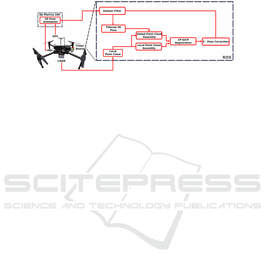
Figure 2: Flowchart of registration-assisted localization.
noise covariance is then computed through the accu-
racy given by the equipment data sheet.
The correction transformation estimation is also
treated as an update measurement. Note that the trans-
formation matrix is an 4×4 matrix, composed of a ro-
tation component and a translation component. This
work will focus only on the translational z component.
This correction is extracted from the resulting regis-
tration matrix and fed into the Kalman filter update
equation.
Therefore, the states which will be estimated by
the filter are given by
x =
x y z δz
T
, (3)
where x,y and z is the three dimensional pose of
the UAV and δz is the measurement error on z.
The Kalman Filter algorithm is implemented in
two steps, the prediction and the update. We assume
that the process and measurements noises are mod-
eled by a Gaussian distribution with zero mean. The
computation of the state prediction is given by
ˆx
−
k
= A ˆx
k−1
+ Bu, (4)
P
−
k
= AP
k−1
A
T
+ Q
n
, (5)
where x is the estimated state, A is the state transi-
tion model, B is the input model, u is the input vector,
P is the covariance of the estimation error and Q
n
is
the covariance of the process noise. The computation
of the state updates, or state innovation, is given by
˜e
k
= y
k
−C ˆx
−
k
(6)
S
k
= CP
−
k
C
T
+ R
n
(7)
K
k
= P
−
k
C
T
S
−1
(8)
ˆx = ˆx
−
k
+ K
k
˜e
k
(9)
P
k
= (I − K
k
C)P
−
k
, (10)
where ˜e
k
is the prediction error, y
k
is the measured
output, C is the output model matrix, R
n
is the mea-
surement covariance matrix and K
k
is the Kalman gain
matrix.
5.2 Implementation
Our implementation of the Kalman filter contains two
separate update steps, one from the estimated pose in-
coming from the sensory instrumentation of the UAV
and another from the registration correction. Thus,
we compose two different C matrices
C
1
=
1 0 0 0
0 1 0 0
0 0 1 −1
, (11)
which models the estimation and includes the al-
titude model error δz compensated in the measured z,
and
C
2
=
0 0 0 1
, (12)
which yields the estimated altitude error δz.
For this particular case, the prediction step (4) is
not performed. We compute only the update in the es-
timated covariance error (5) according to the noise co-
variance Q
n
which models the instrumentation noise.
This computation is calculated every time the pose is
updated.
At the same time, update equations (6)-(10) cor-
responding to C
1
is computed. This step uses its own
measurement noise covariance R
n1
.
As soon as the registration subsystem outputs its
correction estimate, the same update equations (6)-
(10) are computed, this time using the corresponding
noise R
n2
.
The measurement covariance matrix R
n1
is related
to the UAV instrumentation, while matrix R
n2
is re-
lated to the performance of the registration and how
much time has passed without any correction, since
we assume the uncertainty increases with the time.
For this work, we assume it to be a constant matrix
scaled by the time between registration corrections.
Altitude Correction of an UAV Assisted by Point Cloud Registration of LiDAR Scans
489
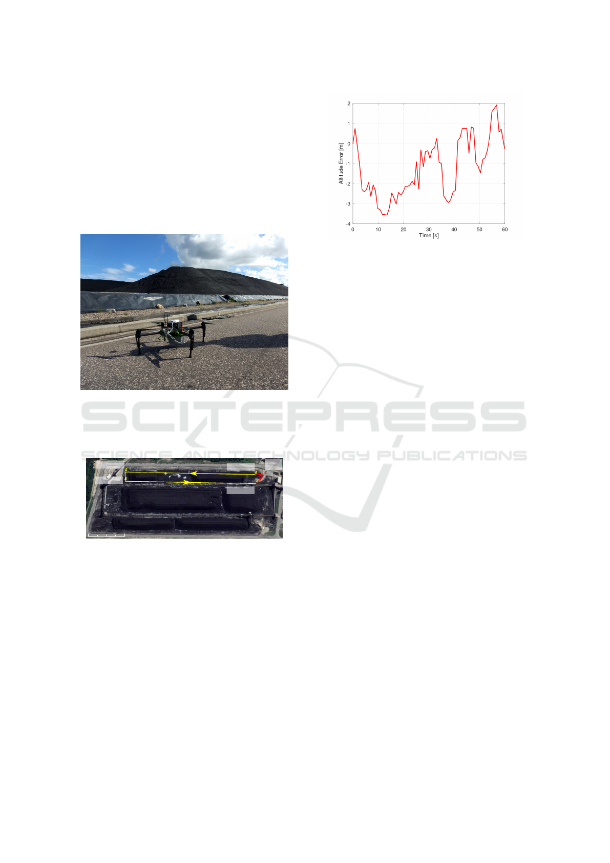
6 EXPERIMENTAL RESULTS
The developed system was evaluated through field
tests carried out in a real stockyard (Figure 3) with
a coal stock capacity of approximately 600 thousand
tons. The plant is located in the state of Cear
´
a –
Brazil and is part of the Pecem Thermoelectric Com-
plex (Pecem TC), with an installed capacity of 1080
MW of active power. There are a total of three stock-
piles within the power plant. We chose one of the for
our experiments.
Figure 3: UAV in a thermal power plant.
The UAV was programmed to fly over the chosen
stockpile by setting four waypoints to be tacked by
the flight controller, as shown in Figure 4.
150 m
Waypoint 2
Waypoint 3
Waypoint 1
Waypoint 4
Home
Point
Figure 4: Home point and waypoints used on the experi-
ments.
During the tracking of Waypoint 1 towards Way-
point 2, the UAV was set to build the map using only
the estimates from the instrumentation, without any
registration correction, since there is still no overlap-
ping region between scans and a map. During the
tracking of Waypoint 3 towards Waypoint 4, we en-
able the registration procedure. During this period,
the local point cloud history is matched against the
previously acquired map in order to estimate devia-
tion in the altitude. The correction is then applied to
the current altitude and the frame of the UAV is up-
dated. The resulting corrections are shown in Figure
5.
Notice how the altitude error varies over time and
Figure 5: Result of registration-assisted altitude correction.
may reach up to 3.5 m. The error be better visualized
in Figure 6.
6.1 Comparison between Registration
Algorithms
We implemented a variant registration approach to
CP-ICP, in C ++, with the aid of the PCL library, with-
out code optimization, and we conduct experiments of
alignment, simulating accumulation of data in three
different sizes of histories, thus comparing the pro-
posed method to CP-ICP and other classic algorithms,
focused on the alignment of outdoor scenes.
The comparison with the state of the art is car-
ried out between the point to point and point to plane
ICP variants, the Generalized ICP, CP-ICP and the
proposed method. The metrics used for comparison
are the smallest possible rotation and displacement to
be achieved, ε
R
= arccos(∆R − I)/2 (in degree) and
ε
T
= µ
c
−µ
s
(where µ
c
and µ
s
are respectively the cen-
troides of the registered source cloud and the original
source cloud) and the time (in seconds), which for ap-
plications in real time must be as small as possible.
Table 1 synthesizes the rotation, translation and
cost time performance of the various registration ap-
proaches; as it is clear from the results, the proposed
method achieved top performance for each 3D model
aligned. A good performance of the proposed ap-
proach confirms to some extent the expectations about
computational cost reduction due to partitioning and
density reduction through sampling with voxel grid,
a correct alignment by changing the alignment core,
performing small rotations, since the rotation error
here should be close to zero, in addition to a perfect
altitude correction. When compared to the others, we
conclude that the classic ICP make mistakes due to
bad estimates, as well the CP-ICP itself. Among those
used for comparison, only the GICP can achieve very
close results, however two orders of magnitude are
more costly.
ICINCO 2021 - 18th International Conference on Informatics in Control, Automation and Robotics
490
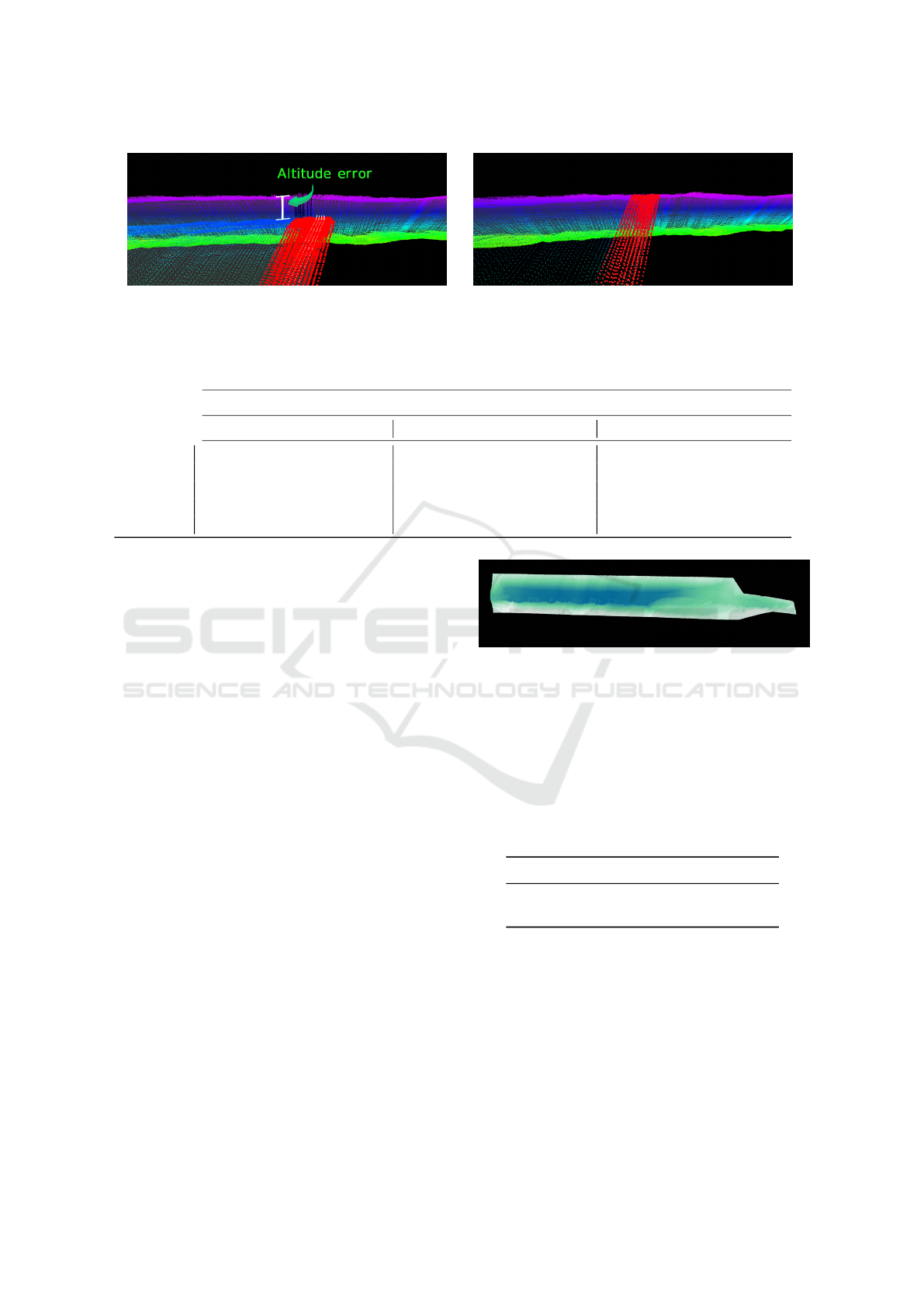
(a) (b)
Figure 6: Side view of a history registration. In (a) the initial pose, with difference in altitude and in (b) alignment with the
proposed method.
Table 1: Table with comparison metrics for the Stockpiles scenes registration.
Scan 1 Scan 2 Scan 3
ε
R
(o) ε
T
(m) t (s) ε
R
(o) ε
T
(m) t (s) ε
R
(o) ε
T
(m) t (s)
ICP
p2pt
59.1370 3.8866 6.8892 43.9945 1.2401 13.0223 42.2599 0.9203 19.2812
ICP
p2pl
50.488 4.3514 3.3678 40.0173 2.5921 5.1246 35.9679 2.4285 6.7039
GICP 0.7244 2.1613 60.1746 0.7593 1.7940 61.5916 1.2170 1.5967 70.1895
CP-ICP 27.4122 0.7217 1.4764 26.6329 -0.1478 2.8011 28.3209 -0.9307 4.1855
Proposed 0.6370 1.9936 0.5744 0.8080 1.7688 0.6042 0.2676 1.5011 0.6377
More deeply evaluating the algorithms, some fac-
tors, as the parameters set can influence. Particularly
we can mention as a factor of the choice of the GICP
instead of the ICP (for alignment core) the low tuning
sensitivity of the maximum distance for correspon-
dence. Generally, if this value is very small, the prob-
ability of convergence to an undesired local minimum
is high and the number of iterations to correct the pose
can increase. If this distance is too high, the transfor-
mation estimation may suffer with a loss of accuracy.
In the present work, our main problem is the altitude
correction, which contemplates this failure of the ICP.
In Figure 6, we have an example of a side view
of a clearly misaligned history, in 6(a), and the result
of the pose correction by the proposed algorithm, in
6(b).
6.2 Volume Estimation
Stockpile inventory control is an extremely important
process of the thermal power plant. The plant must
know how much coal they posses before issue any
purchase, selling or usage in the plant itself. The point
cloud generated by our experiments may be used to
give such important estimate. This estimate will also
be used to evaluate the performance of the mapping
and the impact caused by misaligned point clouds.
Figure 7 shows the top view of a cropped point cloud
corresponding to satellite image from Figure 4. A
ROI (Region of Interest) cropping was applied over
part of the stockpile.
Figure 7: Top View of ROI.
The volume was computed using an algorithm that
applies a gridding process and sums the volume dif-
ferences between the highest point in the cloud and an
arbitrary ground surface. We then set the same ground
plane for the resulting point clouds of the mapping
with and without registration and computed the cor-
responding volumes, as shown in Table 2.
Table 2: Estimated volumes.
Point Cloud Volume (m
3
)
Without Altitude Correction 60243.67
With Altitude Correction 54467.18
Notice that the misaligned point cloud yields a
volume error over 10%. This is a significant amount,
considering that erroneous stockpile estimates may
heavily affect the purchase and usage of the material
within the power plant.
Altitude Correction of an UAV Assisted by Point Cloud Registration of LiDAR Scans
491

7 CONCLUSION
Among the contributions of this work, we present an
approach for the registration of point cloud of external
scenarios. The proposed algorithm takes the General-
ized ICP to a new use, aligning doubly subsampled
data. In comparison with other algorithms, the low
computational cost derives from the reduction of den-
sity by the voxelgrid and the space of the sub-clouds
of one of the sets. In terms of accuracy, changing the
alignment core, using the Generalized ICP instead of
the classic ICP (as in CP-ICP), we avoid convergence
to local minimums. We then use the proposed reg-
istration approach for correcting the altitude of the
UAV in real time. The corrections allowed the sub-
sequent mapping to be aligned to the existing map,
which helps constructing a more reliable dataset that
represents the actual stockpile surface.
ACKNOWLEDGEMENTS
This study was financed in part by the Coordenac¸
˜
ao
de Aperfeic¸oamento de Pessoal de N
´
ıvel Superior-
Brazil(CAPES)-Finance Code 001; Financial support
from Energia Pecem and ANEEL under the grant
number PD-07267-0016/2018.
REFERENCES
Amann, M.-C., Bosch, T. M., Lescure, M., Myllylae, R. A.,
and Rioux, M. (2001). Laser ranging: a critical re-
view of unusual techniques for distance measurement.
Optical Engineering, 40(1):10 – 19 – 10.
Beland, M., Parker, G., Sparrow, B., Harding, D., Chas-
mer, L., Phinn, S., Antonarakis, A., and Strahler, A.
(2019). On promoting the use of LiDAR systems in
forest ecosystem research. Forest Ecology and Man-
agement, 450:117484.
Besl, P. J. and McKay, N. D. (1992). Method for registration
of 3-d shapes. IEEE Transactions on Pattern Analysis
and Machine Intelligence.
Chen, Y. and Medioni, G. (1992). Object modelling by reg-
istration of multiple range images. Image and vision
computing, 10(3):145–155.
Chiang, K., Tsai, G., Li, Y., and El-Sheimy, N. (2017). De-
velopment of LiDAR-based UAV system for environ-
ment reconstruction. IEEE Geoscience and Remote
Sensing Letters, 14(10):1790–1794.
Hauser, D., Glennie, C., and Brooks, B. (2016). Calibration
and accuracy analysis of a low-cost mapping-grade
mobile laser scanning system. Journal of Surveying
Engineering, 142(4):04016011.
He, H., Chen, T., Zeng, H., and Huang, S. (2019). Ground
control point-free unmanned aerial vehicle-based pho-
togrammetry for volume estimation of stockpiles car-
ried on barges. Sensors, 19(16):3534.
Holz, D., Ichim, A. E., Tombari, F., Rusu, R. B., and
Behnke, S. (2015). Registration with the point cloud
library: A modular framework for aligning in 3-d.
IEEE Robotics & Automation Magazine, 22(4):110–
124.
Huang, R., Jiang, L., Wang, H., and Yang, B. (2019). A
bidirectional analysis method for extracting glacier
crevasses from airborne LiDAR point clouds. Remote
Sensing, 11:2373.
Lin, Y.-C. and Habib, A. (2021). Quality control and crop
characterization framework for multi-temporal uav li-
dar data over mechanized agricultural fields. Remote
Sensing of Environment, 256:112299.
Mughal, M. H., Khokhar, M. J., and Shahzad, M. (2021).
Assisting uav localization via deep contextual image
matching. IEEE Journal of Selected Topics in Applied
Earth Observations and Remote Sensing, 14:2445–
2457.
Segal, A., Haehnel, D., and Thrun, S. (2009). Generalized-
icp. In Robotics: science and systems, volume 2, page
435.
Shabani, M., Gholami, A., and Davari, N. (2015). Asyn-
chronous direct kalman filtering approach for under-
water integrated navigation system. Nonlinear Dy-
namics, 80(1):71–85.
Souza Neto, P., Pereira, N. S., and Th
´
e, G. A. P. (2018).
Improved Cloud Partitioning Sampling for Iterative
Closest Point: Qualitative and Quantitative Compar-
ison Study. In 15th International Conference on In-
formatics in Control, Automation and Robotics.
Vacca, G., Furfaro, G., and Dessi, A. (2018). The use of the
uav images for the building 3d model generation. The
International Archives of the Photogrammetery, Re-
mote Sensing and Spatial Information Sciences, pages
217–223.
Wallace, L., Lucieer, A., Watson, C., and Turner, D. (2012).
Development of a UAV-LiDAR system with applica-
tion to forest inventory. Remote Sensing, 4(6):1519–
1543.
Wang, J., Xu, L., Fan, Y., Liu, X., Tian, Z., Wang, X.,
and Cheng, Y. (2018). A method for compensating
platform attitude fluctuation for helicopter-borne Li-
DAR: Performance and effectiveness. Measurement,
125:37–47.
Wang, J., Xu, L., Li, X., and Tian, X. (2011). Simulation
on impact of random attitude measurement errors on
point cloud and 3D image of ALS. In 2011 IEEE In-
ternational Conference on Imaging Systems and Tech-
niques, pages 60–64.
Yang, J., Li, H., Campbell, D., and Jia, Y. (2016). Go-
ICP: A Globally Optimal Solution to 3D ICP Point-
Set Registration. IEEE Transactions on Pattern Anal-
ysis and Machine Intelligence.
Zhang, W., Yang, D., Li, Y., and Xu, W. (2020). Portable
3D laser scanner for volume measurement of coal pile.
In Communication, Signal Processing, and Systems.
Lecture Notes in Electrical Engineering, volume 517,
pages 340–347.
ICINCO 2021 - 18th International Conference on Informatics in Control, Automation and Robotics
492
