
Design of a Rehabilitation Exoskeleton with Impedance Control:
First Experiments
Gaëtan Courtois
1
, Jason Chevrie
1
, Antoine Dequidt
1,2
, Xavier Bonnet
3
and Philippe Pudlo
1
1
Univ. Polytechnique Hauts-de-France, LAMIH, CNRS, UMR 8201, F-59313 Valenciennes, France
2
INSA Hauts-de-France, F-59313 Valenciennes, France
3
Institut de Biomécanique Humaine Georges Charpak, Arts et Métiers Paristech,
151 Boulevard de l'Hôpital, F-75013 Paris, France
Keywords: Lower-Limb Exoskeleton, Impedance Control, Gait Rehabilitation.
Abstract: In this paper, we disclose the design strategy, control design and preliminary works leading to the
development of a post stroke gait rehabilitation exoskeleton. The strategy is established based on the
conventional gait rehabilitation currently used in rehabilitation centers and defines the exoskeleton as an
interface between the therapist and the patient. The final purpose of this interface is to complete the
conventional rehabilitation by intensifying the work of the patient while relieving the physical burden on the
therapist. As the conventional rehabilitation is based on successive exercises the control is designed to have
several operating modes triggered depending on the currently processing exercise. A test bench was realised
to evaluate quantitatively as well as qualitatively these operating modes. Preliminary results of quantitative
experiments on the transparent operation mode are then presented. These results validate the control design
and comfort us on our development method.
1 INTRODUCTION
Today the most important cause of hemiplegia is
cerebrovascular accident or stroke. Each year around
13.7 million cases are counted in the world (Feigin
et al., 2019). Only 85% of the survivors of a stroke
can walk after 6 months. Among them 5% are said
to be severe hemiplegics and don't regain their full
autonomy (Olney et al., 1996). Then around 20% of
the survivors of a stroke never recover even if some
of them followed a rehabilitation therapy.
In this context of ever-increasing number of
people suffering from hemiplegia, due to a lack of
manpower rehabilitation centers are forced to select
the accepted patients. Hence a lot of people cannot
follow a gait rehabilitation therapy and eventually
lose their autonomy.
One of the solutions to help the therapists to
accept more patients is to propose tools like
exoskeletons to increase the chances of
rehabilitation of post stroke patients, even for the
most severe cases.
Nowadays there are numerous lower-limb
exoskeletons which are used or studied for the
rehabilitation. And even among only the
anthropomorphic ones it is still possible to find a lot
of exoskeletons used for rehabilitation (Denis et al.,
2016 and Esquenazi et al.,2017). However, this kind
of exoskeletons is not proven to improve the gait
rehabilitation compared to conventional
rehabilitation (Pennycott et al., 2012). Furthermore,
to the best of our knowledge none of them was
designed specifically for post stroke gait
rehabilitation. This way the final aim of this work is
to design an exoskeleton specifically thought for the
gait rehabilitation of hemiplegic patients.
During conventional rehabilitation post stroke
patients pass through different stages, namely
passive, semi-active and active patient. Each can be
seen as a functioning mode of the developed
exoskeleton.
Impedance control is very well-suited for the
interaction between patient and exoskeleton and is
really adaptable to these 3 phases of the
rehabilitation. Hence, in this context, impedance
control is the most appropriate for gait rehabilitation
(Akdoğan et al., 2018). Moreover, one of the most
important operating modes of rehabilitation
exoskeletons is the transparent mode (Andrade et al.,
2019) and impedance control is one of the most
suitable to achieve transparency (Tucker et al. 2015).
Courtois, G., Chevrie, J., Dequidt, A., Bonnet, X. and Pudlo, P.
Design of a Rehabilitation Exoskeleton with Impedance Control: First Experiments.
DOI: 10.5220/0010580004690476
In Proceedings of the 18th International Conference on Informatics in Control, Automation and Robotics (ICINCO 2021), pages 469-476
ISBN: 978-989-758-522-7
Copyright
c
2021 by SCITEPRESS – Science and Technology Publications, Lda. All rights reserved
469

Figure 1: Schematic representation of the rehabilitation strategy.
In this context this paper focuses on the
preliminary works on transparency made to develop
the first prototype of this exoskeleton designed for
post stroke gait rehabilitation. Section 2 displays the
elements leading to the design of a hip only actuated
exoskeleton. Section 3 details the formulation of an
hybrid impedance control law and how it applies to
transparent operation mode. Section 4 describes the
preliminary experiments on transparency made on a
test bench and shows the results. Finally, Section 5
concludes this paper and opens the way for further
developments.
2 DESIGN OF A HIP ACTUATED
EXOSKELETON
The first prototype we developed is a hip only
actuated exoskeleton. According to the therapists the
hip is indeed the most important joint to start the
rehabilitation. However, to understand the design of
this first prototype the first thing to explain is the
rehabilitation strategy.
2.1 Rehabilitation Strategy
Rehabilitation is a domain which requires
knowledge and know-how that only specialists can
show. So, we choose to work with therapists to
design the exoskeleton as a tool for the therapists
made by the therapists.
In other words, for further developments the
exoskeleton is described as an interface between the
therapist and the patient as shown in Figure 1. Its
purpose is to intensify the conventional
rehabilitation and to allow sub-acute patients to
access to the rehabilitation platforms.
2.1.1 Therapist-exoskeleton Interface
The interaction between the therapist and the
exoskeleton is made by a human-machine interface
(HMI). This interface is designed with the therapists
to make full use of their know-how thanks to the
several functionnalities available.
This HMI is designed to allow the therapist to
plan a rehabilitation session following the pattern of
the conventionnal rehabilitation. It means that the
therapist will choose exercises for the patient to
realise while assisted by the exoskeleton.
These exercises are designed by the therapists
and then translated to write the control laws. Thus
each exercise corresponds to a control with
personalized parameters. Moreover, all these
parameters can be adjusted in real time by the
therapists via the HMI.
2.1.2 Exoskeleton-patient Interface
Some choices were needed about the exoskeleton-
patient interaction to design our gait rehabilitation
exoskeleton. First, to lessen the power consumption
needed to stabilise the patients and to sustain their
weight our first choice was to use a body weight
support.
Moreover, the gait pattern has been known for
decades by the therapists and they also know that the
hip can be actuated only in the sagittal plane for the
gait rehabilitation. Then as shown in Figure 2, the
design can be simplified to put only one actuator in
this plane, which simplifies the control as well.
Figure 2: First prototype - Hip only actuated exoskeleton.
ICINCO 2021 - 18th International Conference on Informatics in Control, Automation and Robotics
470

To sum up the exoskeleton's final version's
purpose is to replace the hands of the therapist to
improve the rehabilitation of the patient while
maintaining the comfort of both of them.
2.2 Actuation Design
The actuation design regroups 3 important devices:
the servodrive, the motor and the gear. First, the
most important requirements are set as the weight
and the bulkiness of the system that need to be as
low as possible. Since the controller is used to
compensate the mechanical impedance, it is not
included in the design requirements. Thus, the
servodrive should allow implementing custom
control laws for this compensation. The controller
(Embedded PC) and the servo drive must therefore
be able to implement customized control laws for
this compensation. The servodrive must then be
configured in cyclic synchronous torque (CST)
mode and the EtherCAT fieldbus, which is widely
used in industry, is therefore particularly suitable for
ensuring controller-servodrive communication with
cycle times of less than 1 ms.
Moreover, to be freed from the problem of
homologation, all the components were picked from
supplier's catalogs to meet reliability and safety
standards (ISO 13849-1, IEC 62061).
The last important requirement that drives the
design is the torque needed for the gait
rehabilitation. The average torque needed at the hip
joint is around 1Nm normalized per patient weight
(Giovacchini et al., 2014 and Seo et al., 2016). This
way some of the already available exoskeletons can
develop more than 100 Nm at the hip to fit a large
population (Chen et al., 2019). However, due to the
bodyweight support, it was fixed with the therapists
that the max repeated torque needed can be reduced
to around 40 Nm at the hip.
Eventually at the scale of a wearable
exoskeleton, the most suitable device for the
actuation is a brushless DC motor because of its
power density (Manna et al. 2018). Then the three
devices we have chosen are a servodrive EL7411
from Beckhoff company, a BLDC motor EC 90 Flat
(+ Encoder MILE 2) from Maxon company and a
CPU-17A from HarmonicDrive company with
reduction ratio of 80:1. This actuation allows a max
repeated torque of 43Nm for a weight of 1.55kg,
which fulfills the requirement.
3 IMPEDANCE CONTROL FOR
LOWER LIMB EXOSKELETON
The hybrid impedance control law used is based on
the work of Akdogan et al. (2018). This control
appears to be well suited for the purpose of
exoskeleton assisted rehabilitation as it can be
adapted to nearly every kind of environment
(Anderson et al., 1987 and Akdogan et al., 2018).
However, as this study is about the preliminary work
of a hip only actuated exoskeleton, it is necessary to
adapt the controller used by Akdogan et al. for 3
joints upper-limb actuation to a 1 joint lower-limb
actuation.
3.1 System Dynamic Model
First, let us define the model used to describe the
system dynamics as:
τ=Iq
+F
(
q,q
)
+ G
(
q
)
−τ
,
(1)
where τ is the gear output actuation torque, q, q and
q are, respectively, the position, velocity and
acceleration of the revolute joint, I is the inertia
term, F(q,q) is the friction term, G(q) is the gravity
term and τ
is the torque resulting from the force
applied by the human limb.
3.2 Position-based Impedance Control
Applied to Lower-limb Exoskeleton
One of the components of the hybrid impedance
control law is the position-based impedance control.
This controller is mostly used to help as needed
when the patients are passive or when they don't
have too much difficulties following the desired
trajectory.
Then based on Akdogan et al. (2018) the desired
dynamic behavior written in the exoskeleton joint
space after applying the position-based impedance
control can be given as:
I
(
q
−q
)
+B
(
q −q
)
+
K
(
q−q
)
=−τ
,(2)
where I
, B
and K
are, respectively, the desired
inertia, damping and stiffness at the joint and
q
d
,q
d
and q
d
are, respectively, the desired position,
velocity and acceleration of the joint.
Still based on Akdoganet al. (2018) it is possible
to rewrite the position-based impedance control as:
Design of a Rehabilitation Exoskeleton with Impedance Control: First Experiments
471

τ=
I
I
I
q
−B
(
q −q
)
−
K
(
q−q
)
− (1+
I
I
)τ
+τ
(q,q)
,(3)
where τ
(q,q) expresses the compensation terms
depending on the system.
3.3 Force-based Impedance Control
Applied to Lower-limb Exoskeleton
It can be said that the force-based control is more
appropriate for the cases where the environment
impedance is more important than the system
impedance. As the patient represents the greater part
of the exoskeleton environment the force-based
impedance control becomes more suitable when the
rehabilitation progresses (Tucker et al. 2015).
3.3.1 Force-based Impedance Control for
Semi-active Patient
When the patient becomes more active then the
exoskeleton should be proportionally less active to
favour the patient's progress.
Then the force-based impedance control gains in
pertinence starting from the semi-active patient. This
control allows managing the start of the exercises by
perceiving the patient's intention and reacting
accordingly (this issue is beyond the scope of this
paper). Moreover, it can be used to help the patient
when this one is not able to follow the trajectory by
providing a greater torque allowing to complete the
movement. In a rehabilitation context it is more
important for the patient to finish the exercise than
perfectly following the trajectory.
The desired dynamic behavior of the joint for the
force-based impedance control inspired by Akdogan
et al. (2018) can be written as follows:
I
q +B
q −τ
=−τ
, (4)
where τ
is the desired torque applied on the limb.
Then the force-based impedance control law can be
written as follows:
τ =
(
τ
−B
q
)
−(1+
)τ
+τ
(q,q).
(5)
3.3.2 Transparent Operation Mode
Since impaired people are easier to hinder, it is then
necessary to lessen everything that can be perceived
as a burden for them (Andrade et al., 2019). The
transparency consists in minimizing the perception
of the resistance of the system. Hence, it is the first
operating mode that needs to be operational in case
of rehabilitation.
In the case of post stroke gait rehabilitation, the
transparency is mostly useful for two things. The
first one is to let the patients move their unimpaired
limb. Indeed, hemiplegia means that only one side of
the body needs rehabilitation. Then as the patients
are already weak from the stroke, the exoskeleton
should not hinder their movements.
The second one is for patients near the end of the
rehabilitation, who are more active. Then for the
rehabilitation to pursue effectively, the exoskeleton
should not assist nor hinder the patients during the
exercises.
As these two cases are mostly for active or semi-
active limbs the most appropriate control for the
transparency is the force-based impedance control
and the desired torque τ
is set to 0 for the patients
to perceive no resistance. Hence (5) becomes:
τ=−
B
q −(1+
)τ
+τ
(q,q).
(6)
Finally, this transparent operation mode is the
default mode. Otherwise, while not in transparent
operation mode nor in an exercise the exoskeleton
could be perceived as in a resistive mode. With
transparency as the default mode, the exoskeleton
can just assist as needed when it is needed.
3.4 Hybrid Impedance Control Applied
to Lower-limb Exoskeleton
In the end, the hybrid impedance control is a
combination of the previously presented control
laws. Following the same pattern as in Section3.2
and Section 3.3 the desired dynamic behavior
resulting from the combination of (2) and(4) is as
follows:
I
(
q −Sq
)
+B
(
q −Sq
)
+S
K
(
q−q
)
+(1 − S)τ
=−τ
, (7)
where S can take the value 0 and 1 to switch
between (4) and (2), respectively.
Hence the overall control law can be written as a
combination of (3) and (5) as follows:
τ=
I
I
(
SI
q
−B
(
q −Sq
)
−S
K
(
q−q
)
+
(
1−S
)
τ
)
−(1+
I
I
)τ
+τ
(
q,q
)
. (8)
ICINCO 2021 - 18th International Conference on Informatics in Control, Automation and Robotics
472
Roughly speaking, giving the value 0 or 1 to S
allows switching the control in real time and thus
adapting the comportment of the exoskeleton to assist
the patients as needed. Moreover, the three parameters
I
, B
and K
can also be modified according to the
therapist's needs to adapt to each patient.
This versatility will be useful for the chosen
rehabilitation strategy. Indeed, each exercise will
depend of the patient rehabilitation state and this
evolution of the patient also means an evolution of
the environment's impedance.
4 EXPERIMENTS AND RESULTS
This section's purpose is to display the results of
preliminary experiments. The first part is about the
test bench and the identification of its model. Then
the last two parts explain the first experiment about
transparency and the first experiment with a simple
position-based impedance control.
4.1 Test Bench
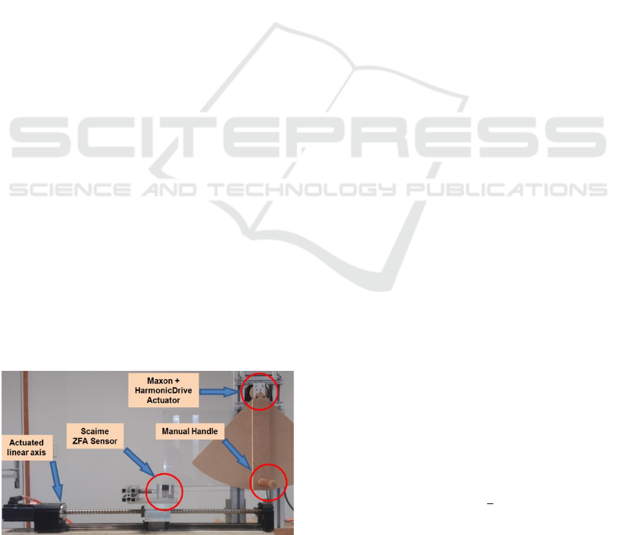
The test bench shown in Figure 3 is made using the
same actuation system described in Section 2.2. Its
purpose is to test this actuation system and the
control law.
4.1.1 Bench Description
This bench is designed to be used for qualitative
experiments with the therapists as well as for
quantitative experiments to validate the software and
the devices.
For the qualitative tests the bench is designed to
reproduce the kinematics of the hip exoskeleton
according to the features mentioned in Section 2.1.2
and to be driven with a manual handle. The human
hand being much more sensitive, it is expected that
future experiments on transparency and on the
Figure 3: Test bench for preliminary experiments.
exercises will be more conclusive. This bench
allows a wide range of tests to be carried out with
several different users, including therapists.
For the quantitative experiments the bench is
driven by a linear actuator controlled in position or
velocity to ensure the reproducibility of the protocol.
A cable wound up on a circular drum attached to the
joint is connected to the linear actuator carriage. The
tension force of the cable is measured by a
monodimensional Scaime ZFA force sensor with a
rated capacity of 25kg as shown in Figure 3. Knowing
the radius of the drum, the measured force allows
computing the torque τ
while the joint position and
velocity are derived from the servodrive's processing
of the motor's encoder signals.
4.1.2 Identification of a Compensation
Model
In order to implement the compensation term,
τ
(
q,q
)
, in the control law given in (8) an adequate
representation of the system behavior should first be
chosen and estimated. In this work, the test bench is
assumed to follow the dynamic model given in (1).
The friction term F
(
q,q
)
is chosen as a Coulomb-
viscous model, the nonlinear term G(q) accounts for
the effect of the gravity and the external torque τ
is
set to zero, such that:
τ=Iq
+F
q +F
sign
(
q
)
+ C
sin
(
q
)
,
(9)
where F
and F
are the viscous and dry friction
coefficients, respectively, C
is a gravity coefficient
and I was defined in (1).
The values of the parameters for the test bench
are identified from experimental measures using the
DIDIM algorithm (Gautier et al., 2013). A 10
seconds periodic trajectory represented as a finite
Fourier series is computed for optimal excitation of
the parameters (Swevers et al., 1997) and 25 periods
of this trajectory are applied to the system. Motor
torque measures are acquired at a sample rate of 2
kHz and the average period is computed to reduce
torque noise. The averaged samples are then filtered
by a 10.66 Hz Chebyshev filter and decimated by a
factor of 150 before being used as input for the
DIDIM algorithm. Identified values of the
parameters are given in Table 1.
The compensation term in (8) is then computed
according to:
τ
(
q,q
)
=F
q +F
tanh
+ C
sin
(
q
)
,
(10)
where the sign function in (9) is replaced by a
hyperbolic tangent function for stability purposes,
using a coefficient empirically tuned to r = 0.0375.
Design of a Rehabilitation Exoskeleton with Impedance Control: First Experiments
473

Table 1: Results of the DIDIM identification.
Parameter [unit]
Estimated value
(relative standar
d
deviation)
C
[N.m]
2.000 (6.06%)
F
[N.m.s/°]
5.584 10
(5.26%)
F
[N.m] 2.602 (2.21%)
I [kg.m²] 2.042 (3.31%)
4.2 Transparent Operation Mode:
Preliminary Experiment
Knowing a model of the test bench, this section
presents a first experiment to validate quantitatively
the effect of the transparent operation mode. For this
purpose, an experimental protocol was followed on
the test bench.
4.2.1 Protocol
For the transparency, the control law is force-based
as shown in (6). However, without a closed-loop in
force τ
=0 and I
is set to I and B
to 0. The
implemented control law thus becomes:
τ = τ
(
q,q
)
. (11)
The experiment consists of 20 successive
trajectories at constant velocities between 10°/s and
30°/s. This way a curve can be drawn to display the
evolution of the torque depending on the velocity.
Thus, the comparison between the curves with and
without compensation can show the effect of the
transparent operation mode.
4.2.2 Results
The results of this first experiment are displayed in
Figure 4. The blue points are the average torque
without compensation and the red ones represent the
average torque with the compensation for the same
velocity values.
Figure 4: Comparison of the average torque needed for
several velocities with and without compensation.
As anticipated the average torque measured with
the compensation is quasi constant and very close to
0. These results show that this model can achieve
transparency.
However, this diagram shows that the
transparency can be improved. Even if the torque
should not reach 0, for stability purposes, it seems
possible to adjust the parameters to move closer to 0.
Furthermore (6) is not fully exploited. Hence, these
results are quite encouraging for further
developments about the transparent operation mode.
4.3 Position-based Impedance Control:
Preliminary Experiment
This second experiment is presented to test the
identified compensation model while applying a
position-based impedance control. The purpose of
this experiment is to compare the behavior of the
system with and without the compensation.
4.3.1 Protocol
In this experiment the control law (3) is used with
I
=I, q
=0, B
=0 and without closed-loop in
force so τ
=0. This way it applies a constant
stiffness mimicking a spring and can be written as
follows:
τ=−
K
(q − q
)+τ
(q,q), (12)
where q
= −45° is the initial angular position of
the handle and K
= 0.3686Nm/° is the stiffness of
the virtual spring attached to q
.
The experiment consists of 20 successive round
trips of the linear actuator between -45° and 35° of
the handle. The velocity is maintained during all the
successive experiments at a constant value of
20.25°/s (seen at the handle). This way the measures
allow the comparison of the system's response with
and without the compensation.
4.3.2 Results
The results of this second experiment are shown in
Figure 5. In green is displayed the theoretical value
of the torque given by the virtual spring. The blue
curve displays the torque of the average cycle
without the compensation and the red one with the
compensation.
First of all, the compensation shows clearly its
effects during the going part. In this part of the cycle
the compensation corresponds to the expectations
based on the results in Section4.2.2.
ICINCO 2021 - 18th International Conference on Informatics in Control, Automation and Robotics
474
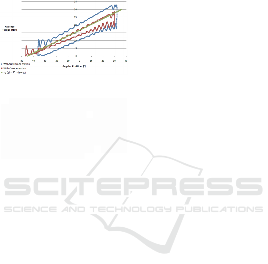
Figure 5: Comparison of the average torque with and
without compensation while applying a compliance τ
(q).
Two other details are also noticeable. The first
one is the presence of the oscillations seen during
the transient phases. (Knowing that B
= 0 this could
be expected.) In practice, these disturbances are not
desired for future applications. However, it should
not be forgotten that the control law used in this
preliminary experiment is not the full one as shown
in (3) so the other terms, especially B
, could be
used to attenuate these oscillations.
The second and the most important issue on this
diagram is the non symmetry of the red curve around
the green one. This non symmetry shows the limit of
our test bench which is quite usable for this
preliminary experiment but lacks some precision in
the metrology.
5 CONCLUSIONS
The developments to achieve the first prototype of
this gait rehabilitation-oriented exoskeleton are near
to the end and the results of the preliminary tests are
encouraging. Currently the expectations were met
even if the results showed some of the test bench
limits.
For the next developments the first thing to do
will be to optimise the test bench to be able to apply
the full control law.
In a second time it is planned to implement a
disturbance observer to estimate the interactive force
between the patient and the exoskeleton. Therefore,
it will be possible to analyze some robust control
schemes with force closed loop.
These two points will allow us to implement the
overall control law and test it quantitatively on the
test bench. Furthermore, it will also be possible to
qualitatively test it with the manual handle to
improve the perception according to the therapists'
feedback.
ACKNOWLEGEMENTS
This work was supported by the Carnot ARTS
Institute in the framework of RehaByEXO project
and the Région Hauts-de-France.
The authors gratefully acknowledge the support
of these institutions.
REFERENCES
Anderson R., Spong M., 1987, "Hybrid impedance control
of robotic manipulators", Proceedings. IEEE
International Conference on Robotics and Automation.
Andrade R. et al., 2019, "Development of a “transparent
operation mode” for a lower-limb exoskeleton
designed for children with cerebral palsy", 16th
International Conference on Rehabilitation Robotics.
Akdoğan E. et al., 2018, " Hybrid impedance control of a
robot manipulator for wrist and forearm rehabilitation:
Performance analysis and clinical results",
Mechatronics, Vol.49, P. 77-91.
Chen B. et al., 2019,"Knee exoskeletons for gait
rehabilitation and human performance augmentation:
A state-of-the-art», Mecanism and machine theory.
Denis L. et al., 2016,"Powered robotic exoskeletons in
poststroke rehabilitation of gait: a scoping review",
Journal of NeuroEngineering and Rehabilitation
13:53.
Esquenazi A. et al., 2017, "Powered Exoskeletons for
Walking Assistance in Persons with Central Nervous
System Injuries: A Narrative Review", American
academy of physical medicine & rehabilitation,
PM&R 9, P. 46-62.
Feigin V. et al., 2019, " Global, regional, and national
burden of stroke, 1990–2016: a systematic analysis for
the Global Burden of Disease Study 2016», The
Lancet Neurology, Vol. 18, No. 5,P. 439-458.
Gautier M & al., 2013, "A New Closed-Loop Output Error
Method for Parameter Identification of Robot
Dynamics », IEEE Transactions on Control Systems
Technology, Vol. 21, No. 2, P. 428-444.
Giovacchini F. et al., 2014, "A light-weight active orthosis
for hip movement assistance", Robotics and
autonomous system.
Manna S. et al., 2018, "Comparative study of actuation
systems for portable upper limb exoskeletons",
Medical Engineering & Physics.
Olney S. et al., 1996, "Hemiparetic gait following stroke.
Part I: Characteristics", Gait and posture, Vol. 4, P.
136-148.
Pennycott A. et al., 2012, "Towards more effective robotic
gait training for stroke rehabilitation: a review",
Journal of Neuro Engineering and Rehabilitation.
Seo K. et al., 2016, "Fully Autonomous Hip Exoskeleton
Saves Metabolic Cost of Walking», IEEE International
Conference on Robotics and Automation (ICRA).
Design of a Rehabilitation Exoskeleton with Impedance Control: First Experiments
475

Swevers J. & al., 1997, "Optimal robot excitation and
identification", IEEE Transactions on Robotics and
Automation, Vol. 13, No. 5, P. 730‑740.
Tucker M. et al., 2015, "Control strategies for active lower
extremity prosthetics and orthotics: a review», Journal
of Neuro Engineering and Rehabilitation, 12:1.
ICINCO 2021 - 18th International Conference on Informatics in Control, Automation and Robotics
476
