
A Distributed Mesh Generation Study Case through a Customizable
Platform as a Service Framework
Francesc Costa-Maj
´
o
1
, Paloma Barreda
2
and Sergio Iserte
2 a
1
Universitat Oberta de Catalunya (UOC), Spain
2
Universitat Jaume I (UJI), Spain
Keywords:
Meshing, OpenFoam, Paraview, Distributed Computing, Cloud Computing.
Abstract:
The quality of a mesh can determine the accuracy of a Computational Fluid Dynamics (CFD) simulation. In
fact, meshing is not only a user highly time-consuming endeavor but also demands a lot of computational
power. The need for powerful and useful tools for meshing can have a real impact on productivity and the
final result. In this paper, a customizable platform as a service for meshing, named Evoker, is presented and
evaluated to assist users to work over different types of geometries and accelerate the generation of meshes.
Evoker is a zero-installation tool with a web Graphical User Interface (Web-GUI), which cloud-server runs
OpenFOAM in order to provide a friendly interface to its meshing utilities. Evoker also manages cloud
computing resources to distribute the mesh generation among different processors. Through the presented
use case, Evoker demonstrates to be a versatile meshing solution that can help to save a lot of time for their
users.
1 INTRODUCTION
CFD simulations are considered the preferred tool
for modeling fluid flows in physical domains. CFD
is based on numerical methods which provide a
high level of accuracy in their calculations of
the fluid flows. CFD is highly widespread in
research as well as in engineering. For instance, in
fields such as environment (Climent et al., 2018),
biology (W
¨
ustenhagen et al., 2021), aerodynamics (Li
et al., 2012), weather forecast (Zajaczkowski et al.,
2011), heat transfer (Jayakumar et al., 2008), or
combustion (Norton and Vlachos, 2003).
The volume used by the fluid is discretized
into cells that composed the mesh. This volume
discretization is not only a computationally expensive
process but also meticulous work for the engineer in
charge. Furthermore, the accuracy of the numerical
solution depends on the quality of the computational
mesh. For this reason, tools that facilitate the
meshing tuning process and provide mechanisms for
accelerating the generation of meshes, are crucial.
Commonly, the use of CFD methodology is
divided into three parts: preprocessing, simulation,
and postprocessing. It is during the preprocessing
a
https://orcid.org/0000-0003-3654-7924
where the mesh is defined. Concretely, this stage
begins with the definition of the physical bound of the
problem with a CAD geometry. Through surfaces and
boundaries identification in the geometry, the volume
can be appropriately discretized into a mesh. Before
starting the simulation, fluid motion equations and
boundaries conditions have to be determined.
Although many CFD software can be found in
the market, OpenFoam is ubiquitous in most areas
of engineering and science, in both industry and
academia. OpenFoam is open source and provides a
vast range of features to solve most of the complex
fluids flows.
However, limitations such as the long learning
curve that generalist CFD software implies, may
prevent further extending the CFD usage in some
disciplines or organizations. For example, since
the adoption of CFD modeling in the wastewater
treatment field, scientific production has increased.
In this regard, one of the main reasons that prevent
the ubiquitous presence of CFD in this sector is its
shallow learning curve (Glover et al., 2006).
Web-based simulation platforms aim to provide
easy-to-use interfaces for the implantation of CFD
technologies leveraging Platform as a Service (PaaS)
techniques on cloud computing environments. In an
effort to shorten the learning curve, some platforms
414
Costa-Majó, F., Barreda, P. and Iserte, S.
A Distributed Mesh Generation Study Case through a Customizable Platform as a Service Framework.
DOI: 10.5220/0010576904140421
In Proceedings of the 11th International Conference on Simulation and Modeling Methodologies, Technologies and Applications (SIMULTECH 2021), pages 414-421
ISBN: 978-989-758-528-9
Copyright
c
2021 by SCITEPRESS – Science and Technology Publications, Lda. All rights reserved

narrow this scope and they keep focused on a
certain type of fluid simulations, for example, wind,
combustion, blood vessels, etc. With this approach,
users are not expected to know all the features, but
only the very specifics of their field.
Following the philosophy of focusing tools on
particular problems, this paper analyses a use
case of meshing a Secondary Settling Tank (SST),
commonly found in Water Resource Recovery
Facilities (WRRF), with a tool tailored for this
purpose. The software, named Evoker, provides an
online GUI, is open-source, and can be installed in a
public or private cloud. This paper presents Evoker
as a scientific visualizer and mesh generator that
harnesses the Visualization Toolkit (VTK) to render
and display, and OpenFOAM capable to discretize
complex 2D and 3D domains into meshes of high
quality. Furthermore, Evoker is highly scalable
capable of leveraging multi-core environments and
distributed computing.
The rest of the paper is structure as follows:
Section 2 describes related technologies and
solutions. Section 3 introduces the meshing platform
and its features. Section 4 presents a realistic
use case to evaluate usability and performance.
Finally, Section 5 summarizes the conclusions, while
Section 6 explores open branches of research related
to this work.
2 BACKGROUND
From the usability point of view of meshing, the
current trends of software aim towards web-based
GUIs, cloud services, and parallel execution.
Desktop applications are left behind in favor of
“unlimited” computational power, and forgetting
hardware/software requirements in on-premise
facilities.
Following, some of the most interesting platforms
with support for meshing are introduced:
• OpenFoam
1
: the role model of open-source
CFD software, the official version does not
have a GUI, and it is intended to be executed
on-premises (Weller et al., 1998).
• Ansys Fluent
2
: widely used in industry, provide a
desktop GUI for on-premises execution. A license
is required to use it.
• SimFlow
3
: provides a desktop GUI for
1
https://openfoam.com
2
https://www.ansys.com/products/fluids/ansys-fluent
3
https://sim-flow.com
OpenFoam. The full version requires the
payment of a license.
• Gmsh
4
: a three-dimensional finite element mesh
generator with GUI for desktop (Geuzaine and
Remacle, 2009).
• UberCloud
5
: enables pay-per-use
high-performance cloud computing in any
CFD software. Users can use their preferred
desktop GUI (bring-your-own-licence) and
offload the computation to the cloud.
• SimScale
6
: holistic cloud-based simulation
software, from preprocessing to postprocessing
through simulation. The full version requires the
payment of a license.
• Ingrid Cloud
7
: cloud-based CFD software
specialized in wind simulations. The full version
requires the payment of a license.
• TransAT
8
: is a versatile fluid-flow simulation
and multi-dimensional meshing platform (it needs
a license). Furthermore, in (Taylor et al.,
2018), TransAT is included in CloudSME
9
, a
PaaS that brings together workflow services
and multi-cloud deployment for commercial
applications. The commercial nature of this
solution has prevented authors to evaluate it.
Despite the big variety of alternatives for meshing, in
most cases, their broad scope makes that using them
in a particular domain poses a non-assumable cost
when going along the learning curve. Furthermore,
desktop versions may not be scalable enough when
it comes to large 3D structures. For this reason, it is
crucial to count on cloud-ready software that can be
adapted to the real specific necessities.
This paper evaluates the mesh generation case
of a WRRF circular SST with a customized PaaS
solution, named Evoker. Particularly, it counts
with a web-based GUI capable of leveraging the
computational power of the cloud. This platform
enables the interaction of these two frameworks:
• On the one hand, OpenFoam provides the
meshing engine. Among others advantages,
OpenFoam is open-source and it does not need
a license to operate; it has a large community
of users that test and report many features
and issues; and it is implemented with the
Message Passing Interface (MPI) (MPI-Forum,
4
https://gmsh.info
5
https://www.theubercloud.com
6
https://www.simscale.com
7
https://www.ingridcloud.com
8
https://transat-cfd.com
9
https://cloudsme.eu
A Distributed Mesh Generation Study Case through a Customizable Platform as a Service Framework
415
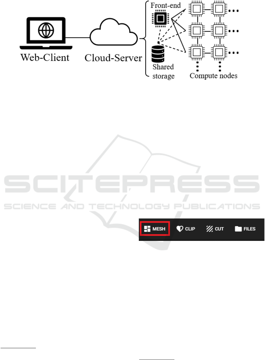
Figure 1: Evoker architecture scheme.
1994) enabling native support for distributed
computing, fostering scalable execution.
Concretely, OpenFoam leverages the blockMesh
command to decompose the domain geometry
with hexahedral blocks. Furthermore, with the
snappyHexMesh utility, OpenFOAM generates
3D meshes of split-hexahedra automatically from
triangulated surface geometries, or tri-surfaces, in
Stereolithography
10
(STL) format.
• On the other hand, Paraview (Ayachit, 2015)
allows the efficient building of complex
scientific visualizations. Paraview is open-source
and leverages the VTK API (Schroeder and
Lorensen, 2006) in order to provide the necessary
visualization and analysis features. It is designed
to be scalable on parallel architectures, leveraging
shared, as well as, distributed memory systems.
Paraview has a client-server architecture to
facilitate remote visualization of datasets.
Particularly, with Paraview Lite
11
the client can
be executed in a web-based GUI delegating the
rendering to a remote server. In this regard, the
client does not need high-performance hardware
since the render is performed externally, desirably
in a large computing facility.
3 EVOKER
This paper presents Evoker, a PaaS solution for
automating the process of creating models for finite
element analysis. The platform provides a mesh
generation interface to OpenFOAM that supports
projects with defined surfaces in STL format.
These surfaces can be created with software such as
10
https://www.loc.gov/preservation/digital/formats/fdd/
fdd000506
11
https://kitware.github.io/paraview-lite
SolidWorks
12
or HydroSludge (Climent et al.,
2019). The surfaces will determine the refinement
areas where the mesh can have a finer grain.
Evoker is based on a zero-installation client-server
architecture and aims to provide a cloud platform
for deploying fully customizable scalable meshing
solutions. Figure 1 depicts the scheme of the
platform.
On the client-side, Evoker is available via a
web-GUI from a computer or smartphone, from their
devices to the server hosted in the cloud. The
client runs Paraview Lite, which establishes the
connection with Paraview on the server. Paraview
Lite, by default, is presented with visualization tools
such as clip, cut, or stream lines. Evoker adds
to this interface the tab Mesh, which includes the
configurable parameters for meshing (see Figure 2).
Figure 2: Evoker menu tabs.
The server is responsible for orchestrating the
execution of OpenFOAM’s methods, in accordance
with user requirements. The mesh is generated
leveraging the commands blockMesh and
snappyHexMesh, properly configured. Furthermore,
when users enable parallel computing, Evoker
server also manages the methods to divide and
join the domain, respectively decomposePar and
reconstructPar.
The server-side is deployed in the cloud
computing provider infrastructure and it is composed
of a cluster of nodes. Figure 1 illustrates the structure
of the cluster composed of two different types of
actors: front-end and computes.
The front-end accepts users’ connections as well
12
https://www.solidworks.com
SIMULTECH 2021 - 11th International Conference on Simulation and Modeling Methodologies, Technologies and Applications
416
Inlet
SFango
SAguaClar
Campana
Sup Libre
Clarified water
External
recycling
Feed well
Inlet
Free surface
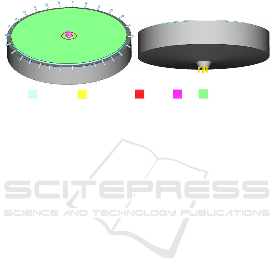
Figure 3: Scheme of the in/out flows and the geometry of the circular SST under study.
as renders the scientific visualizations. The front-end
runs the Paraview server and parses the meshing
parameters to OpenFOAM files. The front-end also
initiates the mesh generation process on the compute
nodes. Depending on the PaaS configuration, the
quantity of available compute nodes varies. However,
it is designed to scale up or down depending
on the computational power requirements. The
compute nodes are Evoker’s workforce. Thanks to
the parallel implementation of OpenFOAM, using
the Message Passing Interface (MPI), these nodes
can calculate concurrently sub-domains of the main
domain. Moreover, multi-processor nodes can work
on more than one sub-domain, increasing the level of
parallelism.
The distributed approach, not only allows to scale
up the number of processes, but also, the problem
size, or in other words, the number of cells composing
a mesh. In this regard, the mesh size is not limited by
the available RAM in the machine, but by the cluster
accumulated memory, which in turn, can be expanded
by adding more nodes.
Although the virtual machines in the cluster are
equipped with local storage, in order to reduce
communications, all the nodes in the cluster, have
access to shared storage. In this regard, once the
project is loaded, the front-end, as well as, the
compute nodes are able to use the data without further
explicit data transfers.
Depending on the underlying cloud provider, the
server-side computational power and its economical
cost can be adapted to the specific user necessities.
4 RESULTS
In this section, a practical example is presented and
used as a study case. Firstly, Evoker’s configuration
for this case is described. Secondly, the testbed
is introduced and evaluated to determine the most
appropriate parallel execution configuration. Finally,
this section ends with a detailed description of the
meshing experiments carried out.
The meshing study case is based on a circular
settling tank with a diameter of 18.5 meters and 5.5
meters in height. Figure 3 shows the structure of
this tank, which is further detailed in Section 4.3.
SSTs are an essential component of WRRFs.
Since many circular SSTs share the same set of
characteristics –with different dimensions or little
structural variations–, this type of object is a suitable
candidate for leveraging Evoker.
4.1 Evoker Configuration
Taking into account the characteristics of the structure
under study, when configuring the meshing platform,
the following two sets of parameters have been
defined:
• User Defined. The web-GUI displays the knobs
for determining the size of the cells, and the
minimum-maximum refinements levels of the
mesh surfaces (see Figure 4). Although by
default, the mesh generation is launched as a serial
procedure, at the bottom of the configuration
panel, the user is allowed to specify the desired
distributed topology of processors for parallel
computing.
• Implicit Configuration. During the mesh
generation operation the OpenFOAM command
A Distributed Mesh Generation Study Case through a Customizable Platform as a Service Framework
417
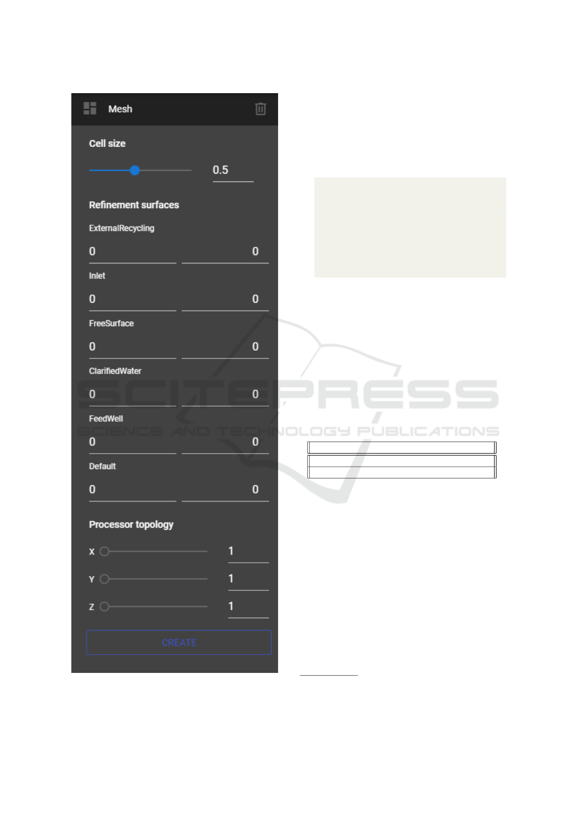
Figure 4: User defined parameters panel.
snappyHexMesh is executed. Particularly,
Evoker server has been configured to enable
castellatedMesh and snap methods. While
the castellation task takes the refinement
configuration from the user defined parameters;
when snapping, the following controls have been
defined in the snappyHexMeshDict file:
1 s na p C on t r ol s {
2 nS m o ot h P at c h 3;
3 to l er a nc e 1;
4 nS o lv e Ite r 30 0;
5 nR e la x Ite r 5;
6 n Fe a t ur e S n ap I t er 1 0;
7 i mp l i c it F e a tu r e S na p tr ue ;
8 e xp l i c it F e a tu r e S na p f al se ;
9 }
4.2 Performance Analysis
In this study, Evoker has been deployed on Eds
v4 series virtual machines from Microsoft Azure
13
.
These instances are equipped with the Intel® Xeon®
Platinum 8272CL processor. This custom processor
runs at a base speed of 2.5 Ghz and can achieve up
to 3.4 Ghz. Table 1 shows the specifications of the
instances used in this study at the moment of writing
this paper (Azure, 2021a) based on Linux CentOS in
Switzerland North region.
Table 1: Eds v4 (latest generation) instances specs.
Type vCPUs RAM Pay as you go
E4ds 4 32 GiB $0.432/hour
E16ds 16 128 GiB $1.728/hour
Evoker server, because of its distributed nature,
runs in a cluster composed of a front-end and
compute nodes. Those roles have different computing
necessities. On the one hand, the front-end is
responsible for allowing clients connections and
rendering the meshes. For this reason, a virtual
machine with an E16ds instance type has been chosen
due to its memory capacity and the number of
processors, which allow providing renders to the
client with low latency. On the other hand, compute
nodes are in charge of generating the meshes. Since
the mesh generation operation is distributed, the
number of compute nodes can be adjusted to the
problem size. In this regard, a smaller instance type
(E4ds) has been selected to conform to the compute
cluster.
13
https://azure.microsoft.com
SIMULTECH 2021 - 11th International Conference on Simulation and Modeling Methodologies, Technologies and Applications
418
The server side counts with a serverless file
system shared along with the cluster. For
this reason, a tier Premium FileStorage account
with locally-redunant storage replication policy,
is leveraged. The Premium file shares are
offered on high-performance solid-state drive based
storage (Azure, 2021b).
To determine the process layout that reaches the
maximum performance, a strong scalability analysis
is carried out. For this purpose, the execution
time of a fixed problem size is evaluated with a
different number of process configurations. Speedup
(see Equation 1) has been used as the measure to
determine the relative performance of a given parallel
configuration (many processes) compared to the serial
execution (one process). Speedup is defined as
S =
T
serial
T
parallel
, (1)
where S is the number of times that the execution time
is reduced from the serial configuration execution
time (T
serial
). And T
parallel
is the execution time of
a particular parallel configuration. The speedup is
inversely proportional to the execution time.
The target problem size of this evaluation is a
domain of dimensions 185× 55× 185, in the X, Y, and
Z coordinates respectively, for a total of 1.882.375
cells.
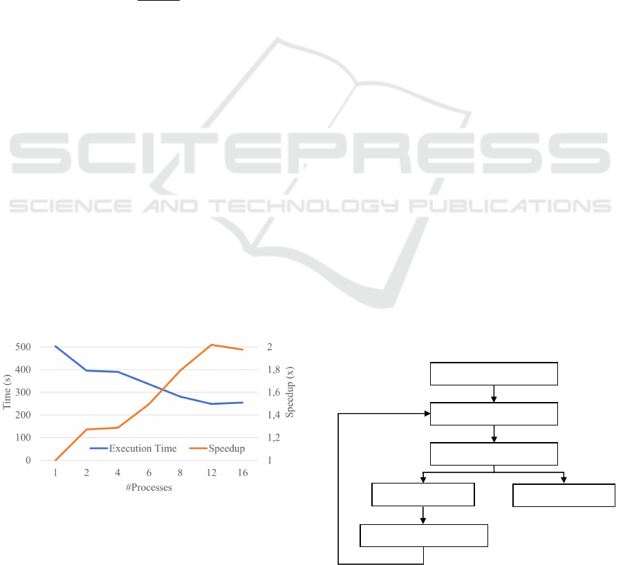
Figure 5 compares the execution time and speedup
of each process configuration. The figure shows
that the maximum performance is achieved using
12 processes, where the speedup stops increasing
(likewise, the execution time does not longer
decrease). This configuration is executed using three
nodes and four processes per node. Furthermore,
using this process configuration, the domain has
been divided into 12 sub-domains with the topology
coordinates (X, Y, Z): 6 × 1 × 2.
Figure 5: Scalability analysis.
Figure 5 also depicts that increasing the number of
resources, from three (12 processors) to four (16
processors) nodes, does not pose a further decrease
in the execution time. In fact, the communication
overhead within the four nodes, together with
the overlapping access to the shared storage, are
counterproductive in terms of performance.
4.3 Evaluation
This evaluation is composed of the definition of
the experimental scheme, and how the meshing is
configured.
The structure under study has some areas of
special interest, which have to show a higher level
of refinement in order to allow the CFD to operate
more accurate calculations. These areas are defined
as surfaces. Concretely, this circular SST has an
influent flow, two different outflows, an external
recycling, and a clarified water outlet. Besides, there
is also a free surface on top of the clarifier (it is
in direct contact with the air); and the feed well
surface which has been established to be able to refine
the cells around it and have detailed information
of the hydrodynamics (since the largest velocities
fluctuations in the fluid simulation of the model take
place there). These surfaces and their locations on the
model are shown in Figure 3. The rest of the areas
that were not designated when creating the geometry
make up the remaining surface called “Default”.
The experimental method is initiated by
establishing a cell size. Without any further
refinements, the goodness of the fit is checked by
analyzing the most critical areas and, subsequently,
a refinement is performed to see if a good meshing
quality can be obtained in those surfaces. If the
mesh has irregular nodes or areas with insufficient
nodes, another cell size is set to match the desired
characteristics.
Figure 6 depicts the scheme of the iterative
methodology used for the meshing evaluation with
Evoker. It is beyond the scope of this paper to discuss
other more complex mesh evaluation methods.
Establish cell size
Analyze surfaces
Refinement of surfaces
Poor mesh quality
Good mesh quality
Modify cell size
Figure 6: General scheme for the design of the mesh.
A Distributed Mesh Generation Study Case through a Customizable Platform as a Service Framework
419
In this study, the inlet, feed well, and external
recycling surfaces are considered the most critical
surfaces since they are the in/outflow areas or are near
them. For this reason, a non-acceptable mesh quality
may be translated into an incorrect afterward CFD
simulation. Contrariwise, at the clarified water outlet
no refinement is considered necessary since the water
outlet speeds are expected to be very low.
Therefore, it is considered that with a cell size of
0.2 meters or lower there may be enough nodes to
obtain accurate results. Thus, using a trial-and-error
approach, the fine-tuning of the critical surfaces is set
to a minimum of one level and a maximum of two
levels of refinement.
The first mesh attempt made for a cell size of 0.2
meters (with its consequent refinements) resulted in
an unsuitable quality mesh. Figure 7 shows some
examples found of aspects that make up a poor
quality mesh. For instance, the irregular nodes across
the inner surface of the clarifier (left), may lead to
errors during the CFD resolution. Besides, at the
boundaries of the inlet and feed well surfaces (right)
the refinements applied are not enough as the nodes
around them differ in number and shape. Hence, the
cell size must be reduced to obtain a better adaptation
of the mesh in those areas.
Figure 7: Examples of poor quality meshes obtained for the
SST study case.
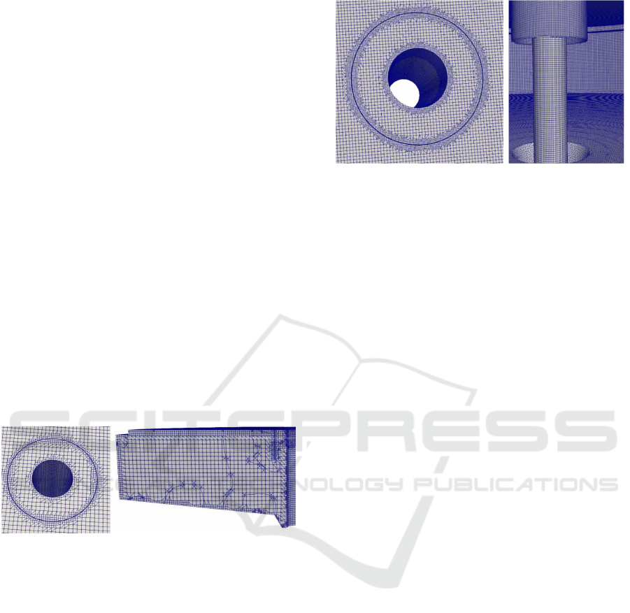
Finally, after a couple of iterations, a good quality
mesh is obtained with a cell size of 0.1 meters and
the aforementioned refinements. This configuration
can generate a regular cell adjustment around the
feed well avoiding pointed and irregular nodes and
incorporating a progressive growth of the size of the
cells around it. In addition, both the base of the
clarifier and its interior maintain a regular and precise
meshing. Figure 8 presents the meshing of the inlet
and the feed well (left), as well as, an interior vision
of the clarifier (right).
5 CONCLUSIONS
This paper has studied the mesh generation process of
a particular type of tank, common in the wastewater
Case study
Figure 8: Examples of good quality meshes obtained for the
SST study case.
discipline. For this purpose, Evoker PaaS has been
employed, leveraging its flexibility and scalability.
In this work, Evoker has been internally
configured to have many of the default meshing
parameters for the particular type of structure studied.
Likewise, the non-default parameters are displayed
by the GUI to allow users to determine the mesh
refinement level.
The presented study case has proved Evoker as
an interesting solution to increase productivity when
performing meshing tasks in targeted problems, once
the platform is properly configured. In this regard,
Evoker is not only leveraged as an easy-to-use tool,
but also as a mesh generator capable of scale up and
down, depending on the problem size, the resources
requirements, and the budget limitations.
Evoker can be configured to fit the specific
meshing of any type of geometry, allowing their
users to focus on the mesh generation. Furthermore,
the iterative nature of the meshing process until the
desired solution is achieved, stresses the necessity
of a versatile tool with the capacity of scaling,
and in turn, that decreases the computation time.
Performing a scalability analysis to determine an
efficient processes’ topology, and then using that
configuration to generate the meshes quickly, can save
a lot of time for the user.
6 FUTURE WORK
The study case performed in this work has raised
several issues that have to be addressed in order to
improve the tool and ease its usage. For instance,
one of Evoker’s limitations may be found in the
configuration stage for a specific scientific domain.
In this paper, Evoker has been tuned to work
especially over SSTs. Predefined configurations or
configuration wizards could make a difference when
setting up the meshing environment. Likewise, the
SIMULTECH 2021 - 11th International Conference on Simulation and Modeling Methodologies, Technologies and Applications
420

computing infrastructure has to be manually deployed
in advance. The automation of these tasks would give
to Evoker the robustness for being widely adopted in
many fields.
Finally, since Evoker relies on OpenFOAM and
their communications are already ready, the next step
would be to make Evoker provide CFD simulation
capabilities.
ACKNOWLEDGEMENTS
Researcher S. Iserte was supported by the
postdoctoral fellowship APOSTD/2020/026 from the
Valencian Government Region and European Social
Funds.
REFERENCES
Ayachit, U. (2015). The ParaView Guide: A Parallel
Visualization Application. Kitware, Inc., Clifton Park,
NY, USA.
Azure (2021a). Eds v4 Series. https://azure.microsoft.
com/en-us/pricing/details/virtual-machines/linux/
#edv4-series. [Online; accessed 22-March-2021].
Azure (2021b). Storage Files. https://azure.microsoft.com/
en-us/pricing/details/storage/files/. [Online; accessed
22-March-2021].
Climent, J., Basiero, L., Mart
´
ınez-Cuenca, R., Berlanga,
J. G., Juli
´
an-L
´
opez, B., and Chiva, S. (2018).
Biological reactor retrofitting using CFD-ASM
modelling. Chemical Engineering Journal, 348.
Climent, J., Mart
´
ınez-Cuenca, R., Berlanga, J. G., and
Chiva, S. (2019). Hydrosludge 3D: herramienta
para el dise
˜
no de nuevas EDAR mediante simulaci
´
on
computacional de fluidos (CFD). In XXXV
Jornadas T
´
ecnicas de AEAS. Asociaci
´
on Espa
˜
nola de
Abastecimientos de Agua y Saneamiento.
Geuzaine, C. and Remacle, J. F. (2009). Gmsh: A
3-D finite element mesh generator with built-in
pre- and post-processing facilities. International
Journal for Numerical Methods in Engineering,
79(11):1309–1331.
Glover, G. C., Printemps, C., Essemiani, K., and Meinhold,
J. (2006). Modelling of wastewater treatment plants
- How far shall we go with sophisticated modelling
tools? Water Science and Technology, 53(3):79–89.
Jayakumar, J., Mahajani, S., Mandal, J., Vijayan, P.,
and Bhoi, R. (2008). Experimental and cfd
estimation of heat transfer in helically coiled heat
exchangers. Chemical Engineering Research and
Design, 86(3):221–232.
Li, Y., Paik, K.-J., Xing, T., and Carrica, P. M. (2012).
Dynamic overset cfd simulations of wind turbine
aerodynamics. Renewable Energy, 37(1):285–298.
MPI-Forum (1994). MPI: A Message-Passing Interface
Standard. Technical report, USA.
Norton, D. and Vlachos, D. (2003). Combustion
characteristics and flame stability at the microscale:
a cfd study of premixed methane/air mixtures.
Chemical Engineering Science, 58(21):4871–4882.
International Symposium on Mathematics in
Chemical Kinetics and Engineering.
Schroeder, Willand Martin, K. and Lorensen, B. (2006).
The Visualization Toolkit (4th ed.). Kitware, Inc.,
Clifton Park, NY, USA.
Taylor, S. J., Anagnostou, A., Kiss, T., Terstyanszky, G.,
Kacsuk, P., Fantini, N., Lakehal, D., and Costes, J.
(2018). Enabling Cloud-Based Computational Fluid
Dynamics with a Platform-As-A-Service Solution.
IEEE Transactions on Industrial Informatics,
15(1):85–94.
Weller, H. G., Tabor, G., Jasak, H., and Fureby, C. (1998).
A tensorial approach to computational continuum
mechanics using object-oriented techniques.
Computers in Physics, 12(6):620.
W
¨
ustenhagen, C., John, K., Langner, S., Brede, M.,
Grundmann, S., and Bruschewski, M. (2021). Cfd
validation using in-vitro mri velocity data – methods
for data matching and cfd error quantification.
Computers in Biology and Medicine, 131:104230.
Zajaczkowski, F. J., Haupt, S. E., and Schmehl, K. J.
(2011). A preliminary study of assimilating numerical
weather prediction data into computational fluid
dynamics models for wind prediction. Journal
of Wind Engineering and Industrial Aerodynamics,
99(4):320–329. The Fifth International Symposium
on Computational Wind Engineering.
A Distributed Mesh Generation Study Case through a Customizable Platform as a Service Framework
421
