
Seamless Integration of Hardware Interfaces in UML-based MDSE Tools
Lars Huning
1
, Timo Osterkamp
1
, Marco Schaarschmidt
2
and Elke Pulverm
¨
uller
1
1
Institute of Computer Science, University of Osnabr
¨
uck, Wachsbleiche 27, 49090 Osnabr
¨
uck, Germany
2
Faculty of Engineering and Computer Science, University of Applied Sciences Osnabr
¨
uck, Germany
Keywords:
Automatic Code Generation, Embedded Systems, Hardware Interfaces, Model-Driven Software Engineering.
Abstract:
Model-Driven Software Engineering (MDSE) promotes the use of models for software development. One ap-
plication of MDSE is the development of embedded systems, whose size and complexity are growing steadily.
Usage of MDSE for embedded systems often consists of creating high-level architectures, e.g., with the Uni-
fied Modeling Language (UML), while the actual implementation of the system is done manually. One reason
for this is the semantic gap between high-level UML models and the low-level programming associated with
microcontrollers, i.e., imperative programming at the register level. This paper proposes an approach for
the seamless integration of hardware interfaces, e.g., GPIOs or UARTs, in UML-based MDSE tools. This
enables developers to create their application continously in the MDSE tool, instead of resorting to manual
programming outside the environment of the MDSE tool. For this, we present an approach that describes how
object-oriented hardware abstraction layers may be seamlessly integrated in MDSE tools. Furthermore, we
provide a GUI tool for hardware interfaces that enables the initial configuration of these interfaces. An auto-
matic code generation approach may subsequently be used to generate the initialization code for the hardware
interfaces of a microcontroller. We present a use case for our approach in which the software application of an
embedded system is ported to several other microcontrollers from different manufacturers.
1 INTRODUCTION
The size and complexity of embedded systems has
been increasing rapidly in the last years (Trindade
et al., 2014). For example, a modern car may con-
tain more than seventy electronic control units and
run more than 100 million lines of code (Charette,
2009). In the past, a growth in size and complexity of
desktop applications has led to the adoption of object-
oriented paradigms and programming languages, e.g.,
Java and C++. Subsequently, object-oriented mod-
eling techniques, e.g., the Unified Modeling Lan-
guage (UML) (OMG UML, 2017), as well as Model-
Driven Software Engineering (MDSE) (Brambilla
et al., 2012) have been proposed to further deal with
the growing size and complexity of systems. MDSE
and object-oriented techniques are also increasingly
adopted in the embedded domain, e.g., for auto-
matic code generation (Huning et al., 2020) or safety-
critical applications, such as medicinal devices (Kim
et al., 2013). However, at the time this paper is writ-
ten, model-driven approaches in the embedded do-
main are mainly used to design high-level architec-
tures. The actual implementation is still done man-
ually (Kim et al., 2013). One of the reasons for
these manual implementations is the semantic gap be-
tween high-level models and the implementation plat-
forms (Kim et al., 2013). This is also true for low-
level hardware interactions with the platform, e.g.,
hardware drivers or board support packages. These
low-level elements rarely conform to object-oriented
paradigms, which makes a seamless integration with
the high-level architecture created with MDSE tools
difficult, as the interaction with hardware drivers may
only be represented in UML in a very limited fashion,
i.e., via non-object-oriented, static references. While
it is possible to automatically generate code skele-
tons of the high-level architecture with MDSE tools,
and subsequently implement the hardware interac-
tions manually, this type of development may quickly
lead to a divergence between the model and the source
code (Selic, 2008). This reduces the benefits ob-
tained by modeling. This paper, in contrast, advo-
cates for the full code generation of application with
the help of MDSE tools, by bridging the gap between
object-oriented modeling of the high-level architec-
ture and low-level interaction with the hardware. For
this, we provide an approach for the seamless inte-
Huning, L., Osterkamp, T., Schaarschmidt, M. and Pulvermüller, E.
Seamless Integration of Hardware Interfaces in UML-based MDSE Tools.
DOI: 10.5220/0010575802330244
In Proceedings of the 16th International Conference on Software Technologies (ICSOFT 2021), pages 233-244
ISBN: 978-989-758-523-4
Copyright
c
2021 by SCITEPRESS – Science and Technology Publications, Lda. All rights reserved
233

gration of an object-oriented Hardware Abstraction
Layer (HAL) in MDSE. Furthermore, this paper in-
troduces a tool for automatically generating the hard-
ware initialization of hardware interfaces, e.g., Gen-
eral Purpose Input/Output (GPIO) or Analog Digital
Converter (ADC). The generated hardware initializa-
tion may be seamlessly integrated with MDSE tools,
thereby allowing developers to interact with hardware
in an object-oriented fashion in MDSE tools. Thus,
developers for embedded systems may fully profit
from the advantages promised by MDSE, e.g., an in-
crease in developer productivity and a decrease in the
number of bugs within the system (Bunse et al., 2007;
Kashif et al., 2009).
HALs provide a uniform interface for interacting
with the hardware of microcontrollers, e.g., hardware
interfaces such as GPIO, ADC or Universal Asyn-
chronous Receiver Transmitter (UART). This enables
developers to use the same interface for interacting
with the hardware of different microcontrollers. This
reduces the level of detail to which a developer has to
understand the inner workings of a specific microcon-
troller. This is not only important when developers
start a project with a microcontroller that is unfamil-
iar to them, but also for legacy applications. In some
industries, long-lasting delivery commitments exist,
e.g., providing spare parts for as long as a decade.
During this time frame, the type of microcontroller
used for a specific product may no longer be sold by
its manufacturer. Therefore, the application has to be
ported to another microcontroller. In case the appli-
cation was initially developed with a HAL, it may
be sufficient to exchange the underlying implemen-
tation of the hardware interfaces in order to port the
application to the new microcontroller. On the other
hand, if no HAL was used for development, e.g., the
hardware is accessed directly via registers by code
snippets that are scattered across the whole applica-
tion, the entire application may need to be modified.
Thus, a HAL may not only ease the training period
for developers facing an unfamiliar microcontroller,
but also improve the portability of embedded systems.
While there exist several HALs, e.g., (ARM Lim-
ited, 2021a; ARM Limited, 2021b), they often do not
adhere to an object-oriented programming paradigm,
which makes integration with an UML-based MDSE
tool difficult. Even those few HALs that are object-
oriented, e.g., (modm., 2021), do not consider inte-
gration with MDSE tools. Due to their non-trivial size
and complexity, which includes a multitude of tem-
plates and generator files that ultimately generate the
HAL, their integration with MDSE tools remains dif-
ficult. This paper introduces an object-oriented HAL
and a development workflow that enables a seamless
integration of this HAL into MDSE tools.
While a HAL provides a uniform interface for ac-
cessing the hardware interfaces of a microcontroller,
these hardware interfaces also often have to be ini-
tialized prior to their usage. For example, the ex-
act pin which a UART uses for data transmission
needs to be specified. For more complex hardware
interfaces, this initialization is a non-trivial process in
which the order of initialization statements is of im-
portance. While there exist Graphical User Interface
(GUI) tools that aim to simplify and partially auto-
mate this task, e.g., (ST Microelectronics, 2021a; In-
fineon, 2021b), these tools are often limited to micro-
controllers from a specific manufacturer. Moreover,
the code generated automatically by these tools, is not
object-oriented and thus once again hard to integrate
with UML-based MDSE tools. This paper presents
a novel GUI tool for specifying the configuration of
how hardware interfaces should be initialized. For
this, we introduce an Extensible Markup Language
(XML)-based format for describing microcontrollers
and their configurations that is independent of a spe-
cific manufacturer. Furthermore, we provide an au-
tomated workflow that describes how the automati-
cally generated code from these configurations may
be seamlessly integrated into the development with
MDSE tools.
In summary, this paper provides the following
novelties:
• An approach for the seamless integration of an
object-oriented HAL with MDSE tools.
• A GUI tool for automatically generating hardware
initializations for microcontrollers, whose output
may be seamlessly integrated with MDSE tools.
• A practical demonstration of our approach by de-
veloping an application with the previously men-
tioned concepts for microcontrollers from NXP,
Infineon and ST Microelectronics.
The remainder of this paper is organized as follows:
Section 2 provides an overview of the development
workflow to be used with our approach. Section 3
introduces the GUI tool for specifying the initializa-
tion configuration of hardware interfaces, while Sec-
tion 4 introduces the object-oriented HAL. Section 5
describes the integration of these contributions with
MDSE tools. A practical demonstration of our ap-
proach is described in Section 6, where the approach
is used to create an embedded system for microcon-
trollers from different manufacturers. We describe re-
lated work in Section 7. Section 8 concludes our pa-
per.
ICSOFT 2021 - 16th International Conference on Software Technologies
234
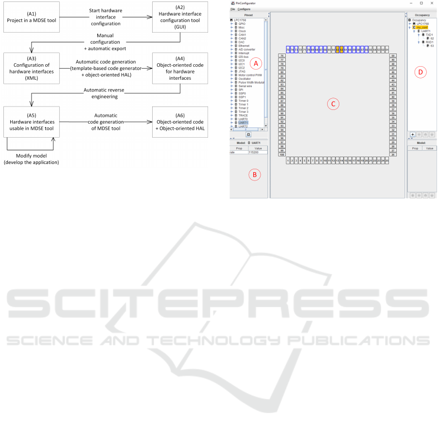
Figure 1: Overview of the development workflow used in
this paper.
2 OVERVIEW OF THE
APPROACH
This section presents an overview of the development
workflow used for the approach presented in this pa-
per. The workflow is shown in Figure 1. Only one
direction of the workflow is shown, with one phase
smoothly transitioning into the next. In practice, iter-
ations and returning to a prior phase for modifications
is often necessary. In order to improve the legibility
of the figure, this is not shown in Figure 1.
At the beginning of the workflow, a project within
an MDSE tool exists, i.e., a set of UML diagrams
that describe the structure and behavior of the appli-
cation (cf. (A1) in Figure 1). The diagrams may al-
ready describe the whole application minus the hard-
ware interactions. Alternatively, the diagrams may
be empty at this point in time and modified later in
step (A5) of the workflow shown in Figure 1. From
this MDSE tool, a separate GUI tool may be started
(cf. (A2) in Figure 1). This tool enables develop-
ers to specify the hardware interfaces their applica-
tion uses, as well as configure the initialization for
these hardware elements. The tool is described in de-
tail in Section 3. Once the developer has finished his
configuration,it may be exported automatically as an
XML file (cf. (A3) in Figure 1). The XML file serves
as the input to a code generation engine, that gener-
ates source code for the exported configurations of the
hardware interfaces (cf. (A4) in Figure 1). The gen-
erated source code utilizes an object-oriented HAL,
which is introduced in Section 4 of this paper. The
employed HAL interfaces may subsequently be im-
ported into the MDSE tool via automatic reverse engi-
neering. This way, the HAL interfaces, and therefore
Figure 2: Screenshot of the GUI tool developed in this paper
for the purpose of configuring the hardware initialization of
microcontrollers.
hardware interactions, are accessible to developers
within the MDSE tool in an object-oriented fashion
(cf. (A5) in Figure 1). As the hardware is now acces-
sible within the model, a developer may now develop
the whole application within the model in an object-
oriented manner. With our approach, the developer
is no longer required to include manual references to
low-level hardware interactions at the register-level.
Once this process is finished, the MDSE tool is capa-
ble of generating the source code for this application
automatically. For compilation, the implementation
of the HAL interfaces for the actual microcontroller
used in the project has to be linked with the generated
source code (cf. (A6) in Figure 1).
3 PinConfig TOOL
This section describes a novel GUI tool designed
to configure the hardware interfaces of a microcon-
troller. It is used in steps (A2) and (A3) of the work-
flow described in Section 1. The tool is referred to as
PinConfig tool for the remainder of this paper. Sec-
tion 3.1 presents the actual GUI of the tool, while Sec-
tion 3.2 describes how the characteristics of micro-
controllers are stored internally. Section 3.3 presents
the XML format used to store the configurations for a
specific microcontroller in a specific project.
Seamless Integration of Hardware Interfaces in UML-based MDSE Tools
235

3.1 Graphical User Interface
Figure 2 shows the GUI of the PinConfig tool.
Panel A contains a list view, where the current mi-
crocontroller that is configured is displayed on top
(LPC1768 (NXP, 2021a) in Figure 2). In the remain-
der of the list view, the different hardware interfaces
of the microcontroller are displayed. In Figure 2, the
UART1 interface of the LPC1768 is selected. Panel
B shows additional configuration values for the inter-
face currently selected in panel A. In Figure 2, this is
the baudrate of the UART selected in panel A.
Panel C shows the board layout of the microcon-
troller and enables users to select the pins to use for
the hardware interface highlighted in panel A. The
pins that may be chosen are highlighted with a blue
border, while the pins that have actually been cho-
sen are marked yellow. In Figure 2, the pins 62 and
63 are configured as a transmitting and receiving pin
for UART1 respectively. Figure 2 shows a Quad Flat
Package (QFP) structure of the pins of the microcon-
troller, i.e., the pins are located at the sides of the mi-
crocontroller. The tool also supports the Ball Grid Ar-
ray (BGA) structure, where the pins are located under
the bottom of the chip.
Panel D shows the currently configured hard-
ware interfaces of the microcontroller. In Figure 2,
UART1 is configured to use the pin 62 for transmis-
sion (TXD1) and pin 63 for reception (RXD1). The
purpose, for which a pin is used, e.g., marking pin 62
as TXD1, may be selected in a separate submenu.
3.2 Representing Microcontrollers
The GUI presented in Section 3.1 contains a variety
of information about the microcontroller that is con-
figured, e.g., the board structure, the available hard-
ware interfaces and the roles these interfaces may per-
form. This section describes a novel XML file that is
used to describe the structure of the microcontroller
internally. Listing 1 shows the general structure of
the XML file.
At the start of the XML file (lines 1-6) in Listing 1,
the basic information about the microcontroller, e.g.,
its name, the number of its pins and the board lay-
out (e.g., LQFP or BGA) is stated. The information
about the hardware interfaces is divided among the
following tags, <interfaces>, <roles> and <pins>.
The <interfaces> tag represents an actual interface,
e.g., a UART, while the <pin> tag represents the
pins that are available on the microcontroller. The
<role> tag serves as a foreign key between these el-
ements, thereby enabling the PinConfig tool to high-
light which pins are available for a specific interface
1 < m i c r o c o n t r o l l e r i d =” l pc 1 7 6 8”>
2 <i n f o>
3 <name>LPC1768</name>
4 <p i n co u n t >100</ p in c o u n t>
5 <pack a ge>LQFP</p a ckage>
6 </ i n f o>
7 <i n t e r f a c e s >
8 <!−−c f . L i s t i n g 2−−>
9 </ i n t e r f a c e s >
10 <r o l e s >
11 <!−−c f . L i s t i n g 3−−>
12 </ r o l e s >
13 <p i ns>
14 <!−−c f . L i s t i n g 4−−>
15 </ p in s>
16 </ m i c r o c o n t r o l l e r >
Listing 1: General XML structure for representing a micro-
controller.
1 < i n t e r f a c e i d =” u a r t 0”>
2 <p r o p s>
3 <p r o p name=” r a t e ”>115200</ prop>
4 <!−− . . . −−>
5 </ p r o p s>
6 <name>UART0</name>
7 <r o l e s >
8 <r o l e i d =” tx d 0”></ r o l e >
9 <!−−...−−>
10 </ r o l e s >
11 </ i n t e r f a c e >
Listing 2: The structure of the <interface> XML element.
on a given microcontroller.
Listing 2 shows the <interface> tag. Besides
the name of the hardware interface it belongs to (cf.
UART0 in line 6 in Listing 2), the tag also contains the
properties of this hardware interface. For example, in
line 3 of Listing 2 the property rate is defined, indicat-
ing that the interface UART0 contains a property that
represents the baudrate of the UART. The following
value (115200) represents a default value that may be
changed in the GUI described in Section 3.1. Lines 7-
10 of Listing 2 indicate the possible roles the UART
may perform.
While roles are referenced via their id in the in-
terface elements, they are defined in their own XML
elements. This is shown in Listing 3. Besides intro-
ducing the id that is also referenced by the interface
elements (cf. line 1 in Listing 3), the roles may con-
tain a set of properties (cf. line 2-5 in Listing 3), a
note that contains the information from the data sheet
of the microcontroller (cf. line 6 in Listing 3) and a
symbol for this role that is shown in the GUI of the
tool (cf. line 7 in Listing 3).
Listing 4 shows the pin element, which gives each
pin a name (cf. line 3 in Listing 4) and a position on
the board, which may be obtained from the data sheet
ICSOFT 2021 - 16th International Conference on Software Technologies
236
1 < r o l e i d =” tx d 0”>
2 <p r o p s>
3 <p r o p name=” t y p e”>O</ p rop>
4 <!−−...−−>
5 </ p r o p s>
6 <n o t e>T r a n s m i t t e r f o r UART0. < / n o t e>
7 <symbol>TXD0</symbol>
8 </ r o l e >
Listing 3: The structure of the <role> XML element.
of the microcontroller (cf. lines 4-7 of Listing 4). Fur-
thermore, each pin may reference a set of roles, e.g.,
txd0 in line 9 of Listing 4.
1 <pi n i d =”98”>
2 <p r o p s> </props>
3 <name>98</name>
4 <p o s i t i o n >
5 <x>0</x>
6 <y>23</y>
7 </ p o s i t i o n >
8 <r o l e s >
9 <r o l e i d =” tx d 0 ”/>
10 <!−−...−−>
11 </ r o l e s >
12 </ p i n>
Listing 4: The structure of the <pin> XML element.
3.3 Representing Hardware
Configurations
The GUI described in Section 3.1 is capable of cre-
ating an XML file in which the current configura-
tions regarding the pins and properties are exported.
The structure of the XML file is shown in List-
ing 5. The XML tags used in Listing 5 are similar
to those introduced in Section 3.2. However, where
the tags in Section 3.2 describe the possible configu-
rations for a microcontroller, the tags in Listing 5 re-
fer to a specific configuration for a specific project in
which the microcontroller is used. Therefore, some
tags have the prefix configured prepended. The tag
<configured interface> describes the specific config-
uration for an interface (a UART in line 3-19 of List-
ing 5). The tag <configured role> describes the con-
figuration of a specific role that the interface is config-
ured for (in contrast to a possible role, which the inter-
face may be configured for, as in the <role> tag intro-
duced in Section 3.2). This includes the pin on which
the role is actually performed (<configured pin>),
e.g., pin 98 in line 15 of Listing 5). The <prop> tag is
still employed to provide further configurations, e.g,
the baudrate for the configured UART (cf. line 6 in
Listing 5).
1 <o ccup a ncy>
2 <c o n f i g u r e d i n t e r f a c e s >
3 <c o n f i g u r e d i n t e r f a c e >
4 <name>UART0</name>
5 <p r o p s>
6 <p r o p name=” r a t e ”>115200</ prop>
7 </ p r o p s>
8 <c o n f i g u r e d r o l e s >
9 <c o n f i g u r e d r o l e >
10 <p r o p s>
11 <p r o p name=” t y p e”>o</prop>
12 </ p r o p s>
13 <symbol>TXD0</symbol>
14 <c o n f i g u r e d p i n >
15 <id >98</id>
16 </ c o n f i g u r e d p i n >
17 </ c o n f i g u r e d r o l e >
18 </ c o n f i g u r e d r o l e s >
19 </ c o n f i g u r e d i n t e r f a c e >
20 <!−−...−−>
21 </ c o n f i g u r e d i n t e r f a c e s >
22 </ o c cupa n cy>
Listing 5: XML structure of the export format describing
the hardware configurations selected by the developer.
4 GENERATION OF
INITIALIZATION CODE FOR
HARDWARE INTERFACES
The goal of this paper is a seamless integration of
hardware accesses in UML-based MDSE environ-
ments. For this, the hardware has to be represented
in an object-oriented fashion (cf. Section 4.2), while
low-level code statements should be generated auto-
matically wherever possible (cf. Section 4.3 and 4.4).
For this purpose, this paper refers to a specific project
structure and certain key files, which are introduced
in Section 4.1. The aspects described in this section
belong to the steps (A4) and (A5) of the development
workflow presented in Section 2.
4.1 Project Structure
The generation process described in Section 4 makes
use of several file types. This section presents an
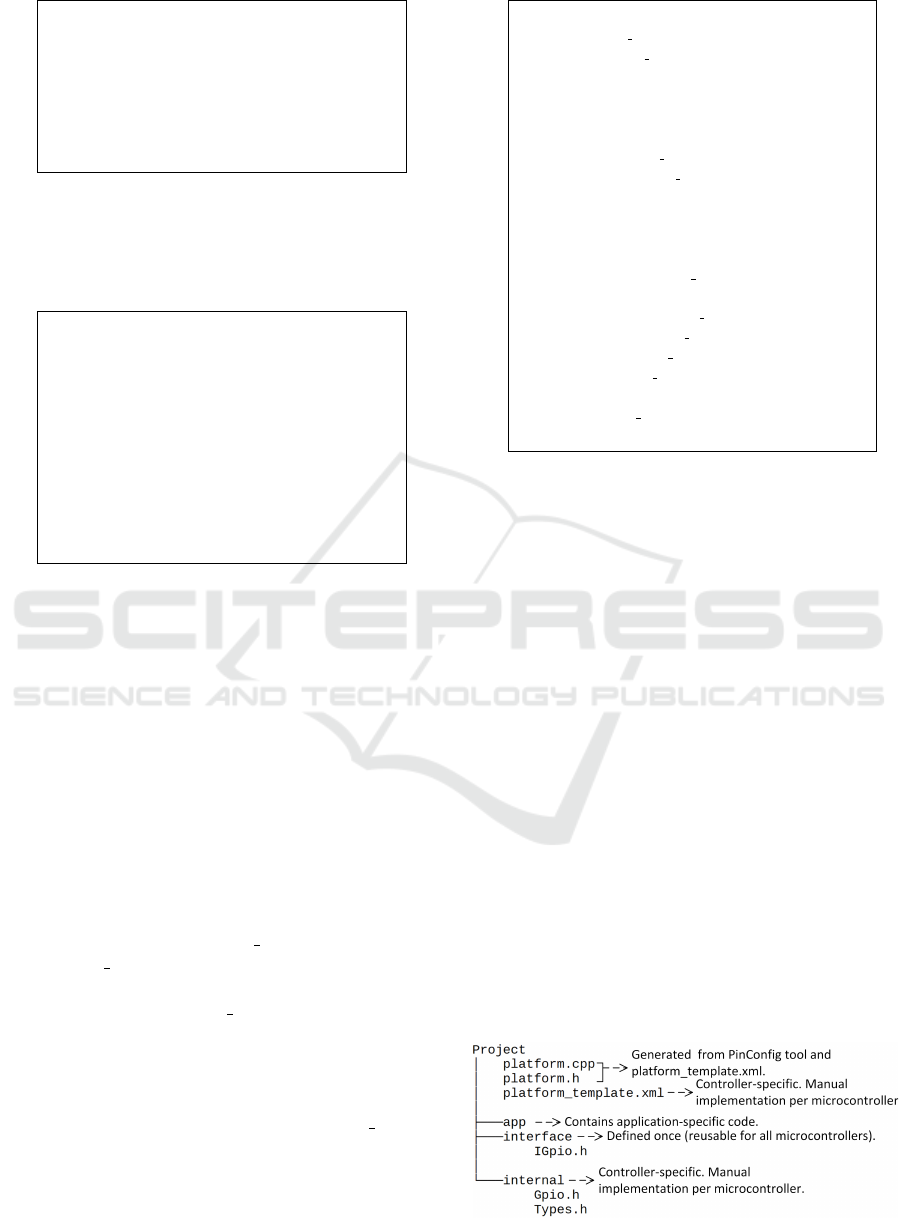
Figure 3: Overview of the different files used in Section 4.
Seamless Integration of Hardware Interfaces in UML-based MDSE Tools
237
overview of these files (cf. Figure 3). The appli-
cation itself is developed in the directory app. For
this, an object-oriented HAL may be used to access
the hardware. The interfaces of this HAL are stored
in the directory interface. These interfaces only have
to be defined once and may be reused for all micro-
controllers that have been considered during the cre-
ation of the HAL. The implementation of these inter-
faces depends on the specific microcontroller used in
the project and may be found in the directory inter-
nal. This implementation has to be created manually
once per microcontroller. It is reusable for all projects
that utilize the same microcontroller. The initializa-
tion code for the hardware interfaces is contained in
platform.h and platform.cpp (cf. Listing 8 and 9 intro-
duced in Section 4.3). These two files are generated
automatically from the file platform template.xml (cf.
Listing 10 introduced in Section 4.4). The structure of
platform template.xml is similar for every microcon-
troller, but requires controller-specific additions that
specify the exact commands available for the hard-
ware initialization of the specific controller.
In case an existing application should be ported
to another microcontroller, only two manual steps are
necessary. The content of the directory internal has to
be changed to the implementation for the new micro-
controller. Furthermore, platform template.xml has to
be replaced by the version specific to the new micro-
controller. In case the original microcontroller used to
develop the application and the new microcontroller
to which the application is ported provide similar ca-
pabilities, the application itself (inside the app direc-
tory) does not require any changes for the porting pro-
cess.
4.2 Object-oriented HAL
The PinConfig tool described in Section 3 may be
used to configure and automatically generate the ini-
tialization code for hardware interfaces (cf. Sec-
tion 4.4 for the automatic generation). Without this,
developers would have to deal with low-level code
constructs in MDSE tools. However, besides the ini-
tialization code for the hardware interfaces, develop-
ers also have to interact with low-level code in or-
der to access the hardware interfaces at runtime, e.g.,
to query the state of a GPIO. This section presents
an object-oriented HAL that may be integrated with
MDSE tools (cf. Section 5), thereby eliminating this
type of low-level code interactions at runtime as well.
As a complete HAL that encompasses virtually ev-
ery available hardware interface is a task associated
with a tremendous amount of work and resources, we
choose to limit ourselves to some of the most com-
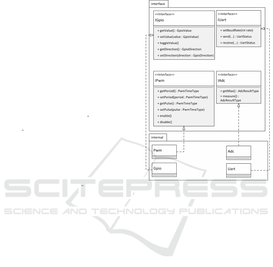
Figure 4: UML 2.5 class diagram of the structure of the
HAL. Three dots (...) are used as method parameters for
method signatures that are too long for the Figure. The Fig-
ure omits some template parameters (cf. Listing 7 and its
description).
mon hardware interfaces in this paper, namely GPIO,
ADC, UART and Pulse Width Modulation (PWM).
Other hardware interfaces may be integrated into the
HAL following the same principles.
In order to create the HAL, we studied mi-
crocontrollers from different manufacturers concern-
ing the previously mentioned hardware interfaces.
We studied microcontrollers from the manufactur-
ers Microchip (Microchip, 2021), Infineon (Infineon,
2021c), NXP (NXP, 2021a), ST Microelectronics (ST
Microelectronics, 2021b) and Espressif (Espressif,
2021). While the usage possibilities of the hardware
interfaces for the studied microcontrollers at runtime
is relatively consistent (e.g., a UART may send or re-
ceive data), the configuration of these hardware inter-
faces often differs more strongly between the differ-
ent microcontrollers. Therefore, the HAL presented
in this paper only abstracts the runtime usage of the
aforementioned hardware interfaces. Characteristics
that are related to the initial configuration and usually
remain constant during the execution of the applica-
tion, still require some controller-specific code. This
code is integrated via an automatic code generation
ICSOFT 2021 - 16th International Conference on Software Technologies
238
process and is explained in Section 4.4.
Figure 4 shows a UML class diagram of the hard-
ware interfaces and the abstraction of their function-
ality that is used during runtime. For legibility pur-
poses, the number of methods per hardware interface
in Figure 4 is reduced to the most common functions
for each hardware interface. The idea of Figure 4
is that developers implement their application with
the respective interfaces from the interface pack-
age, thereby gaining independence from a specific
hardware platform. The implementations of these in-
terfaces exist in the package internal. These im-
plementations differ for different hardware platforms.
Therefore, in case an application written with the
interface package should be ported to another plat-
form, the internal package has to be replaced by an-
other package that implements the HAL functionality
for the new hardware platform. While Figure 4 shows
four hardware interfaces that have been realized in
the HAL presented in this paper (GPIO, ADC, PWM,
UART), the remainder of Section 4 only refers to the
GPIO interface for legibility purposes. Moreover, the
examples refer to the Infineon Aurix TC297 (Infineon,
2021a) microcontroller. The presented concepts may
be applied analogously to the other hardware inter-
faces shown in Figure 4.
Figure 4 shows data types specific to each hard-
ware interface, e.g., GpioValue and GpioDirection
for the interface IGpio. In this example, GpioValue
indicates the current digital value of the GPIO, while
GpioDirection indicates whether the specific GPIO
is configured as an input or output. Often, microcon-
trollers provide their own type definitions for these
values. The HAL shown in Figure 4 abstracts these
type definitions for the respective microcontrollers,
in order to provide a consistent API for develop-
ers regardless of the specific hardware platform on
which the application should be executed. For this,
a mapping between the abstracted data types and the
data types specific to microcontrollers is required. In
the context of this paper, this is achieved by the file
Types.h, which contains such mappings. Listing 6
shows an excerpt of this file for the GPIO interface.
In line 5 of Listing 6, the abstract type GpioValue
is defined as the specific type IfxPort State in case
the HAL is executed on an Aurix TC297 microcon-
troller. Line 6 and 7 of Listing 6 show another im-
portant concept contained in Types.h, i.e., the ab-
straction of constants. Constant values, e.g., for set-
ting a GPIO to a high (GpioHigh in Listing 6) or low
(GpioLow in Listing 6) voltage, may be used by de-
velopers to configure a GPIO in a designated way.
Similar to the abstraction of types, as explained for
GpioValue above, constants may be abstracted by the
1 # i f n d e f HOLMES TYPES H
2 # d e f i n e HOLMES TYPES H
3 name s pace h o lmes {
4 / / Gpio
5 t y p e d e f I f x P o r t S t a t e Gpio V alue ;
6 s t a t i c c o n s t Gp ioVa l ue GpioLow =
I f x P o r t S t a t e l o w ;
7 s t a t i c c o n s t Gp ioVa l ue G pioHigh =
I f x P o r t S t a t e h i g h ;
8 / / [ . . . ]
9 }
10 # e n d i f / / # i f n d e f HOLMES TYPES H
Listing 6: Excerpt of the type definitions used in the HAL
(Types.h).
HAL to increase the independence of the application
code from a specific hardware platform.
Listing 7 shows an excerpt of an example imple-
mentation of the GPIO interface realization. It uses
the types defined in Types.h. Moreover, template pa-
rameters are used to specify compile time constants
that refer to hardware aspects used by the hardware
interface. In Listing 7, this is the pin and the port
which the GPIO should use (line 4). In Figure 4,
these template parameters have been omitted to im-
prove legibility. Besides the template parameters that
specify hardware aspects, the methods provided by
the IGpio interface have to be overridden in the in-
terface realization. Listing 7 shows this exemplary in
lines 12-14 for the method setValue().
1 # i f n d e f HOLMES INTERNAL GPIO H
2 # d e f i n e HOLMES INTERNAL GPIO H
3 name s pace h o lmes {
4 t e m p l a t e <u i n t 8 t p o r t , u i n t 8 t p i n>
5 c l a s s Gpio : p u b l i c h olme s : : I G p i o {
6 p r i v a t e :
7 v o l a t i l e I f x P
*
p o r t ;
8 p u b l i c :
9 Gpio ( ) {
10 p o r t = ( I f x P
*
) (0 xF003A000u + 0
x100u
*
p o r t ) ;
11 }
12 v o i d s e t V a l u e ( Gpi o Valu e v a l u e ) {
13 I f x P o r t s e t P i n S t a t e ( p o r t , p i n ,
v a l u e ) ;
14 }
15 / / [ . . . ]
16 }
17 }
18 # e n d i f / / # i f n d e f HOLMES INTERNAL GPIO H
Listing 7: Excerpt of the implementation of the GPIO HAL
interface for the Aurix TC297 microcontroller.
4.3 Hardware Initialization
Section 4.2 introduced an object-oriented HAL that
requires hardware-specific values for the usage of an
Seamless Integration of Hardware Interfaces in UML-based MDSE Tools
239

object of the HAL. For example, the port and pin of
the respective GPIO have to be passed as template pa-
rameters in Listing 7. This type of information is al-
ready configured in the PinConfig tool described in
Section 3 and may therefore be generated automat-
ically from the corresponding export format of the
tool (cf. Section 3.3). Then, a set of type definitions
may be used to enable developers to access a respec-
tive GPIO via an identifier configured in the PinCon-
fig tool, thereby precluding that a developer has to
know the port and pin on which the GPIO operates.
These type definitions are stored in a file called plat-
form.h, which may be automatically generated (cf.
Section 4.4 for the generation process). An excerpt
of platform.h is shown in Listing 8. The $ signs in
Listing 8 indicate a placeholder variable that should
be replaced with an actual value, i.e., the actual port
on which the GPIO should operate.
1 # i f n d e f HOLMES PLATFORM H
2 # d e f i n e HOLMES PLATFORM H
3 name s pace h o lmes {
4 $ { g p i o h a l }
5 / / [ . . . ] more t y p e d e f i n i t i o n s
6 voi d i n i t ( ) ;
7 }
8 # e n d i f / / # i f n d e f HOLMES PLATFORM H
Listing 8: Excerpt of the type definitions that allow develop-
ers to refer to hardware interfaces with custom names (plat-
form.h). The $ symbol indicates a placeholder variable.
In line 4 of Listing 8 a placeholder, ${gpio hal},
is used to represent type definitions which provide
an alias for a GPIO on a specific port and pin.
The number of type definitions equals the number
of GPIO interfaces that have been configured in
the PinConfig tool presented in Section 3. These
placeholders may themselves contain more place-
holders, e.g., for specifying the specific port and pin
of the GPIO. Thus, ${gpio hal} consists of a num-
ber of statements of the following form: typedef
internal::Gpio<$port, $pin> $name;. The
values of the placeholders may be extracted automat-
ically from the output format of the PinConfig tool
described in Section 3.3. Thus, developers may spec-
ify a name for a specific GPIO they wish to use in the
PinConfig tool, which may subsequently be used by
the developers to instantiate an instance of the specific
GPIO within their program. Besides the type defi-
nitions, platform.h declares the init() method (cf.
line 6 in Listing 8), which configures the hardware in-
terfaces according to the output format of PinConfig
tool presented in Section 3.3. The definition of this
method may be found in the file platform.cpp, which
may also be automatically generated (cf. Section 4.4).
The structure of platform.cpp is shown in Listing 9.
1 ${ g p i o p r e }
2 s t a t i c v o id i n i t G p i o ( ) {
3 $ { g p i o h e a d e r }
4 $ { gp i o b o dy }
5 $ { g p i o f o o t e r }
6 }
7 / / [ . . . ] T e m pl a t es o t h e r h a r d w ar e i n t e r f a c e s
8 v o i d ho lmes : : i n i t ( ) {
9 i n i t G p i o ( ) ;
10 / / [ . . . ] I n i t i a l i z e o t h e r i n t e r f a c e s
11 }
Listing 9: Structure of the hardware initialization (plat-
form.cpp). The $ symbol indicates a placeholder variable.
In line 8-11 of Listing 9, the aforementioned init()
method is defined. In essence, this simply defers the
initialization process to the initialization methods for
each specific hardware interface. In Listing 9, such
a specific initialization method is shown in lines 2-
6. The placeholder ${gpio header} is replaced by
code that should only be executed once before the ini-
tialization of every GPIO. Conversely, ${gpio footer}
is replaced by code that should only be executed
once after the initialization of every GPIO. The
${gpio body} placeholder is replaced by the specific
configurations for each individual GPIO. An exam-
ple for this is the line IfxPort setPinMode((Ifx P
*)&MODULE P${port}, ${pin}, ${mode}) for the
Aurix TC297 microcontroller, which sets the port
and pin of the GPIO, as well as whether it is ini-
tially configured as an input or an output. The place-
holders of this line may once again be automatically
extracted from the output format of the PinConfig
tool presented in Section 3.3. Besides the aforemen-
tioned placeholders, line 1 of Listing 9 shows the
${gpio pre} placeholder, which may provide addi-
tional initializations that may be accessed from within
initGPIO().
4.4 Code Generation for Hardware
Initialization
Section 4.3 introduced the files platform.h and plat-
form.cpp, which contain the initialization code for the
hardware interfaces as configured with the PinConfig
tool presented in Section 3.1. This section shows how
those files are generated automatically. Listing 10
shows the structure of platform template.xml.
At the start of Listing 10 the template structure
of the files platform.h and platform.cpp is stored (cf.
the previously introduced Listing 8 and 9 for the re-
spective structures). The remainder of Listing 10 (cf.
line 10-25) contains information about the controller-
specific commands to initialize a hardware interface.
ICSOFT 2021 - 16th International Conference on Software Technologies
240

1 <c o d e g e n e r a t o r >
2 <h e a d e r f i l e >
3 <!−− Tem p l a t e h o l m e s p l a t f o r m . h
4 ( c f . L i s t i n g 8 )−−>
5 </ h e a d e r f i l e >
6 <s o u r c e f i l e >
7 <!−− Tem p l a t e h o l m e s p l a t f o r m . cpp
8 ( c f . L i s t i n g 9 )−−>
9 </ s o u r c e f i l e >
10 <i n t e r f a c e s >
11 <gpio>
12 <g p i o h a l >
13 t y p e d e f i n t e r n a l : : Gpio& l t ; $ { p o r t } ,
14 $ { p i n }&g t ; ${name } ;
15 </ g p i o h a l >
16 <g p i o p r e ></g p i o p r e >
17 <g p i o h e a d e r ></g p i o h e a d e r >
18 <g p i o b ody>
19 I f x P o r t s e t P i n M o d e ( ( I f x P
*
)& ;
MODULE P${ p o r t } , $ { pi n } , $ {
mode }) ;
20 </ g p io body>
21 <g p i o f o o t e r ></ g p i o f o o t e r >
22 </ g pio>
23 <!−− . . . −−>
24 </ i n t e r f a c e s >
25 </ c o d e g e n e r a t o r >
Listing 10: XML file used as a template to generate
the hardware initialization (platform template.xml). The $
symbol indicates a placeholder variable. Note that some
special characters have to be used because of the XML
syntax, e.g., < to represent the symbol <.
For example, in Listing 9 (platform.cpp), the template
variable gpio body is used to specify the initialization
process for each GPIO. In lines 18-20 of Listing 10,
the controller-specific commands for this initializa-
tion process are stored. Similarly, lines 12-15 define
the type definition required for the gpio hal template
variable that is used in Listing 8 (platform.h).
Generating the initialization files platform.h and
platform.cpp automatically may be achieved by it-
erating through every hardware interface configured
in the output format of the PinConfig tool (cf. Sec-
tion 3.3). For each hardware interface of the same
type X, e.g., GPIO, and for each sub-tag in the
<gpio> tag of Listing 10 (cf. lines 12-21, e.g.,
<gpio hal>), a string builder X
i
is created. For
example, a separate string builder X
i
is created
for the <gpio hal>, <gpio pre>, <gpio header>,
<gpio body> and <gpio footer> tags. The string
builders X
i
are appended with the content from the re-
spective sub-tags of Listing 10. During this append-
ing, the remaining placeholder values in Listing 10,
e.g., ${pin}, are filled with the configured values from
the output format of the GUI tool. Thus, once every
hardware interface that is configured in the output for-
mat of the PinConfig tool has been iterated through,
the string builders X
i
contain the initialization infor-
mation of every configured hardware interface. For
example, the string builder for ${gpio hal} contains
the type definitions for all configured GPIO interfaces
in the output format. The string builders X
i
may then
subsequently be used to replace the other placehold-
ers for platform.h and platform.cpp, which are stored
in lines 2-9 of Listing 10. Thus, the templates for
platform.h and platform.cpp no longer contain any
placeholders and the actual files platform.h and plat-
form.cpp may be generated by copy-pasting the con-
tent from the templates in a newly created file.
5 INTEGRATION WITH MDSE
TOOLS
The results from Section 4 allow developers to inter-
act with hardware in an object-oriented abstract man-
ner, as well as the automatic code generation of the
initialization code for hardware interfaces. However,
these elements are not yet integrated in an MDSE de-
velopment process, as the results from Section 4 only
exist as code. This section describes how this gener-
ated code, as well as the PinConfig tool described in
Section 3.1, may be integrated with MDSE tools.
Before the actual integration process is described,
we remark upon the heterogeneity of current MDSE
tools. As these tools are developed by different
providers, their customization options for developers
differ. Thus, integration of our approach with these
tools may differ slightly for each tool. However, the
principle is similar for each tool. In the following, the
provided examples are based on the MDSE tool IBM
Rational Rhapsody (Rhapsody, 2020).
1) Starting the Hardware Configuration Tool from
the GUI of the MDSE Tool. While the GUI tool
presented in Section 3 may be started as a standalone
application, it may also be started from an MDSE
tool. Furthermore, such an integration in the MDSE
tool allows for an integration of the subsequent code
generation process (cf. Section 4.4) in the MDSE
tool as well. In IBM Rational Rhapsody, this may
be achieved by the use of so called helper files that
may add entries to Rhapsody’s menus and execute ar-
bitrary Java code once such an entry is clicked.
2) Integrating the HAL Into the MDSE Tool Via
Reverse Engineering. The HAL described in Sec-
tion 4 exists as source code. In order to use this code
in MDSE tools and enable an object-oriented access
Seamless Integration of Hardware Interfaces in UML-based MDSE Tools
241
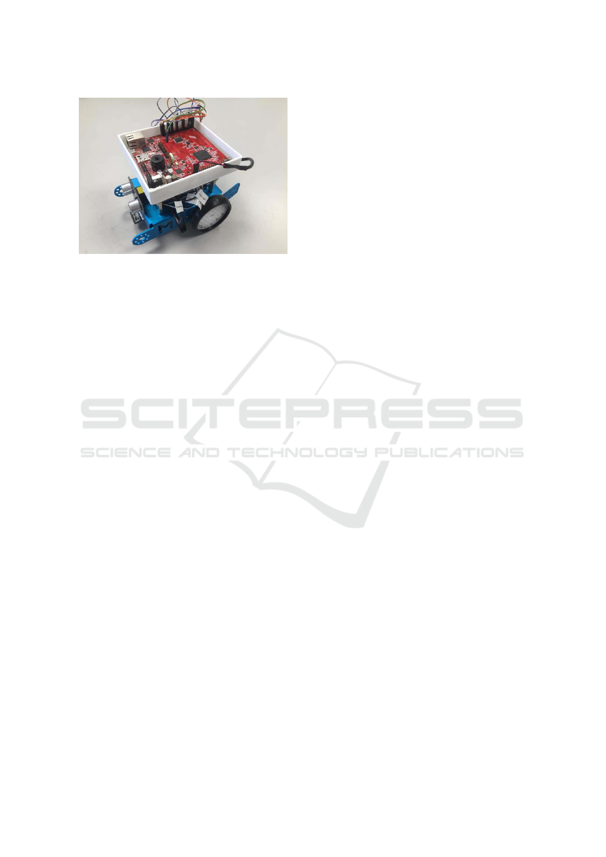
Figure 5: Picture of the modified mBot platform as used in
this paper. The microcontroller on top of the mBot is an
Aurix TC297.
of hardware interactions, corresponding classes either
have to be created manually by the developer in the
MDSE tool or created automatically via the reverse
engineering functionality of the MDSE tool. In IBM
Rational Rhapsody, the reverse engineering process
may be executed automatically via a dedicated Java
API. Thus, in our prototype implementation, this pro-
cess is automatically performed after configuration
of the hardware interfaces via the PinConfig tool has
ended.
3) Include HAL and Platform Files During Com-
pilation. Once the code for the application has been
created from the model with the MDSE tool’s code
generation, the HAL and the automatically generated
platform.h and platform.cpp files have to be linked
during compilation.
6 USE CASE
We evaluated our approach for a small embedded ap-
plication example, i.e., a toy car that is capable of au-
tonomous driving. For this, we modify the Makeblock
mBot platform (Makeblock, 2021) with a custom con-
verter board. This converter board enables the use of
3.3V and 5V microcontrollers with the mBot, as well
as the use of the GPIO, UART, ADC und PWM hard-
ware interfaces. The GPIOs are used to control LEDs
and read digital values from sensors, i.e., an ultrasonic
sensor in this application. The ultrasonic sensor is
used to detect obstacles in front of the mBot. The
ADC is used to digitalize the luminosity levels mea-
sured by sensors below the mBot. This enables the
mBot to autonomously follow a set trajectory, pro-
vided the path of the trajectory contains a different
brightness level than the rest of the track. For exam-
ple, this may be achieved by printing a black line that
represents the path of the trajectory on white sheets
of paper. The PWM is used to control the motors of
the mBot, while the UART enables interaction with a
bluetooth chip. The bluetooth chip, in turn, is capable
of communicating with a smartphone application that
may be used to 1) control the mBot remotely, 2) start
its autonomous trajectory following driving mode and
3) enable the automatic obstacle avoidance enabled
through the ultrasonic sensors. Figure 5 shows an im-
age of the modified hardware platform with the Aurix
TC297 microcontroller connected.
For the purpose of this use case a software appli-
cation was created with an MDSE tool (IBM Ratio-
nal Rhapsody (Rhapsody, 2020)) that provides the ap-
plication logic for the functionality described above.
For hardware interactions, the HAL described in Sec-
tion 4 is used within the application model. In order
to show the effect of our approach on the portability
of applications, we selected five microcontrollers for
which the application should control the mBot. These
are a LPC1768 (NXP, 2021a), XMC4500 (Infineon,
2021c), STM32F4 (ST Microelectronics, 2021b) and
an Aurix TC279 (Infineon, 2021a). With the HAL
implementations for these microcontrollers, as de-
scribed in Section 4, the only step required for run-
ning the application on these different microcon-
trollers is the configuration of the hardware via the
PinConfig tool described in Section 3. By employ-
ing the code generation described in Section 4.4, the
remaining controller-specific code is generated auto-
matically. Thus, porting the application comes down
to specifying the hardware initialization for the new
microcontroller in the PinConfig tool.
7 RELATED WORK
This section describes related work to the approach
presented in this paper. This encompasses approaches
that describe a HAL, as well as approaches that gener-
ate some form of initialization code for the hardware
of microcontrollers.
Industrial tools that are capable of generating ini-
tialization code for the hardware of microcontrollers
include, e.g., (Infineon, 2021b; ST Microelectronics,
2021a; NXP, 2021b) . Most often, these tool are pro-
prietary and are developed by a specific manufacturer
of microcontrollers. In consequence, the tools only
support the configuration of microcontrollers for a
specific family of microcontroller, i.e., those offered
by the specific manufacturer. For example, (ST Mi-
croelectronics, 2021a) is limited to the configuration
ICSOFT 2021 - 16th International Conference on Software Technologies
242

of microcontrollers from ST Microelectronics. Our
approach, in contrast, provides a generic description
format for microcontrollers and their hardware inter-
faces (cf. Section 3) and may thus include microcon-
trollers from different manufacturers (cf. Section 6).
Furthermore, these tools do not consider the integra-
tion of the generated source code into MDSE tools
at all. This is exacerbated by the fact that most of
these tools do not create object-oriented source code.
Non-object-oriented source code is hard to integrate
with UML-based MDSE tools, as UML is an object-
oriented modeling language and supports non-object-
oriented concepts only in a limited fashion. Our ap-
proach, in contrast, couples the hardware initializa-
tion to an object-oriented HAL (cf. Section 4) and
may therefore be easily integrated into MDSE tools
(cf. Section 5).
Besides these industrial approaches, there are sev-
eral academic approaches for generating the initial-
ization code for the hardware interfaces of microcon-
trollers. In (Yunfei Bai et al., 2007; Bhanu et al.,
2009), an XML-based description methodology for
microcontrollers is described. It is intended for the
code generation of initialization code. However, their
description assumes direct hardware access for each
microcontroller, whereas our approach assumes the
usage of a HAL. Furthermore, their approach does not
generate object-oriented code and thus is hard to inte-
grate in MDSE tools. Nevertheless, their description
format served as an inspiration for our XML-based
description formats described in Section 3.
An approach that is limited to the generation of
source code for the MPC5644A microcontroller has
been presented in (Geng et al., 2012). Our approach,
in contrast, is extensible by design and may gener-
ate code for any microcontroller once the required
XML-files (cf. Section 3 and 4) are created. Fur-
thermore, their approach generates code for Mat-
lab/Simulink (MathWorks, 2021), while our approach
focuses on integration with UML-based MDSE tools.
Another approach for platform-independent
source code generation has been described in (Kim
et al., 2013). The platform-dependent characteristics
of the target platform are described with an Archi-
tectural Analysis Description Language (AADL),
which is supplemented by a code snippet repository.
Our approach, in comparison, uses an XML-based
format to describe the target microcontrollers and
relies on a HAL for the implementation of hardware
accesses instead of a code snippet repository. Due
to the use of an object-oriented HAL and UML, our
approach enables developers to work with UML-
based MDSE tools to develop their application. The
approach presented in (Kim et al., 2013), in contrast,
does not describe an integration with UML-based
MDSE tools and instead relies on other modeling
languages, e.g., Stateflow (MathWorks, 2021) or
UPPAAL (Behrmann et al., 2004).
Section 4 introduces an approach for the
seamless integration of object-oriented HALs into
MDSE. There exist other, non object-oriented HALs,
e.g., (ARM Limited, 2021a; ARM Limited, 2021b).
Due to their non-object-oriented nature, they are
harder to integrate with MDSE tools. The num-
ber of object-oriented HALs is relatively small,
e.g., (modm., 2021). Currently, these approaches do
not describe how they may be seamlessly integrated
with MDSE tools.
8 CONCLUSION
MDSE tools are often based on UML and its high-
level object-oriented concepts. The interaction with
hardware, which usually occurs through low-level
program code at the register level, often requires a
change in abstraction levels for the developer. More-
over, due to the hardware interactions not being
object-oriented, MDSE tool support for such hard-
ware interactions is lacking. This paper proposes an
approach how object-oriented HALs may be seam-
lessly integrated into MDSE tools to enable develop-
ers to develop embedded systems in a holistic, object-
oriented fashion. For this, we introduce a GUI tool
to configure hardware interfaces and provide an auto-
matic code generation approach that uses XML-based
template files. The resulting code may be automat-
ically imported into MDSE tools. We evaluated our
approach by developing an application example for
microcontrollers from three different manufacturers
(NXP, Infineon and ST Microelectronics). Due to the
use of our HAL, the application code could be ported
to the other microcontrollers with a minimum of mod-
ifications.
Future work includes an automated generation of
the XML files describing the structure of microcon-
trollers for the GUI tool in which the hardware is con-
figured. Furthermore, we envision a SysML (Object
Management Group, 2019)-like frontend for the GUI
tool that enables developers to specify the hardware
configuration without leaving their MDSE tool.
ACKNOWLEDGEMENTS
This work was partially funded by the German Fed-
eral Ministry of Economics and Technology (Bun-
Seamless Integration of Hardware Interfaces in UML-based MDSE Tools
243

desministeriums fuer Wirtschaft und Technologie-
BMWi) within the project “Holistic model-driven de-
velopment for embedded systems in consideration of
diverse hardware architectures” (HolMES). The au-
thors would like to thank Adrian Richter for software
development assistance, as well as Johannes Trageser
and Lars Donner for helpful comments on the HAL
and its integration in MDSE tools.
REFERENCES
ARM Limited (2021a). Cortex Microcontroller Software
Interface Standard (CMSIS) https://developer.arm.
com/tools-and-software/embedded/cmsis (accessed
on 25th March 2021).
ARM Limited (2021b). Mbed OS.
https://os.mbed.com/mbed-os/ (accessed on 11th
March 2021).
Behrmann, G., David, A., and Larsen, K. G. (2004). A Tuto-
rial on Uppaal, pages 200–236. Springer Berlin Hei-
delberg, Berlin, Heidelberg.
Bhanu, G. P., Bai, Y., Tan, S. L., and Chng, E. S. (2009). A
Generic MCU Description Methodology with Depen-
dency Evaluation. In 2009 International Conference
on Signal Processing Systems, pages 565–569.
Brambilla, M., Cabot, J., and Wimmer, M. (2012). Model-
Driven Software Engineering in Practice. Morgan &
Claypool Publishers.
Bunse, C., Gross, H.-G., and Peper, C. (2007). Applying a
model-based approach for embedded system develop-
ment. pages 121–128.
Charette, R. N. (2009). This car runs on code. IEEE spec-
trum, 46(3):3.
Espressif (2021). ESP32. http://esp32.net/ (accessed on
18th March 2021).
Geng, P., Ouyang, M., Li, J., and Xu, L. (2012). Embedded
C Code Generation Platform for Electric Vehicle Con-
troller. Advanced Materials Research, 546-547:778–
783.
Huning, L., Iyenghar, P., and Pulvermueller, E. (2020).
A workflow for automatically generating application-
level safety mechanisms from UML stereotype model
representations. In Proceedings of the 15th Interna-
tional Conference on Evaluation of Novel Approaches
to Software Engineering - Volume 1: ENASE, pages
216–228. INSTICC, SciTePress.
Infineon (2021a). 32-bit AURIX™ Microcontroller
based on TriCore™. https://www.infineon.com/
cms/de/product/microcontroller/32-bit-tricore-
microcontroller/(accessed: 13th January 2021).
Infineon (2021b). Dave.
https://www.infineon.com/dgdl/infineon-
dave introduction-dt-v01 00-
en.pdf?fileid=5546d462636cc8fb01645f681d4713ed
(accessed on 11th March 2021).
Infineon (2021c). XMC4500. https://www.infineon.com/
cms/de/product/microcontroller/32-bit-industrial-
microcontroller-based-on-arm-cortex-m/32-bit-
xmc4000-industrial-microcontroller-arm-cortex-
m4/xmc4500/ (accessed on 19th March 2021).
Kashif, H., Mostafa, M., Shokry, H., and Hammad, S.
(2009). Model-based embedded software develop-
ment flow. In 2009 4th International Design and Test
Workshop (IDT), pages 1–4.
Kim, B., Phan, L. T. X., Sokolsky, O., and Lee, L. (2013).
Platform-dependent code generation for embedded
real-time software. In 2013 International Conference
on Compilers, Architecture and Synthesis for Embed-
ded Systems (CASES), pages 1–10.
Makeblock (2021). mBot.
https://www.makeblock.com/mbot (accessed on
9th March 2021).
MathWorks (2021). Matlab.
https://www.mathworks.com/products/matlab.html
(accessed on 18th March 2021).
Microchip (2021). ATMegaA328-PU. https://www.
microchip.com/wwwproducts/en/ATmega328P
(accessed on 19th March 2021).
modm. (2021). modm: a barebone embedded library gener-
ator. https://modm.io/ (accessed on 16th March 2021).
NXP (2021a). https://www.nxp.com/products/processors-
and-microcontrollers/arm-microcontrollers/general-
purpose-mcus/lpc1700-cortex-m3/512kb-flash-64kb-
sram-ethernet-usb-lqfp100-package:lpc1768fbd100
(accessed on 18th March 2021).
NXP (2021b). MCUXpresso.
https://www.nxp.com/design/software/development-
software/mcuxpresso-software-and-tools-
/mcuxpresso-integrated-development-environment-
ide:mcuxpresso-ide (accessed on 11th March 2021).
Object Management Group (2019). OMG Systems Mod-
eling Language Version 1.6. Technical report, Object
Management Group.
OMG UML (2017). OMG Unified Modeling Language
Version 2.5.1. Technical report, Object Management
Group.
Rhapsody (2020). IBM. Rational Rhapsody Developer.
https://www.ibm.com/us-en/marketplace/uml-tools
(accessed 20th August 2020).
Selic, B. (2008). Personal reflections on automation, pro-
gramming culture, and model-based software engi-
neering. Automated Software Engineering, 15(3-
4):379–391.
ST Microelectronics (2021a). STM32CubeMX.
https://www.st.com/en/development-
tools/stm32cubemx.html (accessed on 11th March
2021).
ST Microelectronics (2021b). STM32F4XX.
https://www.st.com/en/microcontrollers-
microprocessors/stm32f4-series.html (accessed
on 19th March 2021).
Trindade, R., Bulwahn, L., and Ainhauser, C. (2014).
Automatically generated safety mechanisms from
semi-formal software safety requirements. In Bon-
davalli, A. and Di Giandomenico, F., editors, Com-
puter Safety, Reliability, and Security, pages 278–293,
Cham. Springer International Publishing.
Yunfei Bai, Eng Siong Chng, and Gorthi Prashant Bhanu
(2007). An mcu description methodology for ini-
tialization code generation software. In 2007 Inter-
national Conference on Parallel and Distributed Sys-
tems, pages 1–7.
ICSOFT 2021 - 16th International Conference on Software Technologies
244
