
Using BPMN for ETL Conceptual Modelling: A Case Study
Bruno Oliveira
1a
, Óscar Oliveira
1b
and Orlando Belo
2c
1
CIICESI, School of Management and Technology, Porto Polytechnic, Rua do Curral, Felgueiras, Portugal
2
ALGORITMI R&D Centre, University of Minho, Braga, Portugal
Keywords: Data Warehousing, ETL, Conceptual Modelling, BPMN.
Abstract: One of the most important parts of a Data Warehousing System is the Extract-Transform-Load (ETL)
component. It is responsible for extracting, transforming, conciliating, and loading data for supporting
decision-making requirements. Usually, due to the complexity of managing heterogeneous data, this
component is responsible for consuming most of the resources required for implementing a Data Warehousing
System, representing a critical component that compromises the adequacy of the system. Despite their
importance, the ETL development method is essentially ad-hoc, which does not always follow or embodies
the best practices. With the emergence of Big Data and associated tools, script-based ETL became, even more,
a common approach. In the last years, BPMN – Business Process Model and Notation – have been proposed
and used to support ETL conceptual models. Still, as an expressive language, it provides different approaches
for representing the same requirements. In this paper, we explore the use of BPMN for ETL conceptual
modelling, analyzing existing approaches, and proposing a set of guidelines for using this notation in a more
consistent way.
1 INTRODUCTION
Data Warehousing System (DWS) implementations
face some challenges due to the ever-growing need
for data. These challenges are most visible in typical
Extract, Transform and Load (ETL) tasks, which are
usually implemented in one of the most critical
components of a DWS.
The implementation of any analytical system is
strongly influenced by the correspondent populating
system's quality and adequacy (Kabiri & Chiadmi,
2013). Analyzing data with poor quality can provide
wrong insights that can have disastrous results in
business activities. GUI-based tools are a common
approach for ETL development, providing visual
constructs for defining workflows and pallets of
predefined tasks that are typically used in ETL
processes. They provide a certain standardization
degree since most of the available tasks encapsulate
best practices associated with specific application
scenarios. With the rise of Big Data, several code-
a
https://orcid.org/0000-0001-9138-9143
b
https://orcid.org/0000-0003-3807-7292
c
https://orcid.org/0000-0003-2157-8891
1
https://www.bpmn.org/
based tools emerged for taking advantage of specific
models and architectures. Despite their potential for
data integration, these tools make these procedures
very specific, requiring specialized knowledge to deal
with their design, implementation, and maintenance.
In the last years, Business Process Modelling and
Notation
1
(BPMN) (Aagesen & Krogstie, 2015)), is
being used for modelling (or representing) ETL
processes at higher levels of abstraction, allowing for
the development team to focus on the most critical
workflow aspects. The choice of BPMN for ETL
modelling is mainly due to its simplicity in
representing and modelling business processes,
coupled with its expressiveness.
In this paper, we explore the use of BPMN for
ETL conceptual modelling, analyzing some of the
existing approaches, and proposing a set of guidelines
to use this notation in a more standardized way. In the
remaining sections, we present some work related to
ETL modelling (Section 2), describe the
fundamentals of BPMN, focusing on ETL
development (Section 3), and present and discuss
Oliveira, B., Oliveira, Ó. and Belo, O.
Using BPMN for ETL Conceptual Modelling: A Case Study.
DOI: 10.5220/0010575702670274
In Proceedings of the 10th International Conference on Data Science, Technology and Applications (DATA 2021), pages 267-274
ISBN: 978-989-758-521-0
Copyright
c
2021 by SCITEPRESS – Science and Technology Publications, Lda. All rights reserved
267
how BPMN can be applied in ETL application
scenarios (Section 4). Finally, in Section 5, we
present conclusions and future work directions.
2 RELATED WORK
Considering ETL processes as a critical component
for DW implementation, the definition of a detailed
model will be beneficial throughout the entire process
development, installation, and validation, providing
to its architects and engineers a handy guide. The
ETL development is still firmly based on physical
characteristics used to support its execution, meaning
that the processes are developed considering specific
tools and languages constrained or framed by
architectural characteristics. While most of these
tools are very powerful for ETL execution, they do
not provide the necessary resources for documenting
and representing integration processes at a higher and
common abstraction model. With these problems in
mind, several authors made recognized and relevant
efforts to provide a methodology for ETL conceptual
modelling.
In (Vassiliadis et al., 2002) a new set of elements
is proposed for expressing ETL natural features,
while in (Simitsis & Vassiliadis, 2003) a
methodology for representing attribute mapping
between data sources and the DW schemas is
proposed. Another approach was proposed in
(Trujillo & Luj, 2003) with the goal to extend the
Unified Model Language
2
(UML) for minimizing
notations and methodology learning curve's efforts
and costs. (Dupor & Jovanovi, 2014) proposed a
method and notation focused on a simple visual
overview to simplify processes representation, and
(Biswas et al., 2017) an approach for exploring
requirement and activity diagrams of the Systems
Modelling Language (SysML). The conceptual
representation in SysML can also be transformed into
XML Metadata Interchange (XMI) format, allowing
its programable interpretation. More recently, in
(Biswas et al., 2019), the authors extended their work,
presenting how the SysML model's validation can be
automated. More recently, (Raj et al., 2020) presented
a conceptual way for modelling data pipelines. This
work covered an extended scope considering the use
of ETL/ELT transformations, independently of the
DW environment, several applications, and different
data types (e.g., continuous or batch). Some of the
approaches presented focus on specific notations,
which can cause an extra effort to the ETL
2
http://www.uml.org/
development team to learn the specifics of notation
and posteriorly to communicate to non-technical
users.
The adaptation of existing ETL notations can
reduce some of the referred problems since some of
them are already widely used and commonly
supported by a large diversity of modelling tools. In
(Akkaoui et al., 2009), it is stated that the ETL
process can be considered as a particular type of
business process, which can facilitate communication
with more technical and non-technical staff. Since
BPMN is a widely used notation for business process
modelling and execution, it is not rare to see it used
for helping in other scenarios.
A Model-Driven Development based vendor-
independent BPMN metamodel and automatic code
generation for any vendor-specific platform was
proposed (El Akkaoui et al., 2011). One year later, the
same authors addressed in (El Akkaoui et al., 2012)
two architectural layers related to the specification of
ETL processes using BPMN, namely: process
orchestration, which can be accomplished by several
BPMN elements, like events and flow control
gateways, and data process operations, which are
related to some specific operations that allow for the
manipulation of data among several data sources
coordinated by control process elements. Meanwhile,
other approaches emerged, such as a Pattern-Oriented
Approach proposed by (Oliveira & Belo, 2015). In
this proposal, patterns represent some of the most
commonly used ETL procedures, such as change data
capture, Slowly-Changing Dimensions, or Data
Quality Enhancement, among others. These authors
used a Collaboration Diagram to represent
independent components' interaction (patterns),
providing a first approach to a multi-layer ETL
system using BPMN, showing in a simpler way how
ETL patterns can be used for supporting ETL
conceptual modelling with BPMN.
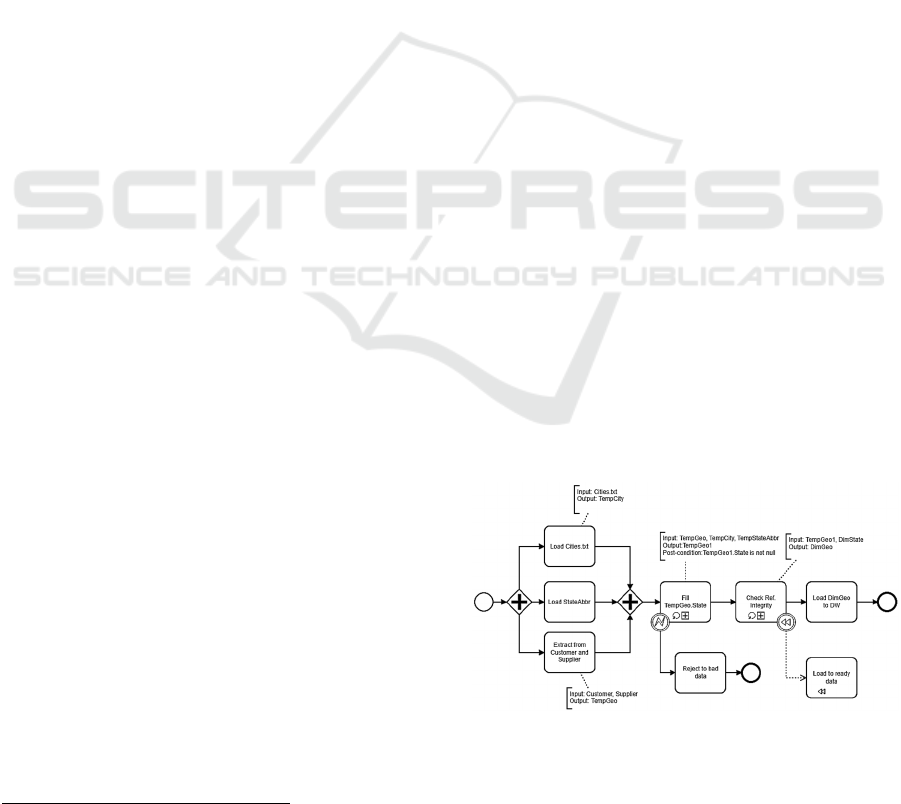
Figure 1: ETL process modelled using BPMN.
DATA 2021 - 10th International Conference on Data Science, Technology and Applications
268
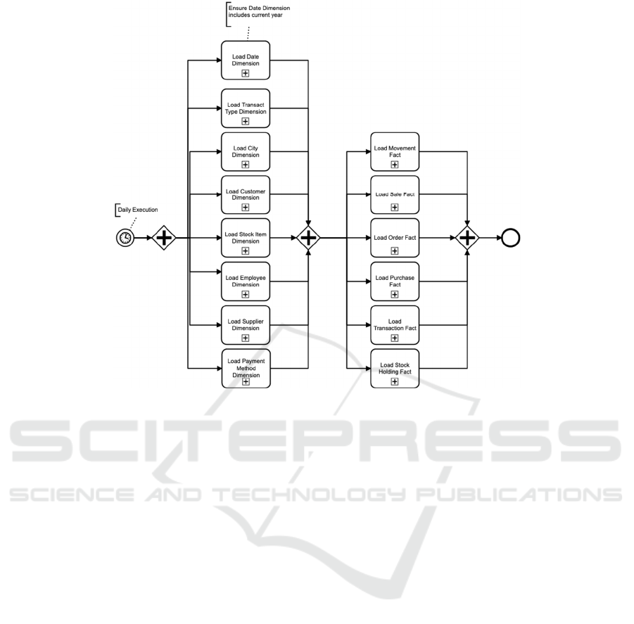
Figure 2: High-level ETL representation using BPMN.
3 BPMN FOR ETL
Understanding the data generated from business
processes and integrating them into the Data
Warehouse (DW) is very important to guarantee DW
conformity and identify potential data quality
problems. Using a common language such as the
BPMN can be valuable since it enhances
communication between business analysts, technical
developers, and business people (Akkaoui et al.,
2009).
BPMN provides three types of diagrams:
process/collaboration, choreography, and
conversation. The process/collaboration diagram
models the process flow using several BPMN
elements. It is also possible to represent one process
(process diagram) or the collaboration between two
or more processes with their exchanged messages
(collaboration diagram). The choreography diagram
allows for modelling the data exchanged between
partners. The main difference to collaboration
diagrams is that with choreography diagrams data
exchange is modelled as an activity. The conversation
diagram represents the involved partners (from
different domains) and their relationships.
The BPMN model presented in Figure 1 is based
on the Akkaoui et al. (2009) proposal, and can be
understood even with basic knowledge about process
modelling and ETL. The process begins with a start
event (represented an unfilled circle). The rounded
rectangles represent an activity. BPMN tasks such as
"Load Cities.txt" describe atomic tasks, while tasks
such as "Fill TempGeo.State" describe compound
tasks that can be detailed using another BPMN
diagram. The BPMN sub-processes also include a
Loop marker, i.e., an execution control mechanism to
repeat the ETL task's executions until a specific
condition evaluates False. The connecting arrows
between BPMN activities are used for describing the
sequence flow. The process contains a BPMN
gateway (the diamond shape). In this case, a Splitting
and Joining Parallel Gateway is used, meaning that
several parallel paths will be initiated and
synchronized before proceeding to the next step. The
gateway is "blocking" the process sequence flow until
the data from each data source (identified by BPMN
tasks) completes. Additionally, the process depicted
includes two intermediate events: Error Boundary
Event that interrupts the associated task, executing
the "Reject to bad data" activity; and a Compensation
Boundary Event that references a specific
compensation activity ("Load to ready data"). BPMN
artifacts and annotations are also used to describe
attribute values and additional information. It is
Using BPMN for ETL Conceptual Modelling: A Case Study
269
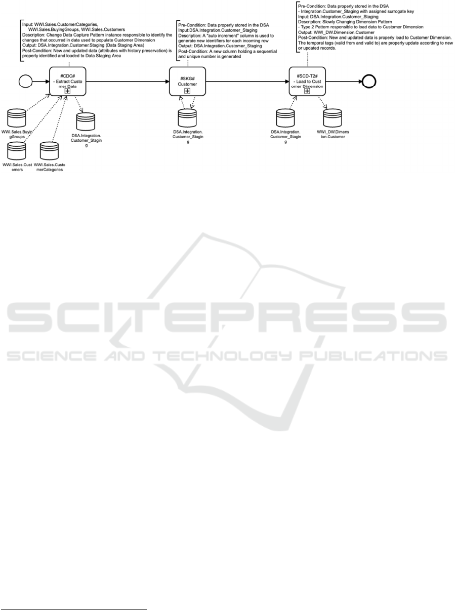
Figure 3: BPMN conceptual model with patterns representation.
possible to add informal expressions to activities and
gateways to define properties and conditions that
enrich semantics. Keywords such as: "Input",
"Output", "Parameters", or "Comments" can be used
for improving process readability. Noteworthy that
several BPMN elements defined in (Akkaoui et al.,
2009) are not presented in Figure 1.
4 THE CASE STUDY
12
To provide an overview and foster the discussion on
how BPMN can be used in more complex scenarios,
the Wide World Importers
3
(WWI) Microsoft ETL
example was selected. The WWI is a wholesale
novelty goods importer and distributor operating
from the San Francisco bay area. The DW is
composed of six "modules" referring to events
generated by specific business processes, which
results in several star schemas. For this work, we
selected the Sale schema ETL processes. This schema
integrates a "Sale" fact table representing invoiced
sales to customers, and the "Date", "City",
"Employee", "Customer", and "Stock Item"
dimensions. The ETL processes are implemented
using Microsoft Integration Services workflows.
An ETL conceptual model can be used as an
abstract view, contributing with metadata that can be
added to enrich the the ETL system. It is noteworthy
that an over-specification of conceptual models
(mainly considering the ETL context) can
compromise the process interpretation, turning
BPMN diagrams complex to read and understand
(Griethuysen, 2009).
1
2
3
https://docs.microsoft.com/en-us/sql/samples/wide-
world-importers-what-is?view=sql-server-ver15
Figure 2 illustrates an ETL conceptual model
representing the processes and execution order. This
case represents an abstract view of the processes
responsible for loading data to each DW dimension
and correspondent fact tables. This is one of the most
abstract representations that can be done over the
implemented process. This model followed some
design approaches:
Pools are not represented – Pools are especially
interesting for modelling collaboration,
representing several partners' interactions.
Data Annotations are reduced – They could be
included in every activity to improve process
readability; however, since each BPMN
subprocess is self-explanatory, this detail was
omitted.
Data artifacts were not used – Considering each
BPMN subprocess represents a coarser grain
component (potentially with several data
repositories involved), the number of data
artifacts can result in over-specification.
Only sub-processes were used – Only high-level
components are represented.
A timer start event was used – indicating the
process will execute with a given periodicity. A
data annotation was used to inform this ETL
process will execute daily.
Since dimensions need to be populated before the fact
tables (due to the existence of some referential
integrity constraints), they are grouped between
BPMN Parallel Gateways. The conceptual
representations presented till now are focused on the
control flow between the core ETL components.
DATA 2021 - 10th International Conference on Data Science, Technology and Applications
270
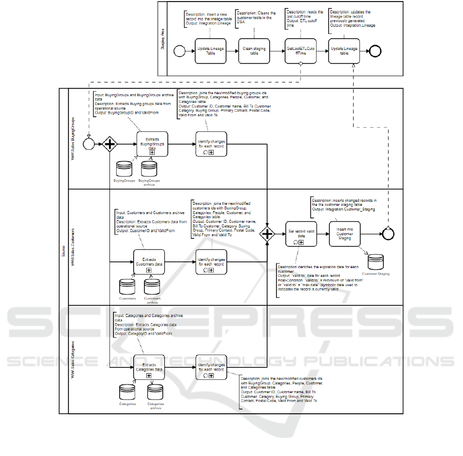
Figure 4: Elementary ETL process level.
In this case, the process is driven, considering the DW
tables that will be populated. This abstract
representation describes the main concepts and
process logic without referring to technical aspects.
Further detailed models can be created, providing a
hierarchical decomposition of the ETL process to
develop.
Using BPMN, processes can be modeled using
multiple abstraction levels. The main idea is to use
specific elements to add or remove detail to the
process. Thus, process understandability can be
adapted by hiding irrelevant information to a
particular development stage or even to a specific
user profile. BPMN sub-processes can be useful for
creating different abstraction levels and for
simplifying model representation (Reijers &
Mendling, 2010). Thus, a top-down modelling
approach can be followed for describing different
modelling perspectives. To illustrate the discussed
hierarchical decomposition, Figure 3 presents a
detailed view over the "Load Customer Dimension"
(Figure 2). This process is responsible for:
1) extracting data from each of the identified tables
needed for customer data load;
2) joining data according to the needs of the target
dimension;
3) storing the data in a data staging area (DSA)
table.
At this point, both BPMN sub-processes and atomic
tasks can be used. If a specific task is further
decomposed at a conceptual level, a sub-process
should be used; otherwise, a BPMN task should be
used. This conceptual layer is based on the Pattern-
Using BPMN for ETL Conceptual Modelling: A Case Study
271

Oriented Approach (Oliveira & Belo, 2012). In the
diagram presented in Figure 3, three patterns are used:
Change Data Capture (CDC) is used to detect
data changes in data sources.
Surrogate Key Generation (SKG) is used to
generate a surrogate key for each new row
coming from data sources.
Slowly Changing Dimensions (SCD) (type 2) is
used in the DW design for handling customer's
data history.
In Figure 3, we can see CDC and SCD patterns
represented as sub-processes, meaning that they will be
decomposed in the next BPMN conceptual layer. At
this abstraction layer, patterns are used for identifying
common ETL procedures to simplify the development.
Additionally, the ETL development complexity starts
to emerge, providing a high-level but descriptive view
of the efforts required to accomplish each task. This
ETL representation also includes BPMN Datastores to
visually represent the repositories involved in each
task, with the association arrow's directionality
indicating if they are used as input or output. Coupled
with each pattern, BPMN Data Annotations with a
specific data structure are used. The pre-condition
keyword indicates any requirements that can be used to
validate the execution of a particular task, input
indicates the data repositories in which data will be
extracted (prefixed as: database name(dot)schema
name(dot)table name), a description (as the name
suggest a textual description), the output indicating the
data repositories in which data will be loaded, and
finally, the post-condition block indicating the
conditions/rules that should be guaranteed to qualify
the pattern output as success/unsuccess.
Figure 4 presents a more granular view over a
"#CDC# Extract Customer Data" sub-process. A
collaboration diagram is used for modelling processes
framed within different "partners". Partners were
associated with each source data object, and DSA used
to support ETL execution. The "Staging Area" BPMN
pool represents all atomic tasks needed to support the
execution of the CDC procedure. In this scenario,
lineage keys are used to track ETL execution. The
"Lineage" table generates a new key for each record,
identifying the table that is being loaded with data, the
process starts and ends time, state
(successful/unsuccessful), and source system cut-off
time (that it is used to control the amount of data that is
transferred using the cut-off date in the past). The task
"Update Lineage Table" is used to store a new record
indicating the load process date registered for customer
dimension (this table will be updated when the process
finishes). Next, the "Clean Staging Table" truncates the
staging table used to store the extracted customer data
in the DSA (in each moment, this table only stores the
records handled for each DW load). The
"GetLastETLCutoffTime" task represents the
procedure responsible for getting the cut-off time
generated before starting the dimension and fact tables
loading process. Next, the subsequent populating
process is focused on the source system that holds all
the operational data needed to populate the Customer
dimension (and for that reason, it is represented in the
"Source" pool).
Message flows are exchanged between the
represented pools (the one representing source data
ETL activities and another representing the staging
area ETL activities). Each BPMN lane inside the
"Source" pool describes the process scoped within the
handled source table. The parallel gateway indicates
the tasks for loading data from each source table are
independent (they can be executed in parallel if the
physical architecture allows). For each source table,
BPMN sub-processes are used to describe the
extraction data processes from source data. A sub-
process is used for process representation since it can
be detailed in a more specific diagram. Two tables are
used: one referring to the current data and the other
one referring to the archived/historical data. A CDC
based on audit columns is used to identify all the
changes made since the last ETL execution (using the
lineage table) and the ETL cut-off time. Next, the
"Identify changes for each record" sub-process
represents the procedure responsible for building data
records from the modified BuyingGroups,
Customers, and Categories (joining each of the
respective tables from the source system). With all
changes identified, the "Set record valid Date" task
works out the expiration date by using the "Valid
From". The "Insert into Customer Staging" task is
used for representing the procedure responsible for
storing new/changed data into the customer staging
table. Finally, the lineage table is updated through the
"Update Lineage Table" task. Considering the example
from Figure 4, several decisions were made for this
abstraction layer, namely:
Use of BPMN collaboration diagram: since the
two data repositories (source repository and
DSA) are represented as separate
entities/partners, the collaboration diagrams
represent synchronized interactions supported by
exchanging messages between two or more
processes. Process diagrams can also be used. At
this conceptual level, the "Identify changes for
each record" and "Set record valid Date" sub-
processes can be drilled down, with their internal
tasks being modelled using a Process diagram.
DATA 2021 - 10th International Conference on Data Science, Technology and Applications
272

Collaboration diagrams help to document the co-
operation of several ETL components. As stated
in (Akkaoui et al., 2009), pools and lanes allow
ETL processes to be organized according to
several strategies, such as technical architecture,
user profile, or business entities.
Sub-processes are used for activities described
with more detail in other diagrams (mainly for
simplifying diagrams representation).
Datastores are still used at this conceptual level
for representing the repositories involved and the
communication direction with the respective
activity.
Data Annotations use the same format described
before. Description, Pre-conditions, Input,
Output, and Post-conditions keywords can be
used to provide a semi-structured way to
document BPMN activities.
The loop marker is used in some sub-processes
("Identify changes for each record" and "Set
record valid date") to indicate that the grain used
for describing the associated process is related to
each data instance/record.
Pools are included but are optional. If pools are
not crucial for understanding the process, they
should not be included in the diagram.
Intermediate events are not included in this
diagram. They can identify scenarios for handling
exceptions in ETL processes.
Table 1 presents an overview of the three different
abstraction layers. The first column identifies the level
at which ETL processes can be represented. The
Process level allows for an overview of the ETL
system's main processes directly related to each one of
the involved objects that should be populated. It can
represent only the dependencies between dimensions
and fact table population processes and describe sub-
processes related to each data object. For example, it
can be used to identify the need to apply an SCD
technique or to identify the constraints applied to the
use of bridge tables. This Process model can be used as
a top-down mechanism to develop other layers
progressively.
The Pattern level represents a set of predefined sub-
processes associated with a specific procedure
typically used in ETL development. The design team
can provide additional configurable components,
forming a pattern palette that must be included in the
project documentation. It provides a more
straightforward way for describing the main ETL
components without specifying how such procedures
will be implemented. For example, this level can
identify the need to apply a specific CDC or SCD
mechanism without detailing how it will be handled.
At this level, activities are documented for identifying
inputs, outputs, and potential error handling
approaches in a high-level view. Data objects are also
identified, revealing in more detail the complexity of
the ETL system and the specific techniques used (for
example, for CDC or SCD).
Finally, the Task level mainly represents BPMN
tasks describing the algorithm for implementing the
patterns identified in the Pattern level. The
representation tasks such as joins, projections or
selections can be used at a logical level to describe how
each pne of the tasks will be implemented.
Table 1: Summary of BPMN abstraction layer for ETL
conceptual modelling.
Abstraction
level
Purpose
Main BPMN
artifacts
Process
Representing system
abstraction and
providing process
dependencies
desc
r
iption.
Subprocesses are
used to represent
data flows for DW
populating
processes.
Pattern
Representing the macro
activities presented in
the ETL system
regarding extraction,
quality and load
tecnhiques.
Subprocesses
represent common
ETL procedures/sub
systems.
Task
Represent the
elementary level for
ETL representation
using (mainly) atomic
tasks. Processes are
represented in a row-
by
-row processing.
Task are a
predominant
modelling artifact
5 CONCLUSIONS
This paper presented a BPMN conceptual modelling
approach for modelling ETL processes using three
different abstraction layers. Due to BPMN
expressiveness, which can be very useful for ETL
representation, ETL conceptual models can
significantly vary since people have different ways of
thinking, which promote different ways of
representing the same ETL process. In the last years,
the experience we acquired shows us that ETL
modelling based on BPMN is focused on language
semantics rather than a methodology that can be used
to represent the ETL development at different stages.
This sometimes results in BPMN processes mixing
different detail levels, which sometimes difficult
process interpretation and understanding. For that
reason, the approach proposed represents ETL
conceptual modelling in different layers, each one
Using BPMN for ETL Conceptual Modelling: A Case Study
273

representing a different process detail, providing to
the ETL development team specific tools for
communicating at different ETL development phases.
Each layer represents a new detail level applied to a
specific construct described in the previous layer.
This contributes to a more agile development
approach since models can enrich system
requirements incrementally. To show how this
technique can be used, we explored a specific sub-
process from an ETL scenario. We show how the
ETL specificities can be represented at a conceptual
level for conceptualizing ETL processes in an
effective way.
As future work, we want to provide a complete
system specification for the WWI case study, explore
different ETL (and ELT) application scenarios,
discussing how this modelling approach can be
adapted for different types of data integration
projects. Additionally, we want also to explore
BPMN choreography and conversation diagrams for
ETL representation, which may help model systems
that rely on a service-oriented architecture.
ACKNOWLEDGEMENTS
This work has been supported by national funds
through FCT - Fundação para a Ciência e Tecnologia
through project UIDB/04728/2020.
REFERENCES
Aagesen, G., & Krogstie, J. (2015). BPMN 2.0 for
Modeling Business Processes. In Handbook on
Business Process Management 1 (pp. 219–250).
Springer Berlin Heidelberg. https://doi.org/10.1007/
978-3-642-45100-3_10
Akkaoui, Z. El, Zimanyi, E., El Akkaoui, Z., & Zimanyi, E.
(2009). Defining ETL worfklows using BPMN and
BPEL. Proceeding of the ACM Twelfth International
Workshop on Data Warehousing and OLAP DOLAP
09, 41–48. https://doi.org/10.1145/1651291.1651299
Biswas, N., Chattapadhyay, S., Mahapatra, G., Chatterjee,
S., & Mondal, K. C. (2019). A new approach for
conceptual extraction-transformation-loading process
modeling. International Journal of Ambient Computing
and Intelligence, 10(1), 30–45. https://doi.org/
10.4018/IJACI.2019010102
Biswas, N., Chattopadhyay, S., & Mahapatra, G. (2017).
SysML Based Conceptual ETL Process Modeling.
International Conference on Computational
Intelligence, Communications, and Business Analytics,
242--255. https://doi.org/10.1007/978-981-10-6430-2
Dupor, S., & Jovanovi, V. (2014). An approach to
conceptual modelling of ETL processes. 37th
International Convention on Information and
Communication Technology, Electronics and
Microelectronics (MIPRO). https://doi.org/10.1109/
MIPRO.2014.6859801
El Akkaoui, Z., Mazón, J.-N. N., Vaisman, A., & Zimányi,
E. (2012). BPMN-Based Conceptual Modeling of ETL
Processes. Lecture Notes in Computer Science (Including
Subseries Lecture Notes in Artificial Intelligence and
Lecture Notes in Bioinformatics), 7448, 1–14.
https://doi.org/10.1007/978-3-642-32584-7_1
El Akkaoui, Z., Zimànyi, E., Mazón, J.-N., Trujillo, J.,
Akkaoui, Z. El, Zimànyi, E., Mazón, J.-N., & Trujillo,
J. (2011). A Model-driven Framework for ETL Process
Development. Proceedings of the ACM 14th
International Workshop on Data Warehousing and
OLAP (DOLAP’11), 45–52. https://doi.org/10.1145/
2064676.2064685
Griethuysen, J. J. Van. (2009). The Orange Report ISO
TR9007 (1982 - 1987) Grandparent of the Business
Rules Approach and SBVR Part 2 - The Seven Very
Fundamental Principles. Business Rules Journal, 10(5).
Kabiri, A., & Chiadmi, D. (2013). Survey on ETL
processes. Journal of Theoretical and Applied
Information Technology, 54(2), 219–229.
Oliveira, B., & Belo, O. (2012). BPMN Patterns for ETL
Conceptual Modelling and Validation. The 20th
International Symposium on Methodologies for
Intelligent Systems: Lecture Notes in Artificial
Intelligence, 7661 LNAI, 445–454. https://doi.org/
10.1007/978-3-642-34624-8_50
Oliveira, B., & Belo, O. (2015). Task Clustering on ETL
Systems - A Pattern-Oriented Approach. In A. Helfert,
MarkusHolzinger, O. Belo, & C. Francalanci (Eds.), 4th
International Conference on Data Management
Technologies and Applications (DATA‘2015) (pp. 207–
214). Springer International Publishing. https://doi.org/
10.1007/978-3-319-30162-4
Raj, A., Bosch, J., Olsson, H. H., & Wang, T. J. (2020).
Modelling Data Pipelines. 46th Euromicro Conference
on Software Engineering and Advanced Applications,
SEAA, 13–20. https://doi.org/10.1109/SEAA5122
4.2020.00014
Reijers, H. A., & Mendling, J. (2010). On the Usefulness of
Subprocesses in Business Process Models.
Simitsis, A., & Vassiliadis, P. (2003). A Methodology for
the Conceptual Modeling of ETL Processes. In J. Eder
& M. Missikoff (Eds.), CAiSE’03: Proceedings of the
15th International Conference on Advanced
Information Systems Engineering (pp. 305–316).
Springer-Verlag.
Trujillo, J., & Luj, S. (2003). A UML Based Approach for
Modeling ETL Processes in Data Warehouses. 307–
320.
Vassiliadis, P., Simitsis, A., & Skiadopoulos, S. (2002).
Conceptual modeling for ETL processes. Proceedings
of the 5th ACM International Workshop on Data
Warehousing and OLAP - DOLAP ’02, 14–21.
https://doi.org/10.1145/583890.583893.
DATA 2021 - 10th International Conference on Data Science, Technology and Applications
274
