
Designing and Implementing Software Systems using User-defined
Design Patterns
Mert Ozkaya
1
and Mehmet Alp Kose
2
1
Department of Computer Engineering, Yeditepe University, Istanbul, Turkey
2
Altinbas University, Institute of Graduate Studies, Istanbul, Turkey
Keywords:
Design Pattern Definition, Pattern-Centric Modeling, Code Generation, UML.
Abstract:
Software design patterns are the design-level solutions for the commonly occurring problems in software
development. Design patterns are applied in many industries where problems repeat with slight changes,
and applying the same solution that is proven to be quality reduces the development time and maximises the
software re-use. DesPat is a modeling toolset that offers a modeling notation set based on UML’s class diagram
for the users to design their software systems using the well-known 6 design patterns proposed by Gamma et al.
(abstract factory, singleton, composite, observer, visitor, and facade). DesPat also supports the combinations of
different pattern models for any software system, analysis of the pattern-centric models, and their automated
generation into Java skeleton code. In this paper, we extend DesPat with a new toolset that enables users
to define their own patterns. A pattern is defined with the types of components, component interfaces, and
relationships (i.e., generalisation, dependency, realisation, and composition). Any pattern definitions can then
be imported into the DesPat modeling toolset, through which one may specify software design models in
accordance with the pattern definitions, check the models against the pattern rules, and transform their models
in Java. We illustrate our extension with the gas station case-study.
1 INTRODUCTION
The notion of patterns has been initiated by Christo-
pher Alexander in the seventies, who is a famous ar-
chitect and considered the use of patterns for con-
structing buildings. According to Alexander, many
buildings essentially include the applications of the
same or similar solutions (i.e., patterns) and this al-
ways lead to the buildings with beautiful architectures
(Alexander, 1979; Alexander et al., 1975). Alexan-
der published a seminal book, discussing 253 differ-
ent patterns in terms of the problems and solutions
that can be applied on the buildings, constructions,
and towns (Alexander et al., 1977). A pattern essen-
tially addresses a problem that are come across many
times in different constructions and proposes an effec-
tive solution that leads to the beautiful architecture.
In the mid-nineties, patterns have been considered to
be applied for the software development to maximise
the quality of the software to be developed by re-
using the tested and proven high-quality design de-
cisions while minimising the development cost. Soft-
ware design patterns have first been considered sys-
tematically by Gamma et al.’s seminal book (Gamma
et al., 1994), which has been shown great interest by
both the academia and industry. Gamma et al. essen-
tially proposed 23 different software design patterns
which are categorised into three groups: structural,
creational, and behavioural patterns. The structural
patterns are concerned with composing large software
systems out of smaller and simpler system compo-
nents. The creational patterns are concerned with con-
trolling the creation of the components composing the
software systems. The behavioural patterns are con-
cerned with how the components composing software
systems should behave and interact with each other.
While many software development frameworks
have been existing today, they do not aid in using de-
sign patterns at code level. Also, as discussed in Sec-
tion 2, many design approaches have been proposed,
which do not however provide adequate level of sup-
port for defining patterns, specifying pattern-centric
models, checking their conformances, and generating
code. So, we initially proposed a modeling toolset
called DesPat (Ozkaya. and Kose., 2021), which en-
ables to design software systems using Gamma et al.’s
six design patterns that are believed to be among the
top-used design patterns in industry (Zhang and Bud-
Ozkaya, M. and Kose, M.
Designing and Implementing Software Systems using User-defined Design Patterns.
DOI: 10.5220/0010571404970504
In Proceedings of the 16th International Conference on Software Technologies (ICSOFT 2021), pages 497-504
ISBN: 978-989-758-523-4
Copyright
c
2021 by SCITEPRESS – Science and Technology Publications, Lda. All rights reserved
497

gen, 2013). These are the abstract factory, single-
ton, composition, facade, observer, and visitor pat-
terns. DesPat offers a graphical notation set for each
pattern type that is based on UML’s class diagram
(Rumbaugh et al., 2004). DesPat enables to specify
for any software system the pattern-centric models
that can be combined by re-using the same compo-
nents across different models. DesPat is supported
with a modeling editor that has been developed us-
ing the Metaedit+ meta-modeling tool (Kelly et al.,
2013). With DesPat’s modeling editor, users may
specify pattern-centric models, analyse them against
the pattern rules, and produce Java skeleton code.
However, DesPat in its current form supports a
pre-defined list of patterns, which prevents users from
defining their own solution domain and specifying
models in that domain. So, in this paper, we propose
an extension to DesPat for enabling users to define
new patterns, specify pattern-centric models, and gen-
erate software code from their models. We developed
a tool extension that provides users with an easy-to-
use graphical user interface (GUI) for defining pat-
terns in terms of component and interface types and
their relationships. The extension tool transforms the
pattern definitions into a meta-model in the context of
DesPat that can be accepted in the Metaedit+ meta-
modeling environment. The transformed meta-model
herein not only includes the mapping into the DesPat
notation set but also the rule definitions and transla-
tion algorithms in Java. So, upon importing a pattern
definition into Metaedit+, one may obtain a modeling
editor in Metaedit+ automatically, use the editor for
specifying pattern-centric software models, checking
the models for the pattern rules, and producing Java
skeleton code automatically.
2 RELATED WORK
The literature includes several software modeling and
design languages that can be used for designing soft-
ware systems and performing useful operations (e.g.,
formal verification and code generation) before im-
plementation. UML, for instance, has been consid-
ered as one of the top-used general-purpose design
languages (Ozkaya, 2018b; Malavolta et al., 2012),
which is supported with several tools and can be ex-
tensible via its extension mechanism (Ozkaya, 2019;
Ozkaya, 2018a). While UML and its derivatives may
be used for specifying pattern-centric software mod-
els, none of them enables pattern-specific operations
such as checking their pattern conformance and gen-
erating pattern-specific code. Moreover, combining
patterns (e.g., the system components playing differ-
ent roles in different pattern models) and defining new
patterns and using those definitions for designing soft-
ware systems are not inside their scope either. Many
other attempts, e.g., (Kim, 2015; Mak et al., 2004;
Mapelsden et al., 2002; Hedin, 1997; Nicholson et al.,
2009; Taibi and Ling, 2003; Mikkonen, 1998; Saeki,
2000), have been made towards the pattern definitions
and specifications. Those approaches are essentially
concerned with defining and using patterns for soft-
ware design, combining patterns, checking the pat-
tern conformances, verifying code against patterns,
and formally verifying the pattern models. However,
many of those approaches do not provide an up-to-
date tool support that is available for use and thus re-
main as the proof-of-concept only. Also, those that
support formal verification for the analysis of mod-
els require steep learning curve for many practition-
ers as a process algebra based notation set is imposed
(Malavolta et al., 2012). Besides, the existing ap-
proaches require precise syntax and semantics to be
used for defining patterns. While this is important for
processing the definitions, novice practitioners find
precise notations hard to use for quickly experiment-
ing with defining patterns. Our approach discussed in
this paper provides a graphical user interface that en-
ables users to simply define the component/interface
types and their relationships via some dialog boxes,
lists, and menus without having to learn any pattern
definition notations. We also enable the transforma-
tion of pattern definitions into precise meta-model.
3 OVERVIEW OF DesPat
DesPat offers a graphical modeling notation set for
each design pattern supported, depicted in Figure 1.
DesPat’s notation set is inspired from UML’s class
diagram (Rumbaugh et al., 2004), which many practi-
tioners are familiar with (Ozkaya, 2018b; Malavolta
et al., 2012). DesPat’s notation set for each pat-
tern consists of a set of elements and their relation-
ships. An element may be a component or an in-
terface, where the former represents the composing
unit of a software system and the latter represents the
points of interaction for the components. Concerning
the relationships, the interface realisation relationship
is for specifying for a component the interface(s) that
the component realises and each consists of the oper-
ations provided in the component’s environment. The
generalisation relationship is for specifying the com-
monalities among different components. The depen-
dency relationship is for specifying which component
may send/receive message to/from which other com-
ponents. Note that a component may be dependent
ICSOFT 2021 - 16th International Conference on Software Technologies
498
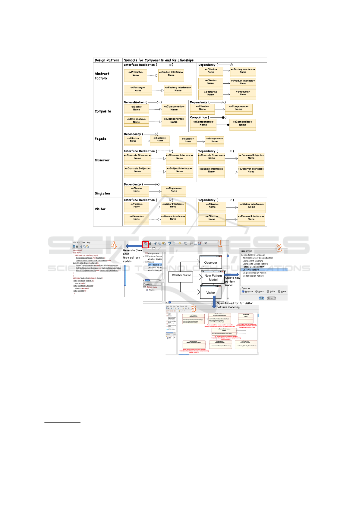
Figure 1: DesPat’s notation set.
Figure 2: DesPat’s modeling editor.
on an interface of some component. The composi-
tion relationship is for specifying the whole-part rela-
tionship between components where one component
is composed of some other component(s).
Figure 2 depicts DesPat’s modeling toolset
1
. So,
users firstly specify for any software system under de-
sign a boxes&lines diagram as depicted in the edi-
1
DesPat’s web-site: https://sites.google.com/view/despat
tor (1), where a component representing the system is
linked with a set of boxes each representing a differ-
ent pattern model. Users may right-click on a pattern
model box, which opens up a new dialog box as de-
picted in (2) for choosing one of the pattern types sup-
ported by DesPat. This prompts a new sub-editor as
depicted in (3) where users specify the pattern mod-
els using DesPat’s notation set for the correspond-
ing pattern. Lastly, users may click on the icon de-
Designing and Implementing Software Systems using User-defined Design Patterns
499
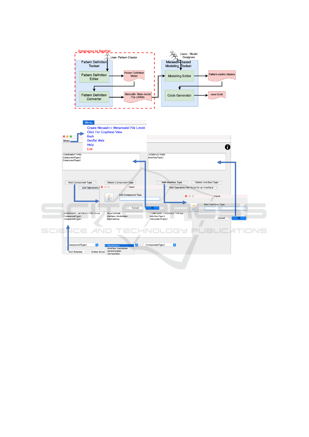
Figure 3: DesPat’s extended tool architecture.
Figure 4: Defining a design pattern via the pattern definition editor.
picted in (4) to generate a Java implementation from
the pattern model(s) of the software system under de-
sign. Note that in (3), the pattern model includes red-
colored texts that are the warning messages which are
generated automatically at modeling time when the
pattern models violate the pattern rules.
4 DEFINING DESIGN PATTERNS
As depicted in Figure 3, DesPat’s modeling toolset
has been extended with a pattern definition toolset,
whose goal is to let users define new patterns that can
be used via DesPat’s modeling toolset for specifying
software design models in accordance with the pattern
rules and produce Java implementation automatically.
The pattern definition toolset includes an editor
and converter, which have been developed in Java
and are each supported with a graphical user interface
(GUI). The toolset can be downloaded as a standalone
jar file via DesPat’s project web-site
1
.
4.1 Pattern Definition Editor
The pattern definition editor is accessible via a GUI
that offers a menu for the following activities: (i)
opening an existing pattern definition, (ii) creating a
pattern definition, (iii) browsing DesPat’s webpage,
and (iv) opening the user manual document.
Upon choosing to create a new pattern defini-
tion, a GUI that is depicted in Figure 4 is displayed,
through which users define the component and inter-
face types and relationships between the component
and interface types. We consider four types of rela-
tionships that are supported by DesPat and discussed
ICSOFT 2021 - 16th International Conference on Software Technologies
500
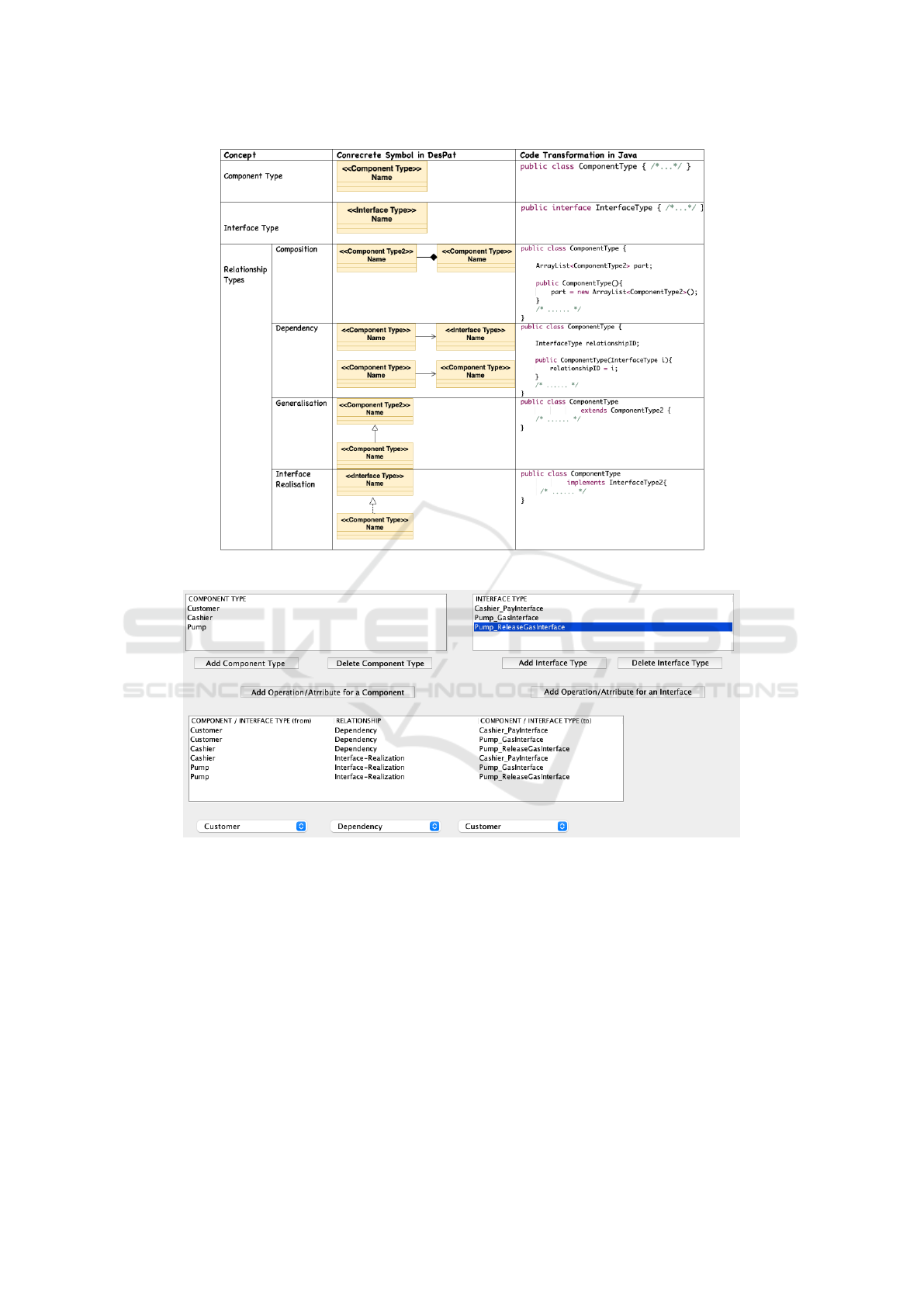
Figure 5: Mapping pattern definition concepts with DesPat’s meta-model (concrete symbols and Java transformation).
Figure 6: The gas station pattern definition via the pattern definition editor.
in Section 3, which are interface realisation, compo-
sition, generalisation, and dependency. So, to use any
pattern defined, a software system needs to be struc-
tured in terms of those components and interfaces in
a way that meets the relationship constraints. For any
component/interface type, one may also define the at-
tributes and operations. Whenever a component/inter-
face type is selected via the GUI and the correspond-
ing button (e.g., add operation) is clicked in Figure 4,
a new GUI appears for defining the operations/at-
tributes. While operations are defined in terms of their
return type, name, and parameter lists, attributes are
defined in terms of name and default value.
Opening an existing pattern definition is per-
formed via another GUI (similar to Figure 4) that en-
ables to choose one of the existing patterns and ed-
it/delete the existing component/interface type(s) and
relationship type(s) of the chosen pattern definition.
For any pattern definition opened/created, one
may click from the menu of the corresponding GUI
(see “Menu” in Figure 4) to export the pattern defini-
tion into a Metaedit+ meta-model file as discussed in
the next sub-section. Also, one may click from menu
to display the graphical visualisation of the pattern
definition, which opens up a UML class diagram that
describe the component and interface types and their
Designing and Implementing Software Systems using User-defined Design Patterns
501

relationships. So, this may help in understanding and
communicating the pattern definitions.
Lastly, any patterns created are stored persis-
tently on the user machine using the SQLite library
2
,
through which the patterns may be accessed and
edited later via the ”open” activity.
4.2 Pattern Definition Converter
The pattern definition converter works as integrated
with the pattern definition editor. Indeed, one may
run the converter by clicking from the menu of the
open/create GUIs, as discussed above. Given any pat-
tern definition created via the editor, the converter
produces a meta-model definition for the Metaedit+
environment. The produced meta-model is in the
.mxt XML file format, which can be imported in
Metaedit+. The meta-model here includes (i) the
mapping of the concepts and relationships defined in
the pattern into the concrete symbols in the DesPat
notation set introduced in Section 3, (ii) the defini-
tions of the warnings that are raised upon the viola-
tions of the pattern relationships, and (iii) the code-
generator definition for producing Java skeleton code
from any given model that satisfies the pattern def-
inition. Figure 5 essentially shows how the pattern
definition concepts are mapped in DesPat and trans-
formed in Java.
Upon importing the produced meta-model file in
Metaedit+, a Metaedit+-based modeling editor is ob-
tained automatically for specifying software design
models in accordance with the pattern definition. The
modeling editor herein enables for checking models
against the pattern definitions at modeling time and
raise any violations (e.g., missing relationships miss-
ing concepts) with precise warning messages. The
modeling editor is also integrated with a code genera-
tor that is produced from the Java mapping embedded
inside the meta-model file. The code generator herein
can be used for generating a Java skeleton code from
any model specified with the editor.
5 CASE-STUDY: GAS STATIONS
To illustrate DesPat’s extension, we consider defin-
ing a pattern for the gas station systems (Naumovich
et al., 1997). Any gas station systems may be repre-
sented with different configurations, while each sys-
tem is expected to have a varying number of instances
of the same types of components that interact with
each other under certain protocols. So, the pattern
2
SQLite: https://sqlite.org/
definition imposes three types of components – cus-
tomer, cashier, and pump. Each customer makes a
payment request to a cashier and then makes a gas
request to a pump. Upon receiving the payment re-
quest, the cashier may make a release-gas request to
pump for that customer. The pump may then accept
the customer’s gas request.
5.1 Meta-model Definition
Figure 6 shows the gas station pattern defined via
the pattern definition editor. Therein, the customer,
cashier, and pump component types and also a set of
interface types are defined. As specified for the re-
lationships, components interact with each other via
interfaces. So, cashier realises a customer-interface
which is used by the customers to send payment re-
quests to cashiers. Pump realises a cashier-interface
which is used by the cashiers to request pump to re-
lease gas for the customers who already made the pay-
ment. Pump also realises a customer-interface which
is used by the customers to request gas after payment.
We also defined some operations for the inter-
face types. Cashier’s cashier-interface includes the
pay operation for making payment, pump’s customer-
interface includes the gas operation for receiving gas
request, and pump’s cashier-interface includes the re-
leaseGas operation for receiving gas-release request.
5.2 Model Specifications
We used the pattern converter to obtain a modeling
editor in Metaedit+ for our pattern definition. Us-
ing the modeling editor, we specified the gas station
model shown in Figure 7, which consists of two cus-
tomers, one cashier, and one pump that interact with
each other in accordance with the pattern relationship
rules. Note that the interface operations depicted are
essentially the operations defined in the pattern and
thus come with the interface specifications by default.
In Figure 8, we added a new customer compo-
nent to the same configuration (i.e., cust3), and the
modeling editor indicates warning messages (shown
with red-colored texts). The warning herein is due to
that the dependency relationships defined in the pat-
tern are not satisfied with cust3. Indeed, cust3 needs
to be related to the CashierInterface and PumpInter-
face Cust, as defined in the pattern in Figure 6.
5.3 Model Transformation
Having specified the gas station model depicted in
Figure 7 in accordance with the pattern definition
given in Figure 6, we used the code generation tool
ICSOFT 2021 - 16th International Conference on Software Technologies
502
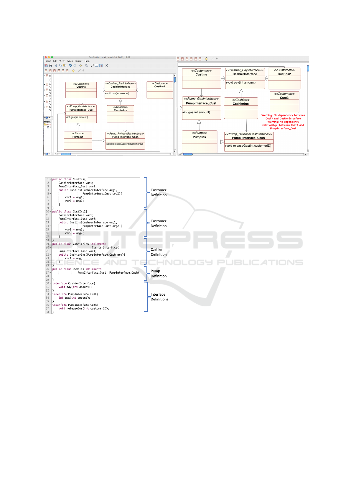
Figure 7: The gas station specification in Metaedit+. Figure 8: Detecting pattern rule violation at modeling time.
Figure 9: The Java skeleton code transformed from the gas
station specification in Metaedit+.
integrated with the modeling editor and obtained the
Java skeleton code in Figure 9. So, the Java skele-
ton code includes a separate class definition for each
component and an interface definition for each inter-
face specified in the gas station model. Note that
the definition of a class that depends on some other
class/interface includes a variable for storing a ref-
erence to the dependent class/interface. Indeed, cus-
tomer includes variables for sending method-calls to
the cashier and pump components over their inter-
faces and cashier includes a variable for the pump
interface. Also, the interface definitions include the
method definitions as specified in the (meta-)model.
ACKNOWLEDGEMENT
This work was supported by a project of the Scien-
tific and Technological Research Council of Turkey
(TUBITAK) under grant 120E144.
6 CONCLUSIONS
DesPat has been proposed for specifying software de-
sign models using Gamma et al.’s six well-known de-
sign patterns, which are composite, singleton, visitor,
observer, abstract factory, and facade. DesPat offers a
graphical notation set inspired from UML’s class dia-
gram, which is believed to be familiar to many prac-
titioners in industry. So, given any software system
under design, users may use the DesPat modeling ed-
itor to draw class diagrams for different patterns sup-
ported, combine the pattern models by re-using the
same components (i.e., classes) in different pattern
models, and analyse the pattern models according to
the pattern rules at modeling time. DesPat’s model-
ing toolset also transforms the pattern models of any
software system into Java skeleton code.
In this paper, we introduced an extension to
DesPat for the capability of specifying software de-
sign models according to the user-defined patterns.
We developed a toolset that enables for defining soft-
ware design patterns in terms of the component and
interface types, and the relationships between them.
So, any software system can be designed by using
as many instances of the component and interface
types as needed in a way that satisfies the relationship
rules. We also developed a converter that takes any
pattern definition and produces the meta-model file in
XML which can be imported in the Metaedit+ meta-
Designing and Implementing Software Systems using User-defined Design Patterns
503

modeling environment. Metaedit+ then provides a
modeling editor for specifying pattern-centric mod-
els, analysing models, and generating Java skeleton
code. We illustrated our extension toolset with the
well-known gas station system architecture.
In the future, we will improve our pattern defini-
tion notation to support different aspects of software
design such as the behaviour and interaction. We will
also extend DesPat so as to enable the isolated com-
ponents that are not involved in any pattern to be spec-
ified as part of the system design and interact with the
components of the pattern-centric models and other
isolated components.
REFERENCES
Alexander, C. (1979). The Timeless Way of Building. Ox-
ford University Press.
Alexander, C., Ishikawa, S., Silverstein, M., Jacobson, M.,
Fiksdahl-King, I., and Angel, S. (1977). A Pattern
Language: Towns, Buildings, Construction. Center
for Environmental Structure (Book 2). Oxford Univer-
sity Press.
Alexander, C., Silverstein, M., Angel, S., Ishikawa, S., and
Abrams, D. (1975). The Oregon Experiment. Oxford
University Press, New York.
Gamma, E., Helm, R., Johnson, R., and Vlissides, J.
(1994). Design patterns: Elements of reusable object-
oriented software. Addison Wesley. ISBN-13: 978-
0201633610.
Hedin, G. (1997). Language support for design patterns
using attribute extension. In Bosch, J. and Mitchell,
S., editors, Object-Oriented Technology, ECOOP’97
Workshop Reader, ECOOP’97 Workshops, Jyv
¨
askyl
¨
a,
Finland, June 9-13, 1997, volume 1357 of Lecture
Notes in Computer Science, pages 137–140. Springer.
Kelly, S., Lyytinen, K., and Rossi, M. (2013). Metaedit+
A fully configurable multi-user and multi-tool CASE
and CAME environment. In Jr., J. A. B., Krogstie,
J., Pastor, O., Pernici, B., Rolland, C., and Sølvberg,
A., editors, Seminal Contributions to Information Sys-
tems Engineering, 25 Years of CAiSE, pages 109–129.
Springer.
Kim, D. (2015). Design pattern based model transformation
with tool support. Softw. Pract. Exp., 45(4):473–499.
Mak, J. K. H., Choy, C. S. T., and Lun, D. P. K. (2004).
Precise modeling of design patterns in uml. In Pro-
ceedings. 26th International Conference on Software
Engineering, pages 252–261.
Malavolta, I., Lago, P., Muccini, H., Pelliccione, P., and
Tang, A. (2012). What industry needs from architec-
tural languages: A survey. IEEE Transactions on Soft-
ware Engineering, 99.
Mapelsden, D., Hosking, J., and Grundy, J. (2002). De-
sign pattern modelling and instantiation using dpml.
In Proceedings of the Fortieth International Confer-
ence on Tools Pacific: Objects for Internet, Mobile
and Embedded Applications, CRPIT ’02, page 3–11,
AUS. Australian Computer Society, Inc.
Mikkonen, T. (1998). Formalizing design patterns. In Torii,
K., Futatsugi, K., and Kemmerer, R. A., editors, Forg-
ing New Links, Proceedings of the 1998 International
Conference on Software Engineering, ICSE 98, Kyoto,
Japan, April 19-25, 1998, pages 115–124. IEEE Com-
puter Society.
Naumovich, G., Avrunin, G. S., Clarke, L. A., and Oster-
weil, L. J. (1997). Applying static analysis to software
architectures. In Jazayeri, M. and Schauer, H., editors,
ESEC / SIGSOFT FSE, volume 1301 of Lecture Notes
in Computer Science, pages 77–93. Springer.
Nicholson, J., Gasparis, E., Eden, A. H., and Kazman, R.
(2009). Verification of design patterns with lepus3.
In Denney, E., Giannakopoulou, D., and Pasareanu,
C. S., editors, First NASA Formal Methods Symposium
- NFM 2009, Moffett Field, California, USA, April
6-8, 2009, volume NASA/CP-2009-215407 of NASA
Conference Proceedings, pages 76–85.
Ozkaya, M. (2018a). Analysing uml-based software mod-
elling languages. Journal of Aeronautics and Space
Technologies, 11(2):119–134.
Ozkaya, M. (2018b). Do the informal & formal software
modeling notations satisfy practitioners for software
architecture modeling? Information & Software Tech-
nology, 95:15–33.
Ozkaya, M. (2019). Are the UML modelling tools power-
ful enough for practitioners? A literature review. IET
Softw., 13(5):338–354.
Ozkaya., M. and Kose., M. (2021). Despat: A modeling
toolset for designing and implementing software sys-
tems using design patterns. In Proceedings of the 16th
International Conference on Evaluation of Novel Ap-
proaches to Software Engineering - ENASE,, pages
251–260. INSTICC, SciTePress.
Rumbaugh, J., Jacobson, I., and Booch, G. (2004). Uni-
fied Modeling Language Reference Manual, The (2Nd
Edition). Pearson Higher Education.
Saeki, M. (2000). Behavioral specification of GOF design
patterns with LOTOS. In 7th Asia-Pacific Software
Engineering Conference (APSEC 2000), 5-8 Decem-
ber 2000, Singapore, pages 408–415. IEEE Computer
Society.
Taibi, T. and Ling, D. N. C. (2003). Formal specification
of design pattern combination using BPSL. Inf. Softw.
Technol., 45(3):157–170.
Zhang, C. and Budgen, D. (2013). A survey of experienced
user perceptions about software design patterns. Inf.
Softw. Technol., 55(5):822–835.
ICSOFT 2021 - 16th International Conference on Software Technologies
504
