
Evaluation of the Capabilities of a Hybrid Driven Exoskeleton in
Passive Mode of Interaction
Dimitar Chakarov
a
, Ivanka Veneva
b
, Pavel Venev
c
and Mihail Tsveov
d
Institute of Mechanics, Bulgarian Academy of Sciences, “Acad. G. Bonchev” str., Block 4, Sofia 1113, Bulgaria
Keywords: Exoskeleton Arm, Electric Motors, Pneumatic Cylinders, Interaction Force, Patient, Harmonic Motion,
Mechanical Impedance, Experiments, Simulations.
Abstract: A new construction of upper limbs exoskeleton with hybrid drive was studied in this work. The paper presents
mechanical structure and actuation of exoskeleton with hybrid drive including pneumatic cylinders and
electric motors. In order to evaluate the transparency and safety, the capabilities of the exoskeleton in passive
mode of interaction was estimated. A model of the interaction force between the patient and the exoskeleton
arm in passive mode was built. The model was based on harmonious movements imposed in one joint of the
exoskeleton arm. Experiments and simulations were performed to assess the interaction force between the
patient and the exoskeleton because of the mechanical impedance of the device. The force of interaction was
obtained from passive forces, such as inertial, frictional and gravitational forces, as well as from the elasticity
of the pneumatics. The patient-initiated harmonic motion was studied in two cases- without pressure in the
chambers and with pressure for gravity compensation. The results where demonstrated graphically.
Conclusions where made about the behavior of the exoskeleton in the passive mode of interaction.
1 INTRODUCTION
Robotic rehabilitation using exoskeletons is an
alternative to conventional manual therapy to
improve motor function in post-stroke patients
(Manna, 2018). The rehabilitation exoskeleton
(Jarrasse, 2014) should be able to create a great force
for assisting and directing the patient's hand in the
early stages of recovery, as well as following the
human hand without opposition or being able to react
to any movement made by the patient in the full stage
of recovery. In the control design of the rehabilitation
exoskeleton in general, two "extreme" ideal regimens
can be defined, covering the entire spectrum of
therapeutic interventions: "robot in charge" and
"patient in charge" (Veneman, 2006).
In the "robot in charge" regime, it is important that
the robot has enough strength and power to realize the
desired movement with a relatively high impedance.
In a "patient in charge" it is important that the forces
of interaction between the exoskeleton and the patient
a
https://orcid.org/0000-0002-2312-5725
b
https://orcid.org/0000-0001-5501-7668
c
https://orcid.org/0000-0001-7809-3540
d
https://orcid.org/0000-0001-5051-4411
are low; in other words, the perceived impedance of
the robot should be low. The main feature here is
transparency.
There are two main approaches to reducing the
mechanical impedance of the rehabilitation
exoskeletons and to ensure security and transparency
in interaction: active and passive. Electric motors,
pneumatic, hydraulic and other active drives are used
to reducing the impedance and to control the contact
force through an active approach. The active
approach is based on sensors and algorithms for
motor control. There are two methods to control the
contact force: direct and indirect. In the direct
approach, the controller regulates the force with a
control loop and using force feedback of the
measurement and desired value of the force
(Ansarieshlaghi, 2019). Indirect force control
methods are known as impedance or admittance
(Hogan, 1985). Impedance controlled systems detect
the deviation in position and control the force applied
by the device, while admittance controlled systems
442
Chakarov, D., Veneva, I., Venev, P. and Tsveov, M.
Evaluation of the Capabilities of a Hybrid Driven Exoskeleton in Passive Mode of Interaction.
DOI: 10.5220/0010569004420449
In Proceedings of the 18th International Conference on Informatics in Control, Automation and Robotics (ICINCO 2021), pages 442-449
ISBN: 978-989-758-522-7
Copyright
c
2021 by SCITEPRESS – Science and Technology Publications, Lda. All rights reserved
detect the contact force and control the position and
velocity or the device.
The passive approach involves passive or
inherently safe drives. The pneumatic actuation
allows force control according to the active
approach. Also, pneumatic actuation has a natural
flexibility and allows to achieve inherent safety and
transparency in the process of rehabilitation in a
passive way (Morales, 2011). Due to the inherent
natural compliance of air and its storage in closed
chambers, pneumatic actuation can create passive
support force.
There are three types of pneumatic drives:
pneumatic cylinders, pneumatic artificial muscles
(PAM) and rotating pneumatic motors. High natural
compliance and non-linearity of air compression of
pneumatic drives result in a low dynamic force
response, which limits the efficiency of the actuator.
To take advantage of pneumatic actuators while
reducing their shortcomings, they are combined with
electric drives. (Rouzbeh, 2019) integrates a low
friction pneumatic cylinder and a rotating electric
motor into a compact device. A similar design of
hybrid propulsion including a linear electric motor
and pneumatic cylinder is presented in (Nakata,
2015). The hybrid pneumatic and electric actuator,
compared to high-gear electric drive, produces a
lower impedance while maintaining a high driving
force value.
A pneumatically driven exoskeleton for training
and rehabilitation, aided by interactions in virtual
scenes, was developed by the authors. PAM bundles
included in an antagonistic circuit are used for
propulsion. In order to overcome the shortcomings
of pneumatic muscles, the possibilities of using a
hybrid drive involving a pair of PAM bundles and a
parallel working DC motor are explored (Chakarov,
2019). The structure of the exoskeleton is further
developed with hybrid drive, integrating pneumatic
cylinders and electric motors.
The subject of the present work is the study of
the mechanical structure and the actuation of the
hybrid exoskeleton with pneumatic cylinders and
electric motors. The aim of this study is to evaluate
the transparency and safety by assessing the
interaction force between the patient and the
exoskeleton in passive mode. Experiments and
simulations for estimating the interaction force
which is a result of the mechanical impedance of the
device are object of the present work.
2 MECHANICAL DESIGN AND
ACTUATION OF THE UPPER
LIMBS EXOSKELETON
To design a rehabilitation exoskeleton of the upper
limbs, which provides transparency and natural
safety, it is necessary to build a structure with low
values of mechanical impedance. This means that the
exoskeleton has extremely light segments attached to
the limbs and all heavy components are placed on the
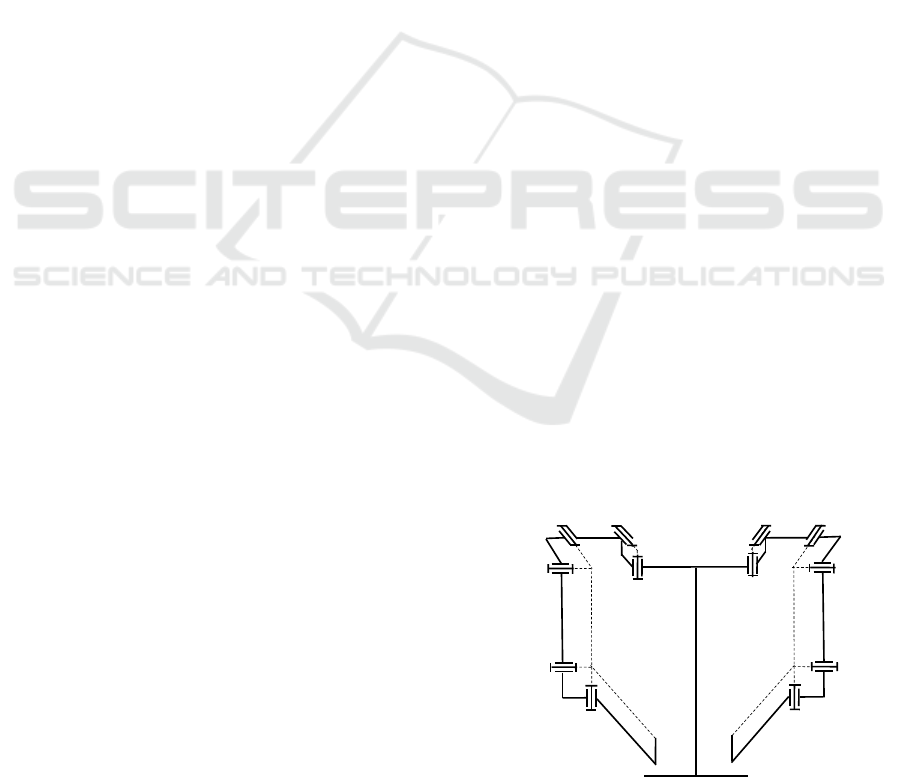
back or ground. An exoskeleton of the upper limbs is
designed in a similar manner as shown in the diagram
of Figure 1 and the photograph of Figure 2. The
mechanical structure of the exoskeleton system
includes two arms R and L, arranged on a fixed base
0, as each arm includes two identical rotating joints
respectively for clavicular motions J1, J2, shoulder
motions J3, J4 and elbow motions J5, J6 (Figure 1).
The arm has a total of 6 degrees of mobility (h = 6),
resembling the natural movement of the human arm
from back to elbow. Structure in Figure 1 is chosen in
order to design an exoskeleton arm, in which modules
with two equal type universal joints are created and
so, unlike other solutions, circular guide and three
axes joints are avoided. Each arm of the exoskeleton
is composed of six movable segments (1, 2, 3, 4, 5
and 6) made mainly of aluminium alloy. The plastic
shells with straps are placed on the segments for
attachment to a human limb (Figure 2). The
generalized masses of the six main segments of the
arm are M
1
= 0.463 kg, M
2
= 0.321 kg, M
3
= 0.497
kg, M
4
= 0.782 kg, M
5
= 0.510 kg and M
6
= 0.793 kg.
The arm and forearm lengths of the exoskeleton
are set with initial lengths L
1
= 0.286 m and L
2
=
0.370 m. Their construction includes lightweight ball
bearings in aluminium housings and built-in position
sensors in their cavity. A high-precision rotary sensor
(BOURNS AMS22B) is used to measure the effective
displacement. The ranges of movements in the joints
J3
J4
J5
J6
EE
4
3
5
6
J2
J1
2
1
0
R
L
J1
J2 J3
J4
J5
J6
1
3
4
5
6
EE
Figure 1: Constructive diagram of a two-handed
exoskeleton.
Evaluation of the Capabilities of a Hybrid Driven Exoskeleton in Passive Mode of Interaction
443
are as follows: J
1
(15°),J
2
(15°),J
3
(120°), J
4
(120 °), J
5
(150 °), J
6
(135 °). They are consistent with the
workspace of the human hand, as shown in (Abane,
2016).
In order to build an actuation that produces a low
impedance while maintaining a high value of the
driving force, the hybrid approach was chosen,
including pneumatic and electric drives operating in
parallel.
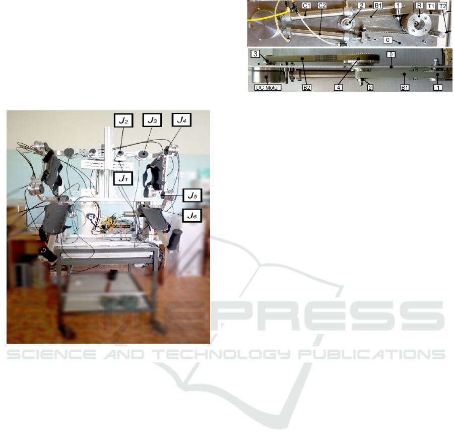
Figure 2: Prototype of a two-handed exoskeleton.
The hybrid actuation of each joint of the
exoskeleton is built as a separate unit located in the
fixed base. A picture of the drive unit of the joint J
4
in
the shoulder is shown in Figure 3. In the base 0 there
is a wheel 1 and mounted thereto reel R with a radius
equal to 31.5mm for winding a cable. Bowden cables
T1, T2 were used to connect the reel R and a similar
reel located in the joint of the exoskeleton.
The electric drive includes a DC electric motor,
on the shaft of which a wheel 3 is mounted (Figure2).
The motor is brushless (MAXON EC 90 flat), with
Ø90 mm, 260 W, 18V, nominal torque Q
m
=1010
mNm, operated with ESCON Module 50/8 HE driver.
To transmit movement from wheel 3 of DC motor
to wheel 1, a backdrivable transmission is used,
including two timing belts B2 and B1 and two wheels
4 and 2 with common shaft. The first gear B2
connects wheels - 3 and 4 and the second gear B1
connects wheels 2 and 1. The first stage of the
transmission have gear ratio n
1
= 3:1 and the second
stage - gear ratio n
2
= 2:1. The overall gear ratio is
n = 6:1.
a)
b)
Figure 3: Hybrid actuation unit for the joint J4 of the
exoskeleton: (a) front view; b) side view.
The pneumatic drive consists of a pair of
pneumatic cylinders, C
1
and C
2
mounted in the base
unit 0, as shown in Figure 3. Pneumatic cylinders
(Aignep) with diameter D = 0.02 m are used. The
cylinders simultaneously drive the opposite sides of
the timing belt B1. Two connected chambers of the
cylinders are supplied in parallel with compressed air
p
a
, and the other two chambers with pressure, p
b
. The
pipes of each pair are connected to two parallel valves
(SMC S070-SDG-32), one of which supplies
compressed air to the chambers and the other releases
the pressure into the atmosphere. Pressure sensors
(Honeywell 40PC100G) are mounted on each
pipeline.
The torque created by both pneumatic cylinders is
r))s(sp-)s(sp(Q
21b21ap
++=
(1)
where p
a
and p
b
are the supply pressures in both
chambers, r is the radius of puley 1 and s
1
and s
2
are
the areas on both sides of the piston.
3 MODEL FOR INTERACTION
FORCE ASSESSMENT
Experiments have been conducted to assess the force
of the interaction in the recovery phase of patients
when they are able to initiate complex independent
movement in a relatively safe and transparent
manner. This is the so-called "patient in charge"
stage, where it is important that the forces of
interaction between the exoskeleton and the patient
are low. If the forces are close to zero it can be said
that the exoskeleton is completely "transparent".
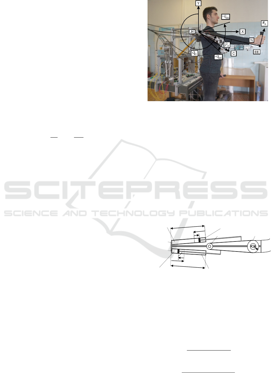
To assess the forces of interaction, dynamic
experiments were performed with movement in one
joint of the exoskeleton, similar to the approach used
in (Bembli, 2019). All joints are locked, and joint J4
is controllable, where flexion - extension in the
shoulder is performed. The operator moves the
exoskeleton arm as shown in Figure 4. The subject of
ICINCO 2021 - 18th International Conference on Informatics in Control, Automation and Robotics
444
the present study are the forces in passive mode,
when they are defined only by the mechanical
impedance of the exoskeleton.
The force of the end effector (EE) applied to the
operator's hand, which overcomes the mechanical
impedance of the exoskeleton and the actuation, is
determined by the inertial, frictional and gravitational
forces, as well as the elastic forces according to the
equation:
N/)QQQQ(F
p
e
gfr
J
h
+++=
(2)
Above N is the value of the radius vector of the EE
where force F
h
is applied to the patient's hand. In
equation (2), the joint torque Q
J
is result of the motor
and the transmissions inertia as well as the
exoskeleton inertia according to equality
)qJq
n
Jq
n
J(Q
e
2
2
tr
2
m
J
++=
ηη
(3)
Here,
J
m
represents the inertia of the motor and
wheel 3, J
tr
represents the inertia of the transmission
wheels 2 and 4,
J
е
represents the inertia of the
exoskeleton and wheel 1. Above n is the overall
transmission gear ratio, n
2
is the gear ratio of second
stage
, η is transmission efficiency, for the case, when
the motor is driven by human (Giberti, 2010).
In equation (2)
Q
fr
represents the friction torque
which is mainly the result of the friction forces
generated in pneumatic actuators and Bowden cables.
The friction force for each side of the parallel drive
can be represented by the following equation
xB)x(signFF
c
fr
+=
(4)
where:
F
c
represents the Columbus friction force, B is
viscous damping coefficient and
ẋ is cable velocity.
These coefficients represent a general estimate of the
various energy effects in pneumatic cylinders,
Bowden cables, DC motors, etc., for which empirical
rather than analytical estimates are known
(Andrighetto, 2006), (Schiele, 2006). The EE friction
torque as a result of the friction forces of the parallel
drive is
rF2Q
fr
fr
=
(5)
where
r is radius of pulley 1.
Figure 4: Harmonic motion imposed by the operator on the
exoskeleton joint J4.
In equation (2), Q
e
g
is the torque resulting from
the exoskeleton gravity according to the equation
)qcossinqg(MQ
e2e1e
e
g
ρρ
+=
(6)
where:
M
e
represents the mass of exoskeleton moving
parts 4, 5, 6; ρ
e
=[ρ
e1
; ρ
e2
]
T
represents the radius vector
of the mass center C in а local frame and g is the
gravity acceleration coefficient.
In equation (2) with
Q
p
is denoted the torque of
the pneumatic drive as a result of the elastic forces
due to air compressibility of the chambers of the both
pneumatic cylinders (C1 and C2), (Figure 5).
L
X
0
x
Chamber -
b
r
T
1
T
2
Chamber - a
L
X
0
x
Chamber - b
Chamber - a
Cilinder – C
2
Cilinder - C
1
1
2
Figure 5: Scheme of the pneumatic drive of the exoskeleton
joints.
Assuming that air is an ideal gas undergoing an
isothermal process, the change in pressure inside each
chamber (a,b) of the two connected cylinders can be
expressed according to (Shen, 2007) as the ratio of the
mass flow rate to the volume of the chamber as
follows
)ss)(xX(
RTm
p
210
(a)
)(a,
+−
=
(7)
)ss)(xXL(
RTm
p
210
(b)
(b)
++−
=
(8)
Evaluation of the Capabilities of a Hybrid Driven Exoskeleton in Passive Mode of Interaction
445

where: m
(a)
, m
(b)
are the mass flow rate entering the
chamber (a, b);
R is the universal gas constant, T is
the gas temperature at the orifice, x is the piston
displacement measured from starting position X
0
for
actuator C
1
and C
2
according to the scheme of Figure
4. In equations (7), (8) the volumes of the connected
chambers are taken into account where
s
1
and s
2
are
the areas on both sides of the piston.
In the conducted experiment it was accepted, that
one chamber of the pneumatic cylinders is supplied
with a pressure
p
a0
and the other p
b0
, after which the
supply and discharge valves of the pneumatic
cylinders are closed. It is assumed that this is done in
the starting position of the cylinders
X
0
, where x = 0.
In this position the pressure inside each chamber (a,b)
of the cylinders can be expressed as follows
)ss)(X(
RTm
p
210
(a)
0
(a)
+
=
(9)
)ss)(XL(
RTm
p
210
(b)
0
(b)
+−
=
(10)
After excluding the general parameters from (9),
(10) to (7), (8), the equations for changing the
pressures in the chambers of the cylinders when
changing their strokes are obtained as follows
)xX(
Xp
p
0
0
0
(a)
(a)
−
=
(11)
)xXL(
)XL(p
p
0
0
0
b
(b)
+−
−
=
(12)
The elastic torque created by both pneumatic
cylinders is determined by (1), where the pressures in
the connected cylinder chambers are represented by
(11), (12). After substituting in (1) it is obtained the
equality of elastic torque as a result of the pistons
deviation x from the starting position
X
0
)rs](s
xX-L
)X-(Lp
-
xX
Xp
[Q
21
0
0
0
b
0
0
0
a
p
+
+−
=
(13)
When the starting position
X
0
of the cylinders
corresponds to the initial position of the arm q
0
,
(Figure: 3) the displacements x of the pistons from the
starting position depend on the deviations
q of the
joint angle from the initial position q
0
as follows
qrX =
(14)
4 EXPERIMENTS AND
SIMULATIONS FOR
EVALUATION OF
INTERACTION FORCE IN
PASSIVE MODE
In this mode, the authors suggest that the patient has
the motor capacity to move his hand independently
and intensively. In passive mode, the electric and
pneumatic drives do not generate active forces. The
operator performs harmonic movements from the
original position with equal amplitude and constant
oscillation frequency. The angle
q in the joint J4
determines the position of the arm, assuming that q =
0
when the arm coincides with the Y axis (Figure 4).
To measure the interaction force, a load cell is located
on the end effector, where the force is applied to the
operator's hand.
4.1 Passive Mode of Interaction
without Pressure in the Chambers
A. Experiments. In this experiment, a passive mode
is realized, as the valves of the pneumatic actuator are
open to the atmosphere (
p
a
= 0 and p
b
= 0) and no
voltage is applied to the electric actuator. The human
operator has performed harmonic movements from
the initial position
q
0
= 260
0
at an amplitude of about
q
m
= 20
0
with an oscillation frequency of about ω =
2.1 rad/s. The forces applied by the hand of operator
to overcome the mechanical impedance of the
exoskeleton changes as shown in Figure 6 a). As can
be seen from the experiment, the interaction force has
an average value of -8.2 N determined mainly by the
weight of the exoskeleton. Dynamic deviations
around it are about ±2 N.
B. Simulations. To assess the parameters of the
actuators and to evaluate the correctness of the
constructed mathematical model, dynamic
simulations of the movements in joint J4 are
conducted. To model the harmonic motions from the
initial position
q
0
with amplitude q
m
and oscillation
frequency ω, the following law of motion is used
0m
q)tsin(qq +=
ω
(15)
as well as the laws of velocity and acceleration
obtained after differentiation of (15) as presented in
(Chakarov, 2020).
ICINCO 2021 - 18th International Conference on Informatics in Control, Automation and Robotics
446
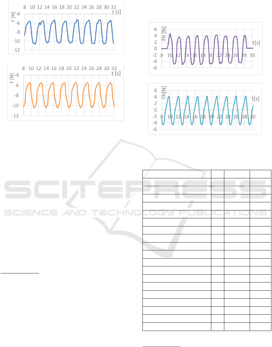
a)
b)
Figure 6: Interaction force in passive mode without pressure
in the chambers: a) experiment; b) simulation.
The simulations were conducted with the same
values of the kinematic parameters used in the
previous experiment: starting angle
q
0
= 260°,
amplitude q
m
= 20° and frequency of ω = 2.1 rad/s.
The forces applied by the hand of human operator
to overcome the mechanical impedance of the
exoskeleton are calculated according to equation (2).
The graph in Figure 6 b) shows the change in the
interaction force (2) as result of the inertia torque (3),
the friction torque (5) as well as the exoskeleton
gravity (6). The values of the mechanical parameters
using for calculations with equations (3) – (6) are
shown in Table 1.
4.2 Passive Mode of Interaction with
Gravity Compensation
A. Experiments. In this experiment, the exoskeleton
arm is gravitationally compensated in the initial
position
q
0
. For this purpose, one chamber of the
pneumatic cylinders is supplied with a pressure equal
to
p
a
= 250 kPa and the other - p
b
= 0, after which the
supply and discharge valves of the pneumatic
cylinders are closed. In this case, the passive forces
applied by the operator hand are result not only of the
sources mentioned in the previous experiment but
also of the forces
Q
p
resulting from the
compressibility of the air in the cylinder chambers.
The operator has performed harmonic movements,
from the initial position
q
0
= 260
0
, with amplitude of
about
q
m
= 23
0
and frequency of about ω = 2.7 rad/s.
The change in interaction force is shown in Figure 7
a). The experiment shows a force change in both
directions about ±4.5 N.
a)
b)
Figure 7: Interaction force in passive mode with gravity
compensation: a) experiment; b) simulation.
Table 1: Electric and pneumatic drives parameters.
Parameter name Value
Motor efficiency η
m
90 %
Motor inertia J
m
508.10
-6
kgm
2
First stage reduction n
1
3 : 1
Second stage reduction n
2
2 : 1
Transmission efficiency η
tr
97 %
Transmission inertia J
tr
173 10
-6
kgm
2
Piston area side 1 s
1
314 10
-6
m
2
Piston area side 2 s
2
264 10
-6
m
2
Pneumatic cylinder diameter D 0.020 m
Pneumatic cylinder stroke L 0.125 m
Piston starting position X
0
0.050 m
Actuation viscous friction B 665 Ns/m
Actuation Coulomb friction F
c
8.61 N
Exoskeleton mass M
e
2.085 kg
Exoskeleton inertia J
e
0.198 kgm
2
Radius of EE N 0.660 m
Radius of pulley 1 r 0.0315 m
Coordinate 1 of mass center ρ
e1
0.256 m
Coordinate 2 of mass center ρ
e2
0.031 m
B. Simulations. In the conducted simulation, the
interaction force includes all components according
to equation (2). The torque of the pneumatic drive
(13) is calculated in the initial position
q
0
with
pressures of the two chambers, respectively p
a
= 250
Evaluation of the Capabilities of a Hybrid Driven Exoskeleton in Passive Mode of Interaction
447

kPa and p
b
= 0. The same harmonious movement as
in the previous experience is simulated with the
kinematic parameters: starting position
q
0
= 260°,
amplitude q
m
= 23° and frequency of ω = 2,7 rad/s.
Figure 7 b) shows the force of interaction which is the
result of the sum of dynamic forces, gravity forces
and elastic forces in the chambers of the pneumatic
cylinders. The elastic force acts as an elastic balancer
of the gravity load. The interaction force is 0 at the
initial position and fluctuates ± 4.5 N around this
value, as in the previous experiment.
5 CONCLUSIONS
The paper reveals the mechanical design of an
exoskeleton of the upper limbs, which uses the
scheme of hybrid drive with electric and pneumatic
actuation, thus producing a lower impedance due to
pneumatics, while maintaining high driving force and
rapid force response due to electric actuation. Further
reduction of the mechanical impedance is achieved by
placing the components of the hybrid drive in the
fixed base.
Several experiments with the available
mechanical prototype of the exoskeleton were
performed in the work to test the hypothesis that the
proposed hybrid drive is able to provide the two
modes of interaction: a) “robot in charge” mode,
when the exoskeleton applies forces with high
impedance and b) “patient in charge” mode when the
forces of interaction with the operator are low due to
the reduced impedance of the robot.
In the experiments, the force between the operator
and the exoskeleton was evaluated. The force of
interaction was obtained from passive forces, which
are the result of inertia, friction and gravity, as well
as the elasticity of pneumatics. In “patient in charge”
way the patient-initiated harmonic motion was
studied in two cases - without pressure in the
chambers and with pressure for gravity
compensation.
In the first case, the force of interaction
determined mainly by the exoskeleton gravity
indicates that the exoskeleton arm is relatively heavy
(
F
h
=-8.2 N). As a result of added inertia and friction
forces from harmonic movements, this force
oscillates from -5.8 to -10.2 N. When gravity is
compensated passively by pressure in the chambers
of pneumatic cylinders, the force of interaction is
determined by the elastic forces of compressed air, as
well as by the inertia forces and friction. For the
selected harmonic deviations, the force of interaction
reaches relatively high values (
Fh = ± 4.5 N).
The work also includes several computer
experiments to assess the parameters of the actuators
and the correctness of the constructed mathematical
model. Computer experiments show a similar change
in the interaction force as in the real experiment. It
can be noted that the parameters introduced in the
model such as exoskeleton mass and coefficients of
Coulomb and viscous friction in the actuators (Table
1) have quite high values.
The conducted experiments show that the
resulting forces of interaction in passive mode are
essential in terms of transparency, but are not a threat
of security. In active mode of operation, the forces of
interaction can be reduced by active compensations,
but the created low values of the forces in passive
mode are a guarantee of general security.
The design and control of this exoskeleton are
under development. Future work will be done by
incorporating the controller and assessing the
transparency and safety of the interaction between the
patient and the exoskeleton in active mode.
ACKNOWLEDGEMENTS
This research was supported by the Operational
Program "Science and education for smart growth"
through the project “MIRACle”, № BG05M2OP001-
1.002-0011, to which the authors would like to
express their deepest gratitude.
REFERENCES
Manna S. K., Dubey V. N., 2018. Comparative study of
actuation systems for portable upper limb exoskeletons,
Medical Engineering and Physics, 60, 1–13.
Jarrasse, N., T. Proietti, et al., 2014. Robotic Exoskeletons:
A Perspective for the Rehabilitation of Arm
Coordination in Stroke Patients, Frontiers in Human
Neuroscience, Vol.8, Art.947, 1-13.
Veneman, J.F., R. Ekkelenkamp, et al., 2006. A series
elastic- and bowden-cable-based actuation for use as
torque actuator in exoskeleton-type robots, The Int.
Journ. of Rob. Research, vol. 25(3), 261-281.
Hogan N., 1985. Impedance Control: An Approach to
Manipulation, ASME J. Dynamic Systems Meas. &
Control, 107: 1-24.
Ansarieshlaghi, F. and P. Eberhard, 2019. Hybrid
Force/Position Control of a Very Flexible Parallel
Robot Manipulator in Contact with an Environment. In
Proc. of the 16th International Conference on
Informatics in Control, Automation and Robotics
(ICINCO 2019), Vol.2, 59-67.
ICINCO 2021 - 18th International Conference on Informatics in Control, Automation and Robotics
448

Morales R., et al., 2011. Pneumatic robotic systems for
upper limb rehabilitation, Med. Biol. Eng. Comput. 49,
1145–1156.
Rouzbeh B., et al.,2019. Design, Implementation and
Control of an Improved Hybrid Pneumatic-Electric
Actuator for Robot Arms, IЕЕЕ Access, Vol. 7, 14699
– 14713.
Nakata Y., T. Noda, J. Morimoto, and H. Ishiguro, 2015.
Development of a pneumatic-electromagnetic hybrid
linear actuator with an integrated structure, Proc.
IEEE/RSJ Int. Conf. Intell. Robots Syst., Sep./Oct.
2015, 6238–6243.
Chakarov D., Veneva I., Tsveov M., Mitrouchev P., Venev
P., 2019. Design of a Two Arms Exoskeleton as Haptic
Device for Virtual Reality Applications, Lecture Notes
in Mech. Eng., Springer Nature, Chapter 25, 252-262.
Abane, A., Guiatni, et al., 2016. Mechatronics Design,
Modeling and Preliminary Control of a 5 DOF Upper
Limb Active Exoskeleton, Proc. of the 13th Int. Conf.
on Informatics in Control, Automation and Robotics
(ICINCO 2016), Vol. 2, 398-405
Bembli, S., Haddad, N. and Belghith, S., 2019. A Terminal
Sliding Mode Control using EMG Signal: Application
to an Exoskeleton- Upper Limb System. Proc. of the 16
th Int. Conf. on Informatics in Control, Automation and
Robotics (ICINCO 2019), Vol.2, 559-565.
Giberti H, Cinquemani S, and Legnani G., 2010. Effects of
transmission mechanical characteristics on the choice
of a motor-reducer. Mechatronics; 20(5), 604–610.
Andrighetto P., Valdiero A., Carlotto L., 2006. Study of the
friction behavior in industrial pneumatic actuators.
ABCM Symposium Series in Mechatronics, Vol. 2, 369-
376.
Schiele A., Letier P. et al., 2006. Bowden cable actuator
for force-feedback exoskeletons. IEEE Int. Conf. on
Intelligent Robots and Systems: 3599-3604.
Shen X. and M. Goldfarb, 2007. Simultaneous force and
stiffness control of a pneumatic actuator, Journal of
Dynamic Systems Measurement and Control, vol. 129,
no. 4, 425–434.
Chakarov D, Iv. Veneva, M. Tsveov, P. Venev, 2020. Study
of a Hybrid Actuated Exoskeleton for Upper Limb
Rehabilitation, Proc. of the 17th International
Conference on Informatics in Control, Automation and
Robotics, ICINCO 2020, Vol. 1, 498-505.
Evaluation of the Capabilities of a Hybrid Driven Exoskeleton in Passive Mode of Interaction
449
