
Detection and Tracking Techniques for Infrared Searching and
Tracking System with Robust Control System
Vijay Kumar and S. P. Gangwar
Department of Electronics Engineering
Kamala Nehru Institute of Technology, Sultanpur-228118 (U.P.) India
Keywords: Infrared (IR), IRST, LRF, Photo Sensitive Device (PSD), JAPD.
Abstract: Infrared searching and tracking system is the heart of modern armament system generally used in air
defense and missile shields system. The IRSTs used in fighter aircraft, tanks and missile defense systems to
passively search, detect, track, classify, and decides their priorities in multiple airborne targets under all
aspects and engage the target from long ranges as possible. In this paper, authors have proposed a new
concept in which all three units i.e. IR channel, TV camera, and LRF are installed in a single optical
window. Also, studies have been done on various detection and tracking algorithms for multiple airborne
targets in clusters, clouds and noisy environmental conditions and authors have find out a suitable algorithm
and control system for IRST system.
1 INTRODUCTION
With the development of modern electronic warfare
system, infrared searching, tracking and ranging
system is used to detect and track possible threats
through IR signature but it is less efficient in
traditional microwave frequency radar system. For
ranging, it uses a coherent high power laser beam to
measure distance of target. Due to capability of
passive detection and tracking of target, the IRSTs
(Yilmaz, 2003) are getting more importance in air
defense and missile defense. Infrared detection and
tracking system has significant advantage over
radars such as passive surveillance, which do not
suffer jamming by jammer and gives warning
against anti-radiation missiles threats.
The IRST system surveys environment and
analyses the IR radiation, emitted by target as
compared to background (Nengli, 2001) (Yang,
2001). Generally, western IRST systems IR channel
and TV camera is installed at same optical window/
platform, and LRF installed other optical platform.
On the other hand in Russian system IR channel and
laser range finder (LRF) worked in same optical
window. The proposed IRST system have all three
units IR channel, TV camera, and LRF is installed in
a single optical window with two different signal
processer, first IR signal processor use for IR signal
processing in IR channel and second video signal
processor for video signal in Thermal/ video
channel. For IR channel authors have used mid IR
having wavelength 3.5 to 5.5 µm for beyond visible
range target and for thermal channel, authors have
used upper IR having wavelength 10 to12.6µm for
visible range target.
To achieve IRST task to detect and track target
various different algorithm may be used. The
Interacting Multiple Models (IMM) filters algorithm
(Blom, 1998) (Mazor, 1998) is best for data
selection and processing in IRST application. This
algorithm uses multiple Interactive models for
parallel processing.
The GNN and JPDA (Konstantin, 2003)
(Tchango, 2003) tracks targets 5 to 6 times faster
than MHT depending on the motion of targets by
using various models. However, The IMM motion
model makes all three trackers run 3 to 4 times
slower. Tracker JPDA with IMM filter and Tracker
TOMHT (Blackman, 2004) with IMM filter track-
maneuvering targets more precisely and did not
break or lose track even during turns and in the
ambiguous region. However, runtime for a tracker
TOMHT is significantly longer than using tracker
JPDA and computational data is less hence requires
less memory space than tracker JPDA. In case JPDA
with Interactive Multiple model algorithm (IMM)
202
Kumar, V. and Gangwar, S.
Detection and Tracking Techniques for Infrared Searching and Tracking System with Robust Control System.
DOI: 10.5220/0010567000003161
In Proceedings of the 3rd International Conference on Advanced Computing and Software Engineering (ICACSE 2021), pages 202-211
ISBN: 978-989-758-544-9
Copyright
c
2022 by SCITEPRESS – Science and Technology Publications, Lda. All rights reserved

proves to be best for real time application and best
option for IRST system.
In this paper, authors have proposed a robust
control system for the composite axis (azimuth and
elevation both) in IRST System to solve jitter and
oscillation problem at airborne vibration
environment. Robust control system is used to
improve the control performance. A servo-control
motor with Tunable PID controller (Li, 2017) used
for control the scanning mirror in azimuth and
elevation. For focusing problem of IR/ thermal
signal on PSD device, solved by Roll control drive
and optical modulator. The roll control drive aligns
the optical line sight between scanning mechanism
and PDS through servo control motor and tunable
PID controller in azimuth. Optical modulator aligns
the fine mismatch the position at elevation between
scanning mechanism and PSD.
2 BASIC PRINCIPLE OF IRST
SYSTEM
The principle of IRST system can be divided three
parts:
i. System ensures reception of IR (infrared)
signals from airborne as well as ground & water
surface target. Searching is detection and auto-
tracking of target through its heat radiation with
measurement of angular coordinates of the targets,
when target is beyond visible range (BRV)
(Srivastava, 2007).
ii. System ensures reception video signals targets
through its video signal with measurement of
angular coordinates of the targets, when target is
visible range.TV camera is used for video signal
recording and processing.
iii. System ensures transmission and reception
LASER beam reflected from targets by LASER
Range Finder (LRF) and calculate the range of target.
2.1 Detection Principle
Any object, whether solid, liquid or gas whose
temperature is above absolute zero (-273°C or 0° K)
would emit electromagnetic radiation called IR
signature. When the object is in thermal equilibrium
with its surrounds then it is simultaneously radiates
and absorbs a constant band infrared radiation at
same rate.
The IR detector of IRST system detects the target
based upon its infrared radiation. IR emission by a
target in rear hemisphere is more than that in front
hemisphere. The energy of heat emission expressed
by Boltzmann law:
4
)( TEEnergy
(1)
𝛿 = Boltzmann constant (1.38X10
-23
m
2
Kg s
2
K
-1
)
T= absolute temperature of the body.
This heat gives rise to radiation of IR waves. Wien’s
displacement law gives the relation between IR
wavelength and absolute temperature expressed as:
T
m
Wavelenght /2897)(
(2)
ʎ
m
= maximum wavelength of IR Radiation.
According to reference (Srivastava, 2007)
IRST system detects targets from long distance that
located at beyond visible range and appears on
detector plane as point image. The maximum
detection range defined by using range formula for
point image target:
SnNei
R
tEDrRange */*()(
( (3)
t
R
= Atmospheric transmittance over the sight line of
target
∆E= IR radiation intensity of target,
Sn= Signal-to-noise ratio
Nei= Equivalent noise irradiance of the sensor.
The position sensitive detector is an optical
transducer use to find position of falling light on its
surface. Generally, Photosensitive Detectors devices
divided in two categories:
a) Thermal Photo Sensitive Detectors
b) Quantum Photo Sensitive Detectors.
Thermal Photo Sensitive Detectors are
detectors that sense the infrared Signature and
convert IR flow into electrical signal depending on
intensity of IR flow without any requirement of
cooling system. These detectors are also very
sensitive to surrounding temperature but responses
are slow. The same principal used by Quantum
Photo Sensitive Detectors but these detectors
(Koretsky, 2013) are requiring cooling to distinguish
the IR signature of target from electrical noise of
detectors material. The detectors device packed in
vacuum chamber or cold shield. Cold shield consist
of detector, optical window and cooling hose and
prevents thermal energy surround.
2.2 Detection through TV Camera
Although in this era, the comparison between the
color and monochrome camera is illogical but most
important points to be considered while choosing a
Detection and Tracking Techniques for Infrared Searching and Tracking System with Robust Control System
203
thermal camera for detection and tracking of targets
in IRST. In the IRST, resolution is important but
color is not necessary then Monochrome cameras are
better for Long-range application and color CCD
camera for medium range application. TV camera
has two parts:
a) CCD Sensor.
b) Optical system with zoom control gear.
2.2.1 CCD Sensor Sizes / Camera Resolution
Sensors (CCD/CMOS) often referred to fraction of
an inch designation such as ¼” or 4/3” called optical
format. Aspect ratio of most of the CCD devices is
4:3. For selection of camera resolution and lens focal
length, the number of column and rows of CCD
pixels in the camera sensor are important. It further
depends on the following factors.
i. Field of view is the Area under surveillance
that is cover by camera.
ii. Size of the target, that camera has to detect.
iii. Distance: from camera to target.
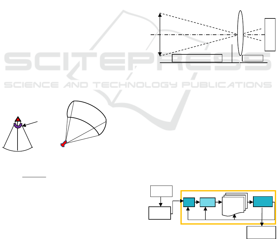
Viewing filed of all pixels of one Horizontal line
in camera sensor will be distributed throughout the
length of the arc as shown in fig. Spacing between
two nearby pixels in the arc distribution is equal to
Length of arc/number of pixel in one horizontal line.
To detect the air target by TV camera means the
spacing between two pixels should be equal or
slightly less than the width of aircraft. If it is greater
than the aircraft width
Camera sensor
Viewing angle H
V
D=30D=30
A D=30 C
B
Figure.1: viewing angle and viewing area of camera sensor
S
spacing =
14
36.8199
Dection
H
.
So H
detection
≥ 8199.36/14 ≈ 586 (4)
Then aircraft will not be detected. Means number of
pixels in Horizontal line must be equal or greater to
586.As per Johnson criteria, at least two pixels are
required for detection with 50% probability means
total no of pixels are required is:
586×2=1172 pixels (5)
The
same calculation can do for Elevation. Further
for aspect ratio 4:3. Therefore, size of camera sensor
for recognition is must be equal to or greater than
1758×1318 nearby standard size of CMOS Sensor is
2448×2048= 5 Mega pixel. SONY IMX250 series
will be suitable for this application.
2.2.2 Optical System with Zoom Control
Gear
Above camera sensor cannot work alone without
optical system. Optical system with zoom control
will focus the complete FOV on the sensor because
FOV is 5.87 X 5.87 in degree or 8199 X 8199 in
meter and sensor’s pixel size is 3.45 X 3.45 µm
(SONY IMX5XX SDI).For calculation of optical
zoom parameters for Thermal camera, Focal Length
calculated as per figure 2. For Recognition as per
Johnson criteria 6 pixel is required so effective pixel
size is:
= 3.45×6= 20.7 µm (6)
Figure 2: Focal Length calculations
Focal Length recognition BC = Focal Length BC
= (AB× Pixel size)/ Target size
=(30000×20.7×10-6)/14 = 1109 mm (7)
As per above calculation focal length is required
from 39.4 - 1109 mm The standard nearby focal
length available is 25 -1550mm with 62× zoom.
2.3 Tracking Principle
Tracking is the prediction of future locations of
moving target, based on its estimation and
measurements by uses deferent models of real
environment that estimate present, past and even
predict future states.
Figure 3: Block diagram of the system
A
F
O
V
B
C
Sensor
Working distance
Focal length
Sensor
Detection
Presentation
Gatin
g
Associati
on
Track/
h
yp
othesis
Association
strategies for
tracking
ICACSE 2021 - International Conference on Advanced Computing and Software Engineering
204
The track is a symbolic representation of a target
moving in given vision of filed. In tracking system, a
track is representing by a filter state gets update on
each new measurement. Tracking function can
divided into following two steps:
i. Estimate the current state of target based on
tentative measurements selected according to
certain rules (Gaitanakis, 2019).
ii. Calculate the accuracy and credibility associated
with state estimation.
On the basic of hypothesis the tracker are divide in
two categories:
1. Single hypothesis tracker,
2. Multiple hypothesis tracker
2.4 Range Measuring Principle
LASER used in the form of a pulsed signal for
finding out the range of the target. Time taken by a
LASER beam to travel to and fro is compute to
measure the range as per following relationship:
2
* tC
R
LRF
(8)
d = range of the target,
C = velocity of light.
t = time taken to travel to and fro,
Depending on the beam divergence, the size of
target and laser spot projected on a target the targets
are can be divide in two categories as under filled
targets and overfilled targets. In under filled target,
all of energy in laser pulse is scattered by the target.
In the over filled target, only a segment of pulse
energy will be scattered by target surface at angle of
incidence ϴ. According to (Williams, 2018) the
maximum effective range R
max
of LRF is calculated
given by equations:
When target is under-filled, (i.e. target is larger than
laser spot)
phf
t
UF
ENEIN
DcasP
WR
*4
)(
1
max
2
0
(9)
When target is over-filled, (i.e. target is smaller than
laser spot)
phf
tt
UF
ENEIN
DcasAP
WR
*4
)(
2
2
max
2
22
4
0
(10)
W
0
= Lambert function. This special function is
compute numerically by mathematical software
where it known as Lambert w.
NEI = noise equivalent input,
At = target area
Eph = photon energy in joules,
η= efficiency of optical system,
Pt= transmitted pulse energy,
D =is receive- aperture diameter,
N
f=
factor required to achieve particular FAR
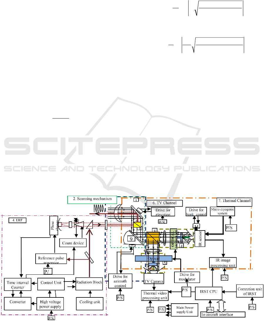
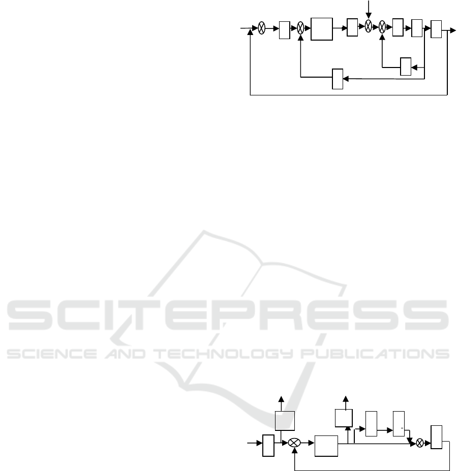
3 THE FUNCTIONAL DIAGRAM
AND DESCRIPTION OF IRST
The schematic functional diagram of IRST given in
following figure 4 and functional details given
bellow:
Figure 4: Schematic functional diagram of IRST system
Detection and Tracking Techniques for Infrared Searching and Tracking System with Robust Control System
205
Optical system of infrared channel, which
ensures reception and focusing of infrared emission
in plane of installed infrared receiver. It consists of
fairing (1), scanning mirror (2), and fixed mirror (9),
mirror-lens objective with modulator (4).Optical
system of thermal channel, which ensures reception
and focusing of thermal IR emission in the plane of
installed thermal receiver. It consists of fairing (1),
scanning mirror (2), fixed mirror (9), wave from
splitter (8), mirror-lens objective (5) with modulator,
which is a plain-parallel mirror.
Moving scanning mirror is set up the scanning field
/zone and controlled by motor and digital position
sensors of scanning mirror in azimuth and angle of
Elevation. Turning of PSD by an angle proportional
to angle of scanning mirror in azimuth Carried out
with the help of roll drive, for compensation of
turning of image in focal plane of optical system.
Roll pitch motor control unit, which control IRST
Roll drive using the information from bank and
azimuth angle sensors for turning PSD-1 and
modulator. Diaphragm pitch motor control unit, that
carries out diaphragm drive control for regulating
infrared stream at input of objective lens. During
this, information from image amplifier about target
signal amplitude is used.
Logical block which generates the impulses
ND1 and ND2 during zero position of modulator.
In Thermal camera during video recording
some time require to zoom the particular area of
view there are two type of zoom system first optical
zoom can be obtained by optical zoom lens and
second digital zoom can be obtained by image
processing tools. To control the thermal IR intensity
authors have used gain control unit, which control
the gain of camera according to amplitude of
detected signal by controlling the diaphragm
aperture.
Optical system of laser ranger consists of
airing, laser optics mounted at scanning mirror, fixed
mirror, waveform splitter mirror in laze path. Optical
circuit of laser ranger ensures generation of laser
beam in the reflected direction of line of sighting,
reception and focusing of radiation from the target in
plane of mounting of photoreceptor (PSD-2) of laser
ranger.PSD-2, which converts reflected energy from
target or from the surface of the ground into
electrical signal. Pulse generator, generates reference
pulse of time interval counter and echo-pulse. Time
interval counter which measures delay time between
the reference impulse and first arrived echo impulse
in probing clock.
3.1 Working Mode of IRST
IRST system has generally three modes. One
detection and tracking mode called infrared mode
(IR channel), distance-measuring mode called laser
mode (LR mode) and target detection and tracking
through video channel (TV Camera).
1. Mode 0: IR and TV mode;
2. Mode 1: IR mode;
3. Mode 2: TV mode
3.2 Viewing/Scanning Mode Operation
In IR mode, following article has four operational
modes, which listed below.
i. Large field Surveillance Mode
ii. Small field surveillance Mode.
iii. Lock On & Tracking.
iv. Working of Laser range finder (LRF)
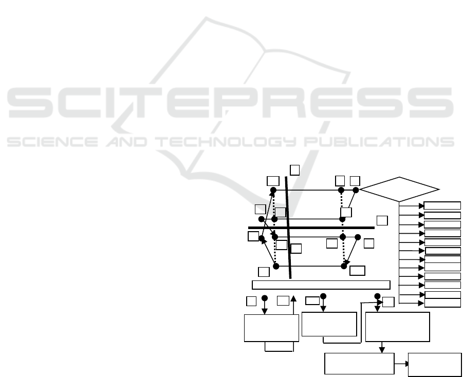
3.2.1 Large Field Surveillance Mode
Block diagram of big surveillance field mode shown
in figure 5. This mode solved by ICPU with
frequency 500 Hz. At this, dedicated software
program is use to establish coordinate of boundary
of the field (70
0
X 20
0
) in preset order. At the points,
12, 3, 6, 9 the sign of control signal for drive is
changed. At the points 3, 6, 9, 12; operation carried
out on E. The coordinates of each new point of
trajectory of sighting line given in the form of target
Figure 5: Flow diagram of big surveillance field (70
0
X
20
0
) mode
3
E
12
Y1
Y2
Y3
Y4
Supply of
End of Frame
Establishment of
Field boundaries
Processing of target
designation
Working on TsU
Shaping of
Surveillance field
and su
pp
l
y
out
p
ut
Supply of
Start of Frame
Sha
p
e of scannin
g
field (70
0
X 20
0
)
Analysis of Stage
Y1 Sta
g
e 0
Y2 Sta
g
e 1
Y4 Sta
g
e 2
Y4 Sta
g
e 3
Y3 Sta
g
e 4
Y4 Sta
g
e 5
Y4 Sta
g
e 6
Y3 Stage 7
Y4 Sta
g
e 8
Y3 Sta
g
e 9
Y3Stage10
Y3Stage 11
1 2
10
4
9
5
6
7
8
11
A
O
ICACSE 2021 - International Conference on Advanced Computing and Software Engineering
206
indication on A and H. When operating in 140
0
X
20
0
modes, the point with coordinates of external
target indication is center of field. The whole field
has 12 checkpoints. Points 1, 4, 7, 10 are specific in
that, they are starting of working sections, on which
calculation and supplying of coordinate of detected
targets onazimuth φy andelevation angle φz:
φy = φ
HDF
y= φAt,
φz = φ
HDF
z= 2φEt ±δE; is carried out. (11)
δE – mismatching code between coordinate line of
sight and coordinate target on angle of elevation.
When switch on first time, for smooth movement of
line of sight, the current value of output code of
azimuth sensor φAt and doubled current value of
output code of elevation angle of sensor 2φEt sent
tocorresponding memory cell, where the value of
integrator is solved:
φAii = φAt, &φEii = 2φEt. (12)
After working out checkpoint 11, the signal “End of
frame” (“EF”) is supply to onboard digital computer.
Marking of view field (140
0
x 20
0
) is carryout with
respect to the coordinate of external target indication
φ
TD
y, φ
TD
z (on A & E) in accordance with the stage
number.
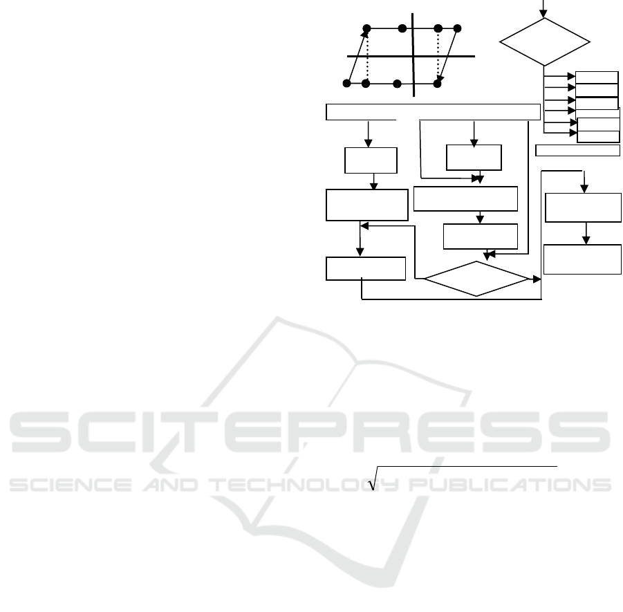
3.2.2 Small Field Surveillance Mode
Block diagram of Small surveillance field mode
given in figure 6. This mode solved by ICPU with
frequency equal to 500 Hz. The following tasks
solved:
i. Viewing the field (30° X 10°); ii. Drive
control on bank.
iii. Tracking the target in the field (30° X 10°);
(13)
The whole field (30° X 10°); has six
characteristic points. Until detecting first target, the
coordinates of external target indication are center of
field. On detection of target, device is shifted to
internal target indication the coordinates of tracking
target to be tracked are its coordinate. At this, the
task of selecting tracking target arises, coordinates of
which determine the position of center of viewing
field in the next frame. In the remaining, the shaping
of viewing field carried out similarly as in (140° X
20°) mode. During first setting of device to mode, if
still it is not in any mode, for smooth movement of
sighting line, the current value of output code of
azimuth sensor φAt and doubled value of output
code of elevation angle sensor 2φEt are recorded in
corresponding memory cell, where the values of
integrator:
φAii = φAt; ΦEii = 2 φEt, are served. (14)
Figure 6: Flow diagram of small surveillance field (30
0
X10
0
) mode
ΦEii –Current value of angle of elevation integrator;
ΦAt&ΦEt – Current values of Azimuth& elevation
sensor; For determining the coordinate of target,
near to the center (for frame), calculation of distance
between the coordinates of target and coordinates of
center of field carried out by formula:
(15)
Minimum distance from the center of field is
established.
3.3 Lock on & Tracking Mode
Firstly, lock on is effected in 4
0
azimuth and4
0
elevation area. Here IRST mirror does not move in
elevation at all. There are 64 photo elements
arranged vertically, which covers 4
0
in elevation. To
cover 4
0
in azimuth, a small mirror inside the Opto-
mechanical assembly oscillated at the rate of 25 Hz
since it is very difficult to move the outer IRST
mirror with such a high rate due to its bulkiness. The
target automatically brought to the center of the area
with the help of control signal from the ICPU to the
outer mirror antenna. As soon as the target brought
to the center of (4
0
X 4
0
) area, the second phase of
lock on starts. In this phase of lock-on, the coverage
area is reduced to 40’ X 40’. Elevation coverage of
the area done with the help of 12 central photo
receivers, without physical movement of the
antenna. In azimuth plane, 40’ covered by
oscillation of the inner small mirror at the rate of
22
HDF
z
HDF
y
zy
No
Supply of
START frame
Supply of
Frame transfer pulse
φ
HDF
Azi +∆=φ
HDF
Az
φ
HDF
Aei+∆= φ
HDF
Ae
3
2
1
A
E
(a) Shaping of Small surveillance field (30
0
X10
0
)
A
z
4
6 5
15
0
-15
0
Check for beyond
field limit boundaries
φ
A
z
HDF
and
φ
A
E
HDF
Target Designation
follow -up
< Working on TsU>
Target designation
rection for target
Y2
Y1
Y3
Y4
Supply of
END Frame
Calculation and Supply
Frame transfer pulse
Find Location of target
close to the center
Yes
Y4 Sta
g
e3
Y4 Sta
g
e
2
(b) Stage analysis
Y4 Stage5
Y3 Stage4
Y2 Stage1
Y1 Stage0
Analysis
of Stage
Detection and Tracking Techniques for Infrared Searching and Tracking System with Robust Control System
207
100 Hz. As soon as the target brought to the center
of 40’ X 40’ area, the third phase of lock on starts.
Now, the lock-on area further reduced to 12’
azimuth and 18’ elevation. Azimuth plane is
covered by oscillating the inner mirror at 100 Hz,
whereas elevation plane covered by 06 central photo
receivers (out of previous 12).
3.4 Working of Laser Range Finder
(LRF)
LRF operates in two modes as follows: Modes of
operation of LRF decided by a command received
from Mission Computer through electronic unit.LRF
Operates in stand- by mode when the target range is
above than 1600 meters. Laser pulse, repetition
frequency is 0.25Hz. Range up to the target
calculated by timer circuit by calculating the period
of pulse and generated equivalent range of target.
LRF Operates in main mode when the target range is
less than 1600 meters. Laser pulse, repetition
frequency is 2Hz Range up to the target is calculated
and generated as stand-by mode.
4 ROBUST COMPOSITE AXIS
CONTROLSYSTEM FOR IRST
The tracking precision, accuracy and stability are
most important in IRST system. Scanning
mechanism has mismatching position error between
servo-control system and sensor unit at azimuth or
elevation arrived, then scanning mechanism
oscillating at their current position. This problem
comes due to mismatching in sensor reading servo
control feedback or motor eddy current and
hysteresis loss of motor and this effect called jitter.
To overcome limitation of IRST control system we
proposed a control system for both axis azimuth and
roll is called composite axis controller consists of the
scanning mirror angle sensor, stepper motor for
drive and free steering movable control
system(FSM) with modulator. The robust controller
consists of PI controller with following coefficients
given as:
J = Armature moment of inertia
T
F
= Armature viscous damping,
.K
e
= Velocity constant.
Figure 7: Control system
4.1 Free Steering Movable (FMS)
Controller to Compensate Image
Turing Due to Roll of Target
For focusing problem of IR / thermal, signal on
PSD during the turning of image due to rolling of
target solved by free steering movable robust
controller. The block diagram FMS controller
shown in figure 8 and consists of:
1. Roll/bank control drive
2. Optical modulator
The roll control drive aligns the optical line
sight between scanning mirror and PDSin azimuth
through servo control motor and tunable PID
controller in azimuth and Optical modulator aligns
fine mismatch position between scanning mirror and
PSD in elevation. The optical modulator is
oscillating mirror fixed on two springs. Its oscillate
at 2Hz in 4
0
X 4
0
viewing flied and .25Hz in40’ X40’
viewing flied during lock-on and tracking mode. At
frequency 25 Hz, Zero position fixation error is 2’.
Figure 8: FMS Controller
At frequency 100Hz is 0.2’. The signals N
D1
and N
D2
are standard digital signal logic 1with duration 2 to
20 µ sec.
5 RESULT AND DISSCUSSION
To find the best algorithm for IRST detection and
tracking for maneuvering targets, authors have
estimated the motion of targets by using various
∆
U
W
u
G
K
B
ϴ
N
D1
N
D1
K
BS
N
D2
N
D2
2
ϴ
u
T
f
K
e
K
1/LS=
R
i
ϴ
K1 1/J
1/S
1/S
T
ICACSE 2021 - International Conference on Advanced Computing and Software Engineering
208
models. It assumed that two targets are closely
spaced; they can fall within a single sensor
resolution cell and sensors reports, only single
detection form multiple targets when targets are so
closely spaced that sensors cannot resolve them
spatially.
To demonstrate a case where sensor reports an
ambiguously assigned to tracks, authors have created
a simple scenario. In this scenario, a single IRST
radar sensor object, located at origin, scans a small
region about 20 km from radar. Initially, radar
reports about two detections per scan. When
detections are coming from a region around X = 0, Y
= -20 km position, the radar reports a single
detection per scan for a while, followed by two radar
detections reported from around Y = -19.5km and
toward the sensor (up).
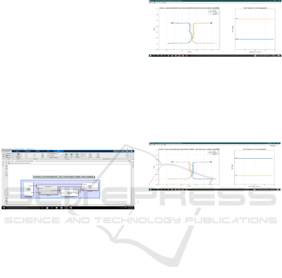
Simulink model for evaluation of detection and
tracking algorithm for closely spaced target shown
in figure 9.
Figure 9: Simulink model for evaluation of detection and
tracking algorithm for closely spaced targets.
The scenario and detections log already saved in
a mat file. The detection and time data from this
scenario saved in scenario file
“CloselySpacedData.mat”.
JPDA allows a single detection to be used for
updating multiple tracks in its vicinity JPDA does
not maintain multiple hypotheses over multiple
scans, which makes it a sub-optimal approach as
opposed to MHT. Tracker JPDA with IMM filter
tracks the maneuvering targets more precisely and
did not break or lose the track even during turns and
in ambiguous region. The targets more precisely
tracked during the turn and sufficiently separated in
the ambiguity region.
Figure 10: Tracker “Joint probabilistic Association
(JPDA) with Interactive Multiple Models (IMM)
The tracker TOMHT with IMM filters, tracks
maneuvering targets more precisely and did not
break the track even during the turns and in the
ambiguous region throughout the scenario. The
runtime for a tracker TOMHT is significantly longer
than using tracker JPDA.The tracking accuracy is
similar to the combination of single-hypothesis
tracker with IMM filter.
Figure 11: Tracker “Track-Oriented Multiple Hypotheses
(TOMHT) with multiple interactive models (IMM)”
The results show that GNN and JPDA can track
the targets 5 to 6 times faster than MHT depending
on the motion model. The IMM motion model
makes all three trackers run 3 to 4 times slower.
Note that each tracker processing time varies
differently depending on the scenario's number of
target, density of false alarms, density of targets, etc.
In this case, JPDA proves to be the best option. In
different scenarios, we may require the more
complex MHT when neither GNN nor JPDA gives
acceptable tracking results. You may as well prefer
GNN if there are less ambiguity regions or low
clutter density. The robust composite axis control
model made on Matlab Simulink 2020 platform that
is consist of:
1. Target model
2. IRST model with PI controller
The screen shot of Matlab simulation model
shown in figure 12. In simulation model assumed
that motion of target is unknown and random in
nature. Tracking and pointing error of scanning
mirror simulated by target model and PI controller
with FMS controller at Matlab 2020 trial version.
Detection and Tracking Techniques for Infrared Searching and Tracking System with Robust Control System
209
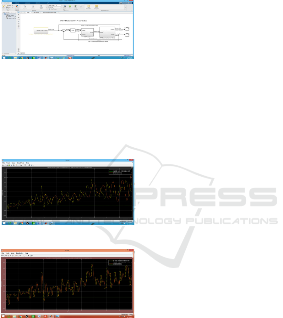
Figure 12: IRST model with PI controller
PI controller Parameter values:{ Kg=2000, Kf= 0.027,
Kt= 0.07, R=10, L=1e-05, Kd = 5, I/J=8.6, PI & AI value
are tunable}
During simulation, when we setup the parameter
of PI controller [proportional (P) =240 and Integral
(I) =180], the simulation result showed there much
error in target position and senor measured position
as figure 13..After tuning and simulation we found
that at PI Proportional (P) =1000 and Integral (I)
=500, there is less error found in actual position and
senor measured position as shown in figure 14.
Figure 13: Graph target position and senor measured
position[Proportional (P) =240 and Integral (I) =180]
Figure 14: Graph target position and senor measured
position [Proportional (P) =1000 and Integral (I) =500]
6 CONCLUSION
The proposed IRST system have IR channel, TV
camera, and LRF is installed in a single optical
window with two different signal processer, first IR
signal processor use for IR signal processing in IR
channel and second video signal processor for video
signal in Thermal/ video channel. The
communication between IRST CPU (ICPU) with
aircraft system done by using two type of bus
protocol. The IR signal processor use ARINC
429/1535b bus protocol and video processor use
ARINC 8181 bus protocol under control and
supervision ICPU. The Proposed modification in the
IRST system improve the performance, reduce the
size, and weight that is basic need of fighter aircraft.
The simulation result shows, that the Tracker
JPDA and TOMHT with IMM filter tracks
maneuvering targets more precisely and did not
break or lose the track even during the turns and in
the ambiguous region. The targets are more precisely
tracked during the turn and are sufficiently separated
in the ambiguity region However, the runtime for a
tracker TOMHT is significantly longer than using
tracker JPDA and computational data is less hence
required less memory space than tracker JPDA.
REFERENCES
Yilmaz, A., Shafique, K. and Shah, M. (2003). Target
tracking in airborne forward looking infrared imagery.
Elsevier Science.
Nengli, D., Qi J. G., and Jiaguang, M. (2001). New
approach to detect dim moving point targets based on
motion analysis. SPIE.
Yang, Hi.(2015). Detection and Tracking of Infrared Dim
Small Image Sequence Moving Target. The Open
Automation and Control Systems Journal.
Blom, H.,and Bar-Shalom, Y.(1988). The interacting
multiple model algorithm for systems with Monrovian
switching coefficients. IEEE Transactions on
Automatic Control.
Konstantin, P., Udvarev A., and Semerdjiev T.(2003). A
Study of a Target Tracking Algorithm Using Global
Nearest Neighbor Approach. InternationalConference
on Computer Systems and Technologies.
Tchango, A. F., Thomas. V., Buffet, O., Dutech, A., and
Flacher F., Tracking Multiple Interacting Targets
Using A Joint Probabilistic Data Association Filter.
Thales Services SAS Company.
Blackman, S.S. (2004). Multiple Hypothesis Tracking for
Multiple Target Tracking. IEEE, A&E Systems
Magazine.
Li, Q., Liu L., and Tang S.(2017). Composite Axis Control
System Development of Airborne Electro-Optical
Platform. IEEE 8th International Conference
Koretsky G.M., Nicoll J. F., and Taylor M.S.(2013). A
tutorial on Electro-optical / Infrared (EO/IR) theory
and systems. Institute of Defense Analysis (IDA).
Mazor, E., Averbuch, A., Bar-shalom, Y., Dayan,
J.(1998). Interacting multiple model in target tracking:
a survey. IEEE Trans. Aerospace.
ICACSE 2021 - International Conference on Advanced Computing and Software Engineering
210

Srivastava H.B., Limbu Y. B., Saran R., and Kumar
A.(2007). Airborne infrared search and track system.
Defense Science Journal.
Gaitanakis G.K., Vlastaras A., Limnaios N. V.G and
Zikidis K.C.(2019). Infrared Search & Track Systems
as an Anti-Stealth Approach. Journal of Computations
& Modeling.
Sabatini M. R., and Richardson M. A.(2010). Airborne
Laser Systems Testing and Analysis.,Airborne Laser
Systems Testing and Analysis (AGARD) / NOTO,
Flight Test Techniques Series.
Williams G.M., and Huntington A. (2018). Laser
rangefinder Effective Range. VoxtelInc, Technical
note.
Chen S.T. L., Yang J., and Hao J.(2011). A Novel
Algorithm of Maneuvering Target Tracking based on
AIMM-CKF.International Conference on Electronic &
Mechanical Engineering
Nivedita, Chawla P.(2015). Object Tracking in Simulink
using Extended Kalman Filter. International Journal of
Advanced Research in Computer and Communication
Engineering.
Detection and Tracking Techniques for Infrared Searching and Tracking System with Robust Control System
211
