
The Influence of the Gear Reduction Ratio on the Free-floating Space
Manipulator’s Dynamics
Mateusz Wojtunik
a
and Karol Seweryn
b
Centrum Badań Kosmicznych Polskiej Akademii Nauk (CBK PAN), Warsaw, Poland
Keywords: Space Robotics, Free-floating Manipulators, Gear-equipped Space Manipulators, Gear Reduction Ratio.
Abstract: Utilisation of space manipulator mounted on the satellite is one the main methods for the proposed Active
Debris Removal and On-Orbit Servicing missions. Precise numerical models of the manipulator’s joint are
very important as its dynamics has a strong effect on the behaviour of the system including the base where it
is mounted. One of aspects that can be considered is the extension of manipulator’s dynamical equations with
gear kinematic constraints. To achieve this goal, dynamical equations of motion for planar 3DoF free-floating
manipulator with gear kinematic constraints are presented in this paper. Open-loop analysis is performed to
form conclusions concerning the influence of the gear reduction ratio on space manipulator’s dynamics.
Torques required to perform end-effector straight line trajectory are evaluated using inverse dynamics path
planning algorithm and then utilised as motor driving torques for different gear reduction ratios. It appears
that the gear reduction ratio influences the system mass matrix nonlinearly causing the end-effector trajectory
to deviate from the straight line. These deviations are already observed for relatively low gear reduction ratios.
1 INTRODUCTION
Orbital robotics is becoming the field of research in
demand for the case of future Active Debris Removal
(ADR) technologies and On-Orbit Servicing (OOS)
missions (NASA, 2010). Increasing number of space
debris poses an important issue as collisions
probability ascends. It is projected that removing
space debris will help to maintain the number of space
objects at relatively constant value (Liou, 2011). In
addition, studies suggest that ADR and OOS missions
will be economically feasible (Sullivan and Akin,
2012). European Space Agency stated that one of its
main four goals is to widen contribution of European
consortia in space debris removal development before
2030 (ESA, 2019).
Space manipulators will have a significant role in
terms of ADR technologies development. Space
debris are most commonly noncooperative, thus
unmanned autonomous systems are needed to
perform the capture manoeuvre. There has already
been a lot of research done considering utilisation of
space manipulator for ADR. One of them is the
e.Deorbit mission designed to capture Envisat
a
https://orcid.org/0000-0002-0234-2368
b
https://orcid.org/0000-0002-4372-0900
satellite (Estable et al., 2020). Another mission that is
worth mentioning is DARPA’s Orbital Express
(Ogilvie, Allport, Hannah and Lymer, 2008). This
project led to succesful demonstration of capture
manoeuver of NEXTSat satellite using 6DoF robotic
arm.
Utilisation of free-floating manipulators poses a
lot of advantages in terms of designing ADR or OOS
missions. One of them is their high Technology
Readiness Level (TRL). Moreover, they are realtively
easy to be tested on ground in comparison to e.g. net
capturing (Shan, Guo and Gill, 2016). However,
space manipulators require designing complex
control algorithms taking extereme work
environment into the consideration (Siciliano and
Khatib, 2008). First challenge appears as space
manipulators are characterised with free-floating base
that moves via reaction forces and torques induced by
manipulator’s motion. Free-floating base is widely
considered in terms of path planning algorithms.
Numerous trajectory planning methods are presented
in literature, e.g. considering nonlinear optimisation
(Lampariello, 2010), control torque minimisation
(Rybus, Seweryn and Sąsiadek, 2016) or obstacles
282
Wojtunik, M. and Seweryn, K.
The Influence of the Gear Reduction Ratio on the Free-floating Space Manipulator’s Dynamics.
DOI: 10.5220/0010556502820289
In Proceedings of the 18th International Conference on Informatics in Control, Automation and Robotics (ICINCO 2021), pages 282-289
ISBN: 978-989-758-522-7
Copyright
c
2021 by SCITEPRESS – Science and Technology Publications, Lda. All rights reserved
avoidance (Rybus and Seweryn, 2015). In addition,
capture manoeuver analysis has to concern contact
dynamics between the gripper and the client satellite
(Korf, 1982).
Finally, joint dynamics have a much stronger
effect on the system behaviour than it is observed for
manipulators working on the Earth. This poses the
need for designing precise numerical models of the
joint. One of the most popular aspects cosindered in
mathematical models is joint flexibility. This is
exteremely important as it induces additional
eigenfrequencies of the system causing the end-
effector to oscillate or lose stability (Sąsiadek, 2013).
Flexible-joint manipulator models are widely
described with different model configurations. Fixed-
base assumption is considered by Ulrich and Sąsiadek
(2012). Analysis for the maximum load of flexible-
joint manipulators is performed by Korayem, A.,
Irani, Babaee and Korayem, M. (2017). Free-floating
base is introduced e.g. by Yu (2015). In addition,
wheeled mobile manipulators are also analysed
(Korayem and Ghariblu, 2003). Moreover, flexible
links are often considered (Korayem, Rahimi and
Nikoobin, 2011). The analysis is also extended with
joint friction (Qingxuan, 2008), (Liu, Li, Wang and
Cai, 2015). The generalised mathematical model for
the free-floating flexible-joint manipulator is
described by Nanos and Papdopoulos (2015).
Another important aspects are both dynamics and
kinematics of manipulator gears. Despite the fact that
including the gear kinematic constraint for space
manipulators is not widely considered in the
literature, it is often introduced in the flexibility
models e.g. (Qingxuan, 2008) and (Nanos and
Papadopoulos, 2015). However, there is no
straightforward analysis of the influence of the gear
on the dynamics of the free-floating manipulator. In
this paper we provide an explanation for
modifications arising from extending space
manipulator’s mathematical model with gear
constraints. This also shows the importance of the
common model assumption that driving torques are
applied in manipulator’s joints directly to its links.
Consideration of additional effects could pose
conclusions for the choice of the control algorithm. In
addition, including precise numerical model of the
joint in the control algorithm may be beneficial for
the control quality.
In this paper we present dynamical equations for
the gear-equipped planar 3DoF space manipulator
with control torques applied to motors. Open-loop
analysis is performed to pose conclusions for the
influence of the gear reduction ratio on the dynamical
behaviour of the system. The paper is organised as
follows. Dynamical equations of the analised system
are presented in Section 2, whereas the simulation
results are described in Section 3. Section 4 concludes
the paper with a summary.
2 DYNAMICAL EQUATIONS
In this section, equations for the planar 3DoF free-
floating space manipulator are introduced as well as
the extension of the gear kinematic constraint is
presented. The model is based on equations presented
by Rybus et al. (2016) and originated from the
algorithm introduced by Seweryn and Banaszkiewicz
(2008).
2.1 Planar 3DoF Free-floating Space
Manipulator
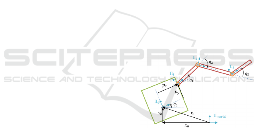
Coordinate systems and state variables are defined on
the schematic view and shown in Figure 1.
Generalised coordinates vector of the system 𝐪
includes base X and Y position components and its
orientation as well as manipulator’s joint angles:
𝐪=
𝑥
𝑦
𝑞
𝑞
𝑞
𝑞
(1)
Figure 1: Schematic view of the planar 3DoF satellite-
manipulator system.
We follow the Lagrange formalism to achieve the
set of dynamical equations of the system (Schaub and
Junkins, 2002). The generalised forces vector 𝐐 for
the analysed system is given by:
𝐐=
𝐹
𝐹
𝜏
𝜏
𝜏
𝜏
(2)
where 𝐹
and 𝐹
denote X and Y components of the
force acting on the base centre of mass, respectively,
𝜏
denotes torque acting on the base centre of mass,
whereas 𝜏
, 𝜏
and 𝜏
are joint torques.
When the satellite-manipulator system is in the
proximity of the client satellite, base control system
is considered to be turned off, therefore the first three
The Influence of the Gear Reduction Ratio on the Free-floating Space Manipulator’s Dynamics
283
components of 𝐐 are equal to zero. The consequence
of this assumption is that the system has conserved
total momentum and angular momentum – joint
driving torques are of internal nature. Moreover, it is
widely assumed that the space manipulator does not
have potential energy as gravity forces are negligible,
thus Lagrange function becomes the total kinetic
energy of the system calculated as:
𝐸
=
1
2
𝑚
𝑥
+𝑦
+
1
2
𝐼
𝑞
+
+
1
2
𝑚
𝐯
𝐯
+
1
2
𝐼
𝜔
(3)
where 𝑥
and 𝑦
denotes components of the linear
velocity of the satellite centre of mass, 𝑞
denotes the
angular velocity of the satellite, 𝑚
denotes the mass
of the satellite and 𝐼
is the inertia of the satellite, 𝑚
denotes the mass of the 𝑖-th link and 𝐼
is the inertia
of the 𝑖-th link, whereas 𝐯
denotes the 𝑖-th link centre
of mass translational velocity vector and 𝜔
is the 𝑖-
th link angular velocity in Π
frame evaluated as:
𝜔
=𝑞
+𝑞
(4)
where 𝑞
denotes the angular velocity of 𝑗-th joint
with respect to the previous joint Π
.
The translational velocity vector of each link
centre of mass is derived from differentiating its
position components arising from kinematical
equations of the satellite-manipulator system. After
such derivation, the total kinetic energy of the system
(3) becomes dependent upon generalised coordinates
and velocities of the system. Thus, it can be
differentiated to expand the Euler-Lagrange
equations. This leads to the final formula for
dynamical equations of the free-floating manipulator
that can be expressed in the following form:
𝐌
𝐪
𝐪
+𝐂
𝐪,𝐪
𝐪
=𝐐
(5)
where 𝐌
𝐪
denotes a [6x6] system mass matrix that
satisfies the following relation:
𝐸
=
1
2
𝐪
𝐌
𝐪
𝐪
(6)
In (5) 𝐂
𝐪,𝐪
denotes a [6x6] centrifugal and
Coriolis forces matrix defined as:
𝐂
𝐪,𝐪
=𝐌
𝐪,𝐪
1
2
𝜕
𝜕𝐪
𝐌
𝐪
𝐪
(7)
where 𝐌
𝐪,𝐪
denotes the time derivative of the
mass matrix.
Analytical equations posing each element of
𝐌
𝐪
and 𝐂
𝐪,𝐪
are presented in (Wojtunik, 2020).
Derived relations allow to define dependencies of
joints driving torques for the given satellite-
manipulator system trajectory defined in the
generalised coordinates. Equation (5) can be finally
solved for 𝐪
to form a set of differential equations of
the system:
𝐪
=𝐌
𝐪
𝐐𝐂
𝐪,𝐪
𝐪
(8)
2.2 Gear Kinematic Constraint
Set of equations derived in the previous section
assumed that manipulator joints are the ideal source
of driving torques. However, there are many
modelling aspects that can extend the model. One of
them is the kinematic constraint of the gear. In this
section the approach for modelling gear kinematics is
presented.
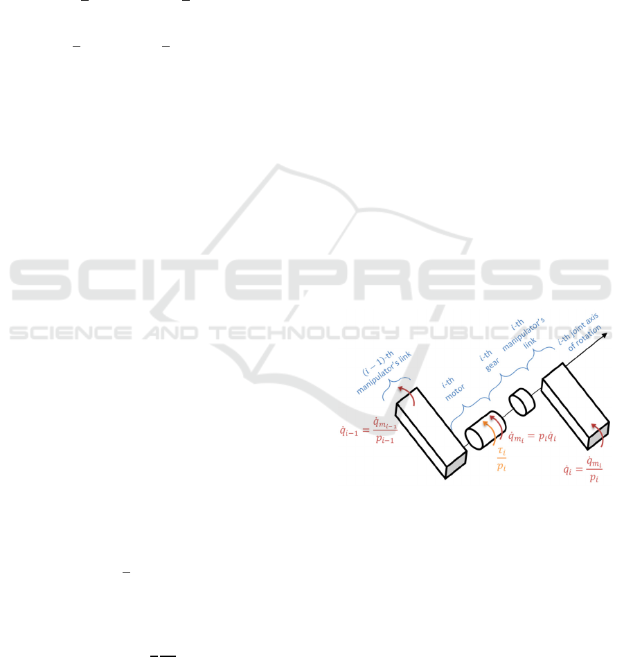
In order to introduce the gear kinematic
constraint, the additional body – motor – must be
considered to be rotating in each joint. The schematic
view of the joint equipped with gear is depicted in
Figure 2. 𝑖-th motor and 𝑖-th link are considered to be
rotating around the same axis. In contrast to
discussion in the previous section, the driving torque
will now be applied to the motor instead of being
directly applied to the link.
Figure 2: Schematic view of manipulator joint equipped
with gear.
Motors and links are connected via gear which
leads to the following kinematic constraint:
𝑞
=𝑝
𝑞
(9)
where 𝑞
denotes motor angular velocity with
respect to the previous joint Π
(similarly to 𝑞
) and
𝑝
denotes 𝑖-th gear reduction ratio taking values
greater or equal to 1.
The following approach of deriving set of
equations for the free-floating manipulator equipped
with gears will take advantage of relations posed in
ICINCO 2021 - 18th International Conference on Informatics in Control, Automation and Robotics
284

the previous section. Total kinetic energy of the
system (3) must be expanded with total motors’
kinetic energy defined below. It is assumed that motor
mass is included in the link mass, therefore only
rotational kinetic energy is considered:
𝐸
=𝐼
𝜔
(10)
where 𝐼
denotes the inertia of the 𝑖-th motor and
𝜔
denotes the 𝑖-th motor angular velocity in Π
frame defined as:
𝜔
=
⎩
⎨
⎧
𝑞
+𝑞
,𝑖=1
𝑞
+𝑞
+𝑞
,𝑖>1
(11)
Algebraic constraint (9) allows us to decrease the
system order by posing 𝑞
as a function of 𝑞
or vice
versa. It is more intuitive to choose motor variables
as the generalised coordinates because driving
torques are no longer applied to links. Thus, the
generalised coordinates vector becomes:
𝐪
=
𝑥
𝑦
𝑞
𝑞
𝑞
𝑞
(12)
Equations (3) and (10) form the total kinetic
energy of the system dependent upon 𝐪
and 𝐪
that
is substituted to the Euler-Lagrange equation.
Similarly to the approach presented in section 2.1,
required derivatives are calculated to form a final set
of dynamical equations of the system:
𝐌
𝐪
𝐪
+𝐂
𝐪
,𝐪
𝐪
=𝐐
(13)
where 𝐐
is the generalised forces vector containing
motor driving torques scaled using gear reduction
ratios:
𝐐
=
𝐹
𝐹
𝜏
𝜏
𝑝
𝜏
𝑝
𝜏
𝑝
(14)
Finally, equation (13) is solved for 𝐪
:
𝐪
=𝐌
𝟏
𝐪
𝐐
+𝐂
𝐪
,𝐪
𝐪
(15)
Analytical relations for 𝐌
𝐪
and 𝐂
𝐪
,𝐪
are too complex to be presented. Instead, a brief
description of deviations between obtained models is
provided below. The mass matrix as well as the
Coriolis matrix of the satellite-manipulator system
equipped with gears differ from matrices depicted in
(5). As a result of introducing gear constraint (9)
inertia components of links will now be scaled by
gear reduction ratios 𝑝
. 𝑖-th link inertia and mass
components located within the main diagonal of
𝐌
𝐪
are scaled by 𝑝
, whereas outside the main
diagonal they are scaled by 𝑝
. In addition, as
multiple-joint manipulator is considered, some
components of the mass matrix can be scaled by the
multiplication of different gear reduction ratios.
Similarly, some components of 𝐂
𝐪
,𝐪
are
dependent upon gear reduction ratios. The above-
mentioned observations pose neuralgic nonlinear
influence of 𝑝
on the dynamics of the system which
will be analysed in the next section.
3 NUMERICAL SIMULATIONS
The influence of the gear reduction ratio on the
dynamics of the free-floating space manipulator will
be analysed in this section. The discussion will
concern the open-loop analysis for the straight line
trajectory of the manipulator’s end-effector.
In order to find required driving torques for the
given end-effector trajectory, we follow the inverse
dynamics approach for path planning introduced by
Basmadji, Seweryn and Sąsiadek (2020). First of all,
required generalised coordinates, velocities and
accelerations to achieve end-effector straight line
trajectory are calculated for the given initial satellite-
manipulator system’s state. The initial momentum
and angular momentum of the system is set to be zero.
Manipulator’s parameters are set to reflect the
prototype built in the Space Research Centre of the
Polish Academy of Sciences (Basmadji, Chmaj,
Rybus and Seweryn, 2019) and are shown in Table 1.
The end-effector is chosen to travel 0.4 m along the
X axis (from 1.5 m to 1.1 m), maintaining constant Y
position (0 m) and orientation (
rad) expressed in
Π
. Then, equation (5) is used to evaluate the
desired driving torques required to achieve the
planned trajectory. The trajectory (red line) of the
manipulator is shown in Figure 3. Computed driving
torques in each joint are presented in Figure 4.
Driving torques required to perform straight line
trajectory are then scaled with gear reduction ratios
(14) and used to actuate the manipulator model with
gears (15). Numerical model of the satellite-
manipulator system is designed in Matlab/Simulink
with the use of Simscape SimMechanics library. This
model poses the system of identical mathematical
description as in (15). The model is solved with IV
order Runge-Kutta method (ode4). The integration
time step is set to 0.01 s.
It is important for the gear-equipped manipulator
model to maintain the same total inertia of the system
as the reference model. Thus, if nonzero motor inertia
The Influence of the Gear Reduction Ratio on the Free-floating Space Manipulator’s Dynamics
285

is introduced, respective link inertia has to be
decreased in a specific manner. For following
simulations, each motor inertia is set to 10
-5
kgm
2
. In
addition, it is assumed that gear reduction ratios in all
joints are equal.
Figure 3: Analysed end-effector trajectory.
Figure 4: Computed driving torques.
Table 1: Satellite-manipulator system parameters.
Parameter Value
Satellite mass 64.859 kg
Satellite inertia 2.695 kgm
2
Manipulator mounting point [0.370, 0.001] m
Link 1 mass 2.913 kg
Link 1 inertia 0.091 kgm
2
Link 1 length 0.449 m
Link 1 centre of mass position [0.181, 0] m
Link 2 mass 2.646 kg
Link 2 inertia 0.081 kgm
2
Link 2 length 0.450 m
Link 2 centre of mass position [0.200, 0] m
Link 3 mass 1.699 kg
Link 3 inertia 0.022 kgm
2
Link 3 length 0.355 m
Link 3 centre of mass position [0.103, -0.002] m
The following values of gear reduction ratio are
analysed: 1, 1.05, 1.1, 1.25, 1.5, 2.5, 5 and 10. End-
effector trajectories for each simulation are compared
in Figure 5. Final configurations for the manipulator
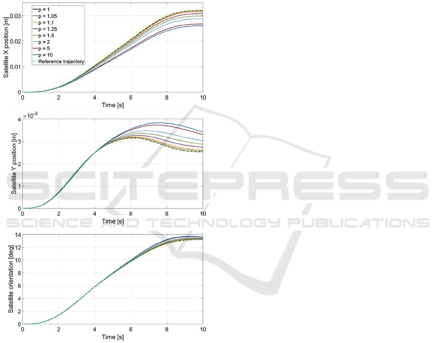
(excluding 𝑝=1) are presented in Figure 6.
Manipulator’s joint velocities are presented in Figure
7. Base position components and orientation are
shown in Figure 8. In addition, end-effector’s position
errors in the final configuration are presented in Table
2, where X and Y errors are derived as the difference
between the respective position components in
comparison to the reference case. The error norm is
calculated as the square-root of the sum of squares of
the above-mentioned errors.
It is observed that if the gear reduction ratio is
equal to one then the model acts numerically identical
to the reference case – mass matrices for both models
are indistinguishable.
The analysis shows that the straight line trajectory
is not projected well even for relatively low gear
reduction ratios – the error norm surpasses 5 cm
already for 𝑝=1.25. The Y component error for 𝑝=
10 reaches over 25 cm whereas the X component
error exceeds 10 cm. These errors are observed
because manipulator joint trajectories are not equal to
desired ones that result from the reference model.
Another consequence is observed in Figure 8 where
satellite position and orientation deviations are seen.
The reason behind these results is related to gear
reduction ratio’s appearance in the mass matrix of the
system. As stated in the previous section, this
parameter scales the matrix nonlinearly – some inertia
components are scaled with 𝑝
, others with 𝑝 and
there is also a group of components that are not scaled
at all. The nonlinear nature of this influence is well
observed in Figure 6 where e.g. deviations between
simulations with 𝑝=10 and 𝑝=5 have different
magnitude than differences between simulations with
𝑝=2 and 𝑝=1. It appears that torque signals that
have to be applied to motors in order to provide
straight line trajectory have different shape than those
calculated for the reference model. In addition, the
above-mentioned scaling is quite extreme, as e.g. 𝑝=
5 can decrease link inertia seen by the motor even 25
times. If we were to provide that links’ velocities are
exactly the same as it appears for the planned
trajectory, the end-effector would project the straight-
line independently of 𝑝, because it is assumed that the
overall inertia of the joint is identical for both
Figure 5: Comparison of end-effector trajectories for
simulations with different gear reduction ratios.
ICINCO 2021 - 18th International Conference on Informatics in Control, Automation and Robotics
286
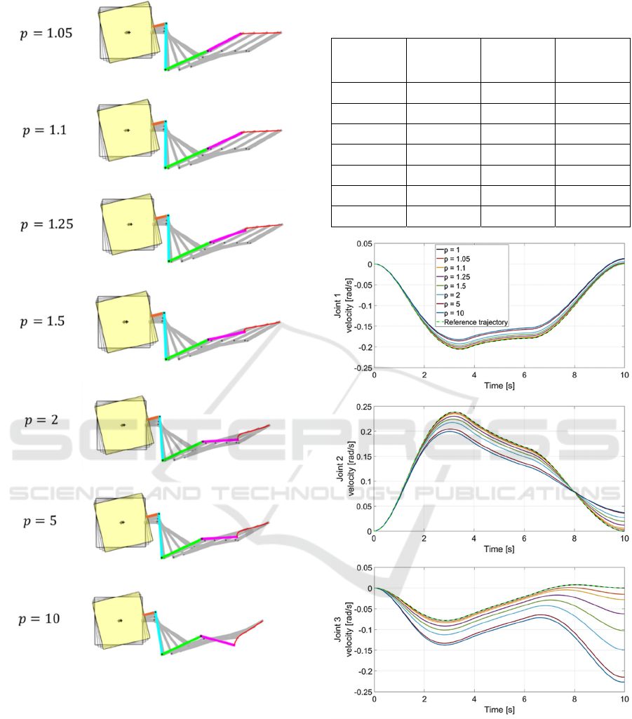
Figure 6: End-effector trajectories for simulations with
different gear reduction ratios.
reference and extended model. However, achieving
the same joint velocities require different torque
signals as equation (13) differs from (5). This leads to
a conclusion that in the closed-loop case based on
equation (5) control signals from space manipulator
controller are obliged to compensate errors induced
by the gear influence on the dynamics of the system.
These observations pose an important issue that arises
from the assumption of applying driving torques
directly to manipulator’s links. It appears that this
Table 2: End-effector position errors in the final
configuration for different gear reduction ratios.
Gear
reduction
ratio
X position
error [m]
Y position
error [m]
Error
norm [m]
1.05 0.0105 -0.0127 0.0165
1.1 0.0196 -0.0246 0.0314
1.25 0.0404 -0.0555 0.0686
1.5 0.0615 -0.0947 0.1129
2 0.0810 -0.1447 0.1658
5 0.0991 -0.2309 0.2513
10 0.1037 -0.2544 0.2748
Figure 7: Joint velocities for simulations with different gear
reduction ratios.
supposition causes driving torques to differ from
signals that could be required to perform specific task
by the satellite-manipulator system designed for
space mission. Therefore, it is concluded that precise
joint models can provide greater verifiability of the
simulation tool as it magnifies dynamical behaviour
The Influence of the Gear Reduction Ratio on the Free-floating Space Manipulator’s Dynamics
287
caused by gears. It can also be beneficial to include
such aspects in the control system.
In addition, it is interesting to observe the final
manipulator’s configurations seen in Figure 5. For
instance, for the highest analysed gear reduction ratio
the third link has much more deviated position than it
is seen for other simulation cases. The nonzero third
joint velocity at the end of the simulation (Figure 7)
causes the end-effector trajectory to deviate towards
negative Y positions.
Figure 8: Satellite position and orientation for simulations
with different gear reduction ratios.
4 CONCLUSIONS
The modified free-floating satellite-manipulator
system model with the kinematic gear constraints
allowed to pose conclusions regarding the influence
of the gear reduction ratio on the dynamics of the
system. Lagrange functions for both reference and
newly discussed model were used to derive
dynamical equations of the system and observe
differences in the system mass matrix components
induced by the constraint. It appears that both mass
matrix and Coriolis and centrifugal forces matrix are
dependent nonlinearly upon the gear reduction ratio.
The influence of this parameter on the dynamics of
the system was analysed by applying reference
driving torque signals to actuate the extended model.
It turned out that the planned straight line trajectory is
not projected well by the model concerning joint
gears. It presents the importance of modelling gear
kinematic constraints as the control system will be
working under different circumstances than it is
posed by the reference model. Designing a precise
model of space manipulator’s joint is therefore
extremely important to provide greater verifiability of
the simulation tool. The future work may include
analysis of motor driving torques in the closed-loop
system for the manipulator equipped with gears. In
addition, the derived model could be extended with
additional aspects such as joints’ or links’ flexibility,
joint friction or dynamics of the gear.
ACKNOWLEDGEMENTS
This paper was partially supported by the Polish
National Centre for Research and Development in the
frame of the LIDER X programme (project no.
LIDER/19/0117/L-10/18/NCBR/2019).
The Author would like to thank Dr. Tomasz
Rybus from the Space Mechatronics and Robotics
Laboratory at Centrum Badań Kosmicznych Polskiej
Akademii Nauk (CBK PAN) for his helpful
suggestions.
REFERENCES
Basmadji, F. L., Chmaj, G., Rybus, T. and Seweryn, K.
(2019). Microgravity testbed for the development of
space robot control systems and the demonstration of
orbital maneuvers. Photonics Applications in
Astronomy, Communications, Industry, and High-
Energy Physics Experiments, Wilga, Poland.
Basmadji, F. L., Seweryn, K. and Sąsiadek, J. Z. (2020).
Space robot motion planning in the presence of linear
and angular momenta. Multibody System Dynamics
(vol. 50, pp. 71-96).
ESA’s Technology Strategy (2019). European Space
Agency, v1.1.
Estable, S., Pruvost, C., Ferreira, E., Telaar, J., Frunhert,
M., Imhof, C., Rybus, T., et al. (2020). Capturing and
deorbiting Envisat with an Airbus Spacetug. Results
from the ESA e.Deorbit consolidation phase study.
Journal of Space Safety Engineering (vol. 7, pp. 52-66).
ICINCO 2021 - 18th International Conference on Informatics in Control, Automation and Robotics
288

Korayem, A. H., Irani, M., Babaee, H. and Korayem, M. H.
(2017). Maximum load of flexible joint manipulators
using nonlinear controllers. Robotica (vol. 35, no. 1, pp.
119-142).
Korayem, M. H., Rahimi, A. and Nikoobin, A (2011). Path
Planning of Mobile Elastic Robotic Arms by Indirect
Approach of Optimal Control. Journal of Advanced
Robotic Systems (vol. 8, no. 1, pp. 10-20).
Korayem, M. H. and Gariblu, H. (2003). Maximum
Allowable Load on Wheeled Mobile Manipulators
Imposing Redundancy Constrains. Robotics and
Autonomous Systems (no. 44, pp. 151-159).
Korf, R. E. (1982). Space robotics. Carnegie-Mellon
University, The Robotics Institute.
Lampariello, R. (2010). Motion Planning for the On-orbit
Grasping of a Non-cooperative Target Satellite with
Collision Avoidance. 10
th
International symposium on
Artificial Intelligence, Robotics and Automation In
Space, Sapporo, Japan.
Liou, J. C. (2011). An active debris removal parametric
study for LEO environment remediation. Advances in
Space Research (vol. 47(11), pp. 1865-1876).
Liu, X., Li, H., Wang, J. and Cai, G. (2015). Dynamics
analysis of flexible space robot with joint friction.
Aerospace Science and Technology (vol. 47, pp. 164-
176).
Nanos, K. and Papadopoulos, G. (2015). On the dynamics
and control of flexible joint space manipulator. Control
Engineering Practise (vol. 45, pp. 230-143).
Ogilvie, A., Allport, J., Hannah, M. and Lymer, J. (2008).
Autonomous satellite servicing using the Orbital
Express Demonstration Manipulator System. 9
th
International Symposium on Artificial Intelligence,
Robotics and Automation in Space, Hollywood, USA.
On-orbit Satellite Servicing Study (2010). NASA,
Technical Report.
Qingxuan, J., Xiaodong, Z., Hanxu, S. and Ming, C. (2008).
Active Control of Space Flexible-Joint/Flexible-Link
Manipulator. IEEE Conference on Robotics,
Automation and Mechatronics, Chengdu, China.
Rybus, T. and Seweryn, K. (2015). Application of Rapidly-
exploring Random Trees (RRT) algorithm for trajectory
planning of free-floating space manipulator.
Proceedings of the 10th International Workshop on
Robot Motion and Control, Poznan, Poland.
Rybus T., Seweryn K. and Sąsiadek, J. Z. (2016).
Trajectory Optimization of Space Manipulator with
Non-zero Angular Momentum During Orbital Capture
Maneuver. AIAA Guidance, Navigation and Control
Conference, San Diego, USA.
Sąsiadek, J. Z. (2013). Space Robotics and its Challenges.
Aerospace Robotics. GeoPlanet: Earth and Planetary
Sciences, Springer (pp. 1-8).
Schaub, H. and Junkins, J. L. (2002). Analytical Mechanics
of Aerospace Systems. American Institute of
Aeronautics and Astronautics, Inc.
Seweryn, K. and Banaszkiewicz, M. (2008). Optimization
of the trajectory of a general free-flying manipulator
during the rendezvous maneuver. Proceedings of the
AIAA Guidance, Navigation, and Control Conference
and Exhibit (AIAA-GNC’2008), Honolulu, USA.
Shan, M., Guo, J. and Gill, E. (2016). Review and
comparison of active space debris capturing and
removal. Progress in Aerospace Sciences (vol. 80, pp.
18-32).
Siciliano, B. and Khatib, O. (2008). Springer Handbook of
Robotics, Springer.
Sullivan, B. and Akin, D. (2012). Satellite servicing
opportunities in geosynchronous orbit. Proceedings of
the AIAA SPACE 2012 Conference and Exposition,
Pasadena, USA.
Ulrich, S. and Sąsiadek, J. Z. (2012). Modelling and Direct
Adaptive Control of a Flexible-Joint Manipulator.
Journal of Guidance, Control, and Dynamics (vol.
35(1), pp. 25-39).
Wojtunik, M. (2020). Modelling and validation of space
robot’s joint. Master’s thesis (in Polish: Opracowanie i
walidacja modelu matematycznego złącza
manipulatora satelitarnego), Technical University of
Lodz.
Yu, X.-Y. (2015). Augmented robust control of a free-
floating flexible space robot. Journal of Aerospace
Engineering (vol. 229(5), pp. 947-957).
The Influence of the Gear Reduction Ratio on the Free-floating Space Manipulator’s Dynamics
289
