
Automatic 3D Object Recognition and Localization for Robotic Grasping
Bruno Santo, Liliana Ant
˜
ao
a
and Gil Gonc¸alves
b
SYSTEC, Research Center for Systems and Technologies,
Faculty of Engineering, University of Porto,
Rua Dr. Roberto Frias, 4200-465 Porto, Portugal
Keywords:
Robotics, Grasping, Object Pose Estimation, Object Recognition.
Abstract:
With the emergence of Industry 4.0 and its highly re-configurable manufacturing context, the typical fixed-
position grasping systems are no longer usable. This reality underlined the necessity for fully automatic
and adaptable robotic grasping systems. With that in mind, the primary purpose of this paper is to join
Machine Learning models for detection and pose estimation into an automatic system to be used in a grasping
environment. The developed system uses Mask-RCNN and Densefusion models for the recognition and pose
estimation of objects, respectively. The grasping is executed, taking into consideration both the pose and the
object’s ID, as well as allowing for user and application adaptability through an initial configuration. The
system was tested both on a validation dataset and in a real-world environment. The main results show that
the system has more difficulty with complex objects; however, it shows promising results for simpler objects,
even with training on a reduced dataset. It is also able to generalize to objects slightly different than the ones
seen in training. There is an 80% success rate in the best cases for simple grasping attempts.
1 INTRODUCTION
Object recognition and pose estimation are two of the
main topics in Computer Vision (CV), with an in-
creasing number of explored solutions over the last
few years. Despite being applied to several different
areas, from augmented reality to autonomous driving,
robotic grasping is one of these topics’ most critical
applications. The main focus in grasping is to enable
computer systems to process, analyze and, ultimately,
extract information or understanding of the objects to
grasp from a digital image. Traditionally, the focus
has been on using image processing techniques com-
bined with careful analysis and programming. Meth-
ods such as these can be used for grasp planning us-
ing shape primitives and previous knowledge of op-
timal grasping positions (Miller et al., 2003). This
has had improvements in performance and productiv-
ity for automation in the industry.
However, in this new reality of Industry 4.0, pro-
duction processes are increasingly oriented towards
product customization, demanding robotic solutions
to be more and more flexible. This is true espe-
cially in the context of Human-Robot Collaboration,
a
https://orcid.org/0000-0002-2903-0989
b
https://orcid.org/0000-0001-7757-7308
where human-robot teams need to perceive tasks the
same way between them. Humans are inherently good
at perceiving their environment and the objects sur-
rounding them, identifying their characteristics, posi-
tion, and deciding naturally where to grasp an object
and how much force to exert on it (Bicchi and Ku-
mar, 2000). For this reason, the main focus in the
latest grasping applications has been on increasing
reconfigurability and responsiveness (Saxena et al.,
2008). Using only typical hard-coded robotic solu-
tions where the objects’ positions are fixed, this real-
ity is not achievable due to a very restrictive imple-
mentation.
In the last decade, CV research has focused on ap-
plying image processing techniques in tandem with
Machine Learning (ML) and Deep Learning (DL)
models. Due to the convincing results that have been
achieved in this scope, there is an increasing trend to-
wards the implementation of DL algorithms in robotic
grasping applications (Lenz et al., 2015). This en-
ables robots to use cameras to perceive their environ-
ment and reason about tasks more intelligently. DL
models are often applied in pose estimation, enabling
fully automatic and efficient grasping. In order to im-
prove robotic grasping, besides localization, provid-
ing object recognition can also be advantageous. By
416
Santo, B., Antão, L. and Gonçalves, G.
Automatic 3D Object Recognition and Localization for Robotic Grasping.
DOI: 10.5220/0010552704160425
In Proceedings of the 18th International Conference on Informatics in Control, Automation and Robotics (ICINCO 2021), pages 416-425
ISBN: 978-989-758-522-7
Copyright
c
2021 by SCITEPRESS – Science and Technology Publications, Lda. All rights reserved

giving the object’s semantic class, the system can then
adapt the grasping to the object’s characteristics. For
instance, the gripping strength the manipulator can
apply without causing damage to the object, can be in-
ferred from its classification, or even choosing which
object to pick out in a group of objects by its charac-
teristics.
There are already many object detection and clas-
sification systems, as well as pose estimation models
for grasping. However, very few showing the benefits
of joining both approaches for a more complete and
autonomous grasping, much less fully automated or
based on only camera frame information (both RGB
and/or depth). Therefore, the challenge tackled in this
paper is to explore and develop a real-time intelligent
and fully automated system that joins both localiza-
tion and categorization of objects in 3D for grasping,
derived from the analysis of data from a stereo vision
camera system.
In short, our approach allows for the following
contributions:
• It combines both detection and pose information
(using Mask-RCNN and Densefusion), allowing
for grasping adapted to each type of object;
• User customization, allowing for the use of a con-
figuration file with optimal grasping points for
each object, increasing user and application adapt-
ability (as well as accuracy and speed);
• The system runs entirely automatically, being
able to detect movements and differences between
video frames, which allows for more optimized
calculations and inference on each frame;
• The use of transfer learning is combined with a
smaller dataset for real-world testing;
2 RELATED WORK
2.1 Object Detection and Recognition
There have been two main approaches for object de-
tection in recent years: region based detectors and
single-shot detectors. The former utilizes some kind
of region proposal algorithm, followed by a bound-
ing box regressor and a classifier. The latter tries to
speed up computation by combining these methods
into a single network. Of the region based detec-
tors, the main models are Faster-RCNN (Ren et al.,
2017), and R-FCN (Dai et al., 2016). Faster-RCNN
utilizes a region proposal neural network, followed
by a classification layer to label the proposed regions
and a regression layer for the bounding-box coordi-
nates (Ren et al., 2017). R-FCN shares the same ar-
chitecture for region proposal generation. However,
it applies another layer after the proposal to obtain
position-sensitive score maps for each object class.
These maps are used to classify the object in each
region. In terms of bounding-box regression, it fol-
lows the same architecture as the previous model (Dai
et al., 2016).
When it comes to single-shot detectors, the dom-
inant models are SSD (Liu et al., 2016) and YOLO
(presented initially in (Redmon et al., 2016)). SSD
eliminates the need for region proposal methods by
generating feature maps at multiple scales and us-
ing convolutional kernels on default-sized bounding-
box proposals to compute class probability scores and
bounding-box size offsets (Liu et al., 2016). YOLO
divides its input image into a grid, and each cell is re-
sponsible for predicting anchor boxes for the objects,
as well as class probabilities (Redmon et al., 2016),
(Redmon and Farhadi, 2017), (Farhadi and Redmon,
2018). When speed is a principal concern, the single-
shot detectors are best, with YOLO being the fastest
of the two. However, for accuracy, the best model is
R-FCN, although it is too slow for most real-time ap-
plications. For this reason, YOLO presents the best
trade-off between accuracy and speed, for bounding-
box detection.
2.2 Object Pose Estimation
The main deep learning approaches to pose estimation
are PoseCNN (Xiang et al., 2018), DPOD (Zakharov
et al., 2019), PVNet (Peng et al., 2019), Densefu-
sion (Wang et al., 2019) and HybridPose (Song et al.,
2020). Some models use only RGB image features for
their predictions, while others use depth data. Most
models also apply a refinement step on the predic-
tion to make it more accurate, using depth data. The
following shows the most important characteristics of
these models.
PoseCNN decouples pose estimation into three
separate tasks: semantic labeling, 3D translation es-
timation, and 3D rotation regression, enabling the
network to model how each task relates to the oth-
ers (Xiang et al., 2018). As for DPOD, it comprises
a model composed of three blocks: correspondence
block, pose block, and a final pose refinement block
(Zakharov et al., 2019).
PVNet (Peng et al., 2019) looks to turn its model
more robust to occlusion and truncation. The main
idea is to predict, for each pixel in an object, the unit
vectors from that pixel to all the keypoints in the ob-
ject (Peng et al., 2019). Densefusion is one of the
Automatic 3D Object Recognition and Localization for Robotic Grasping
417

few to take advantage of depth information from the
first stage of the model by fusing RGB data and point
cloud values on a per-pixel basis, utilizing a dense fu-
sion algorithm (Wang et al., 2019).
HybridPose (Song et al., 2020) differentiates itself
from other models by adding more intermediate rep-
resentations, enabling its model to work better in oc-
clusion situations and having more information about
the geometrical characteristics of the object. The in-
termediate representations used are: keypoints, edge
vectors, and dense pixel-wise symmetry correspon-
dences (Song et al., 2020).
As for the pose refinement algorithms typically
used, Iterative Closest Point (ICP) (Rusinkiewicz and
Levoy, 2001) tends to be the most used method. This
algorithm tries to align a set of input points to a refer-
ence set, given some error metric, in an iterative man-
ner. DeepIM - presented in (Li et al., 2019) - is an-
other algorithm, which takes as inputs the object 3D
model and the image of the object and renders an im-
age based on the 3D model. The rendering is com-
pared to the original image using an artificial neu-
ral network (ANN) in an iterative manner. In most
benchmarking datasets, the combination of PoseCNN
and DeepIM tends to achieve the most accurate re-
sults, however it is slower than other models, due to
the many iterations it uses. Densefusion is the second
most accurate model overall, except when it comes
to occlusion, where HybridPose tends to achieve the
best results, due to its use of multiple intermediate
representations.
3 SYSTEM OVERVIEW
For the purpose of creating a solution able to detect
and locate objects for automatic grasping, several dif-
ferent modules were joined. The complete general
architecture of the system is presented in Figure 1,
where the data flow can also be seen.
To capture the work-space, a Data Acquisition
module using a ZED stereo-vision camera was imple-
mented. After visual data acquisition, the Computer
Vision module (Object Detection/Segmentation plus
Pose Estimation) processes the received information
(RGB frames and depth maps) to obtain the object’s
6D coordinates (three for translation (Point Coord.),
and three for rotation (Gripper Rot.)), as well as iden-
tification (Object ID).
The Computer Vision Module was implemented
in a Python script that contains a MQTT (MQ Teleme-
try Transport) client. This client is connected to a
MQTT broker located inside the 3D printed gripper
controller (a Raspberry Pi). In order to send the infor-
mation for the robot, the 6D pose and object’s ID are
published as messages in two different MQTT topics:
”topic/pose” and ”topic/id”.
A Robot/Grasping API was used on the robotic
system’s side, also implemented in Python with a
MQTT Client. In this API, the client subscribes to the
pose and id topics, receiving from the broker every
published message in those topics. With the object’s
pose, the API is then able to send a direct ”MOVE”
command to the robotic manipulator controller via
TCP/IP. The robot controller then sends back a signal
when arriving at the defined position. After receiving
this feedback, the system knows the grasping itself
can be performed.
To achieve this, the Robot API generates a clos-
ing percentage for the gripper (% Closure), ranging
from 0 (totally open) to 100 (totally closed), based on
the object’s ID. This percentage is then published in a
MQTT topic (”topic/gripper”), triggering the gripper
to close or open accordingly and grasp the object in
question. After finishing grasping, the gripper pub-
lishes a message to provide the API with that info,
which then can send a new ”MOVE” command for
the object’s goal position after grasping. Finally, the
controller sends the finished movement signal. The
API publishes a message for the gripper to open. The
gripper publishes a message indicating that it finished
the task to the vision system, concluding the process.
3.1 Operation Modes
As can be seen in Figure 2, the complete system can
be run in two different modes: Configuration mode
and Normal mode. In the first mode, the objective is
to create three configuration files that will be used by
the system in normal operation. The second mode is
responsible for the interaction with the system and the
calculations for pose estimation.
3.1.1 Configuration Mode
The Configuration mode has three steps and is in-
tended to be used by a technician. Its purpose is to
ease the creation of configuration files that are re-
quired and loaded into Normal mode. These files are
more practical and increase the efficiency and mem-
ory optimization of the program. The first step in
this mode is to input a set of matching points coordi-
nates, both in the camera coordinate frame and in the
robotic manipulator coordinate frame (the base joint,
usually). These coordinates are then saved to the first
configuration file.
In the second step, the user is shown an interac-
tive window for each object 3D model and is given
the opportunity of choosing the region of points that
ICINCO 2021 - 18th International Conference on Informatics in Control, Automation and Robotics
418
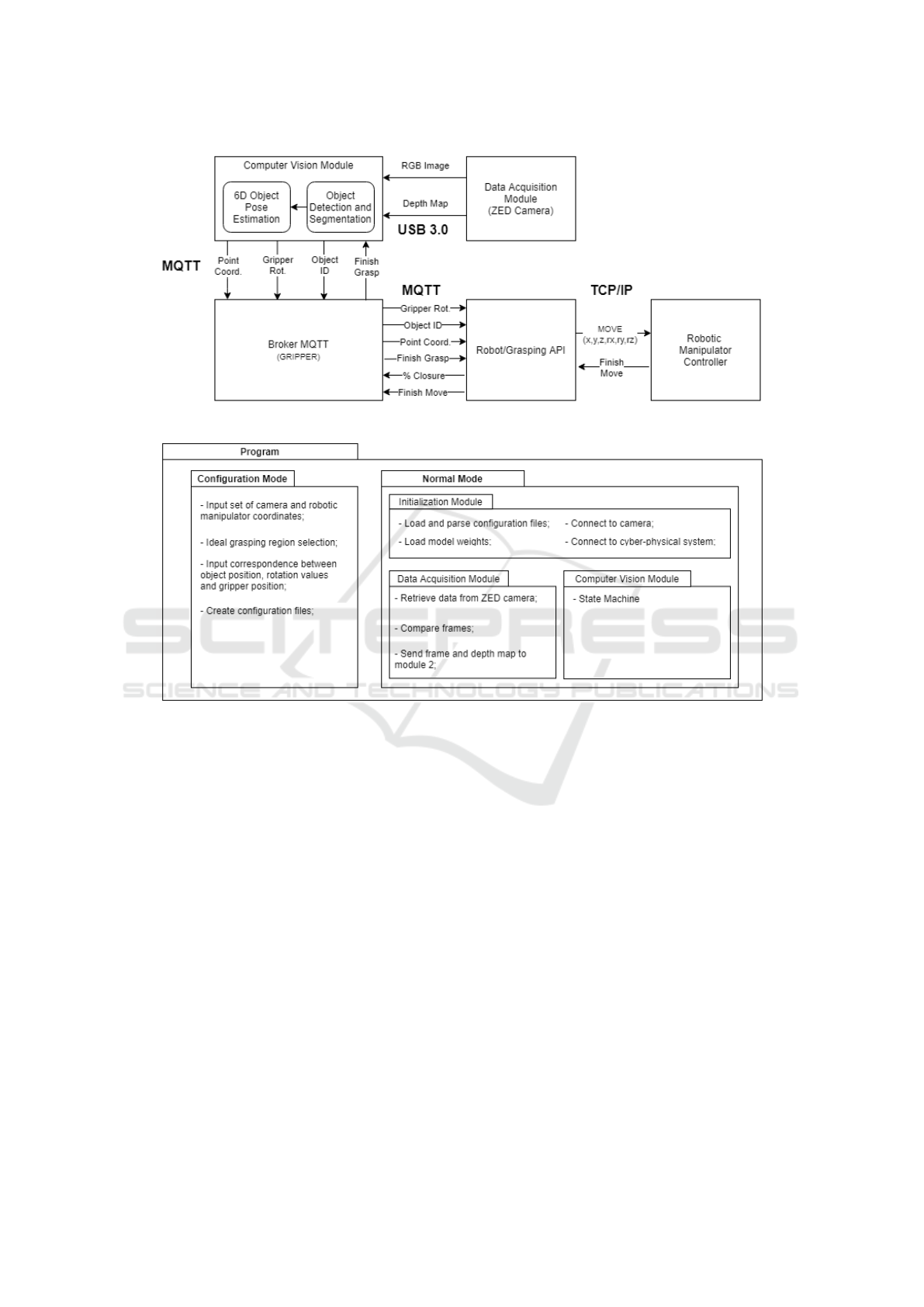
Figure 1: General system architecture with data flow illustration.
Figure 2: Overview of all operation modes.
are ideal for grasping. This selection is essential, as
it provides the user with the possibility of adapting
the optimal grasping position according to the spe-
cific task being performed. The selected points are
then saved to the second configuration file.
Finally, in the third step, the module requests the
user to input the range of rotation values that corre-
sponds to a particular position of the object, accord-
ing to grasping preference and application (such as a
rotation of 90 degrees around the x-axis correspond-
ing to the laying-down position). Afterward, the user
can also input a set of gripper rotations that give the
optimal grasping for a specific object position. These
values are saved into the third configuration file.
3.1.2 Normal Mode
This mode represents the main operational mode for
the system. It is divided into three distinct units. The
first unit (Initialization Module) runs only on start-
up and loads the various configuration files and mod-
els needed while also establishing the MQTT connec-
tions required. The other two units run in parallel for
the duration of the program.
The Data Acquisition Model has two main func-
tions. The first function runs on an infinite loop and
deals with data retrieval from the ZED camera. The
other function calculates differences between consec-
utive frames using the Structural Similarity (SSIM)
algorithm. This algorithm outputs a value from 0 to 1
that indicates how similar two images are. The func-
tion compares this value to a threshold value to tell if
there were changes between frames (such as an object
moving). In the Computer Vision Module, a state ma-
chine (Figure 3) is implemented. There is one Initial
state and four main states:
• Detection: implements the Object Detection and
Segmentation system;
• Localization: implements the 6D Object Pose Es-
timation system;
• Ready to Grasp: chooses which object to grasp
Automatic 3D Object Recognition and Localization for Robotic Grasping
419
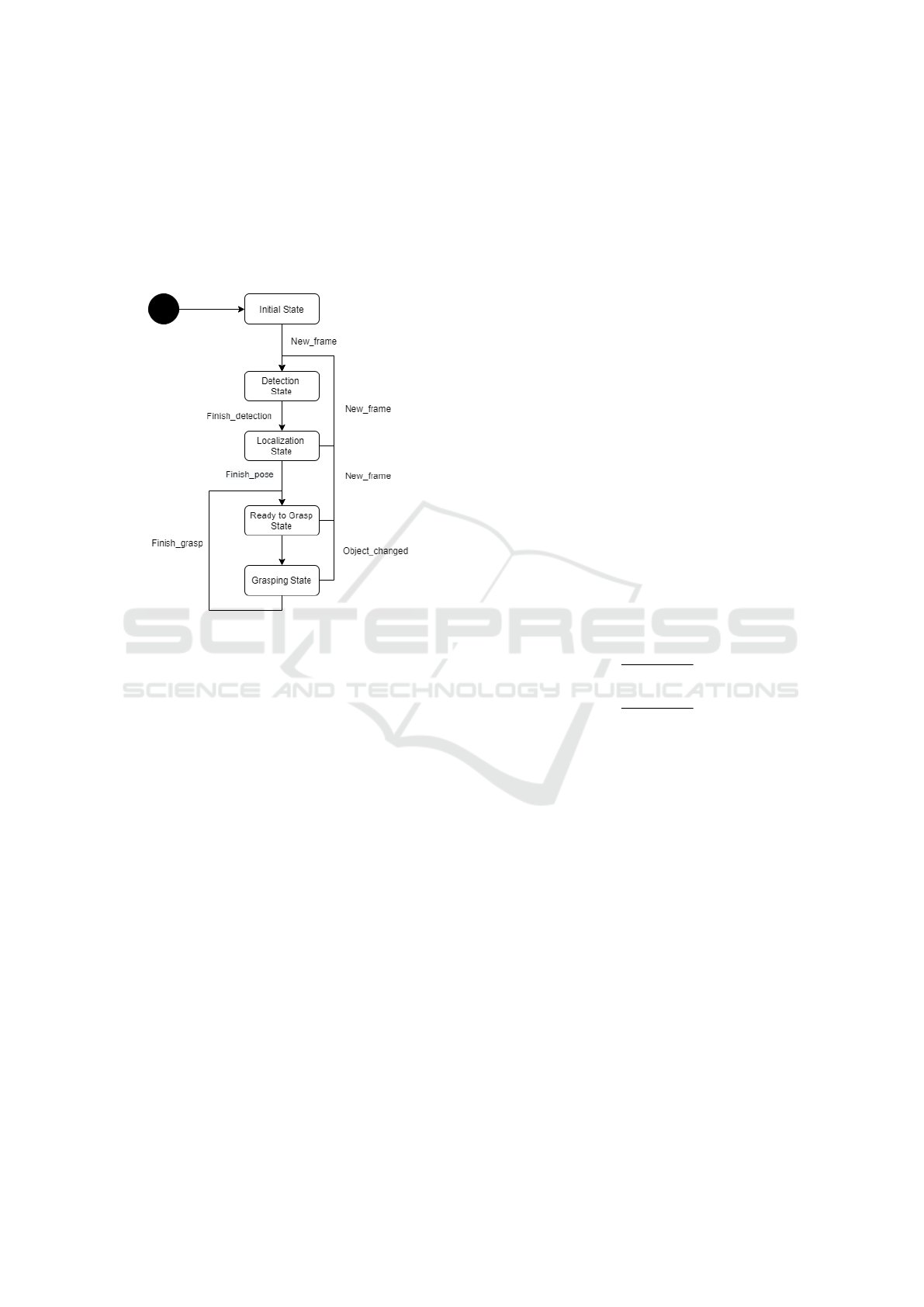
and sends coordinates to robotic manipulator;
• Grasping: waits for grasping to finish and tries to
detect changes in frame.
The transition between states depends on the changes
between frames that are detected in module 1. If any
object in the frame moves or disappears, the whole
state machine resets to the Detection state.
Figure 3: State machine of the pose estimation module.
4 DEEP LEARNING MODELS
4.1 Detection and Segmentation Model
The object detection and segmentation model is com-
posed of a pre-processing stage and an inference
stage. In pre-processing, the data received from the
Data Acquisition module is processed, so it can be fed
into the inference stage, which is made up of a Mask-
RCNN model(He et al., 2017). This stage then out-
puts a set of object identifications, bounding-boxes,
segmentation masks, and confidence values for each
object in the camera frame.
In the pre-processing stage, three RGB image
frames and corresponding depth maps are received by
the pipeline, and an average of the pixel values for
both the RGB frames and the depth maps are calcu-
lated. This is to help reduce the impact of small illu-
mination differences, pixel shifting, and random noise
when a frame is acquired, which in turn reduces the
flickering effect in the object masks.
Two different alternatives were analyzed for in-
ference: using YOLO with a segmentation mask
network overhead (much like how Mask-RCNN im-
proves upon Faster R-CNN) or using Mask-RCNN
instead. The conclusions were that Mask R-CNN
is actually more accurate and marginally faster than
the other alternative; therefore, it is actually a better
choice for this implementation.
4.2 Pose Estimation Model
This model begins with a pre-processing stage, which
processes the data received from the object detection
model to optimize the inputs of the pose estimation
stage. In pose estimation, a Densefusion(Wang et al.,
2019) architecture is used for inference, and it outputs
a set of rotation quaternions and translation vectors
for each object. A pose refinement stage is then ap-
plied to give a better pose estimation. Finally, a post-
processing stage is executed to calculate the final op-
timal grasping point coordinates and gripper pose for
every object in the frame.
In pre-processing, the mask obtained from Mask-
RCNN is used to obtain a set of object’s depth map
points. From this set, a group of 2000 points is sam-
pled at random in order to have a proper distribu-
tion throughout the whole object. The value of 2000
points, after some testing, was chosen because it is a
good trade-off between accuracy and speed. With the
points chosen, the point cloud x and y values for each
point is calculated, following Equations 1 and 2.
x =
(a − cx) × z
f x
(1)
y =
(b − cy) × z
f y
(2)
In these equations, z in calculated by dividing
depth by scale. Depth represents the depth value for
a point, scale depends on the measurement units used
by the camera, a and b are the pixel coordinates for a
point and cx, cy, fx and fy are intrinsic camera param-
eters. Following all this pre-processing, the Densefu-
sion model takes as input a crop of the camera image
frame (in the dimensions of the object’s bounding-
box), the calculated point cloud, the 2000 points from
the mask, and the object’s ID. The pose estimation
is outputted in the form of rotation quaternions and a
translation vector, which then goes through two itera-
tions of pose refinement, to produce better results.
The values obtained are used to create a transfor-
mation matrix that transforms the points in the ob-
ject 3D model from the canonical frame defined in
the dataset to the camera coordinate frame. In post-
processing, the set of optimal grasping points (which
were loaded from one of the configuration files), are
transformed according to the transformation given by
the Densefusion model. The center of this group of
ICINCO 2021 - 18th International Conference on Informatics in Control, Automation and Robotics
420

points is then calculated to give the optimal point of
contact for grasping.
5 EXPERIMENTS AND RESULTS
5.1 Dataset
In order to test and validate our proposed system, the
dataset used to train both the object detection and the
pose estimation models was the YCB-Video dataset,
which uses 20 objects from the YCB Object Model
Set (Calli et al., 2015). From a quantitative stand-
point, this dataset has 133827 RGB images (with
480x640 pixels) and their corresponding depth maps,
as well as a collection of the point cloud 3D models
of all the objects. The camera’s intrinsic parameters
and its positions in the world are also given for each
frame.
Figure 4: Distribution of number of instances per object.
In order to evaluate if the dataset was imbalanced,
the number of instances per type of object in the
dataset was plotted. As can be seen in Figure 4,
the distribution of instances for each object is rela-
tively balanced, and each object has at least 15000
instances. From a qualitative standpoint, the YCB-
Video dataset presents many advantages in terms of
variability: cluttered/uncluttered backgrounds, vary-
ing light conditions, and simple/complex objects.
5.2 Object Detection Model
The training of this model was heavily based on the
idea of transfer learning. This method consists of us-
ing pre-trained weights from a model - obtained on
one dataset - as a starting point for training on a differ-
ent dataset. This approach speeds up training time and
increases performance, but only when the pre-trained
model learned relevant general features on a balanced
dataset.
In our first approach, the pre-trained weights were
used for every branch, except the network heads; on
the second approach, the pre-trained weights were uti-
lized only for the backbone feature extraction net-
work, except for the final layers. The first approach
resulted in a 14% drop in mask generation accuracy
and a 5% drop in class label accuracy in relation to
the second approach. Although the first approach
only takes 33 hours to train compared to the 46 hours
of training in the second approach, the segmentation
masks’ accuracy is paramount, so this is an acceptable
trade-off between speed and accuracy.
Table 1: Comparison of original and fine-tuned hyper-
parameter values.
Hyper-parameter
Original
value
Fine-tuned
value
Number classes NA 21
Max gt instances 100 10
Detection min confidence 0.8 0.7
ROI minibatch size 512 128
RPN nms threshold 0.7 0.5
Learning rate 0.02 0.002
RPN class loss 1.0 1.0
RPN bbox loss 1.0 0.01
Mrcnn class loss 1.0 1.0
Mrcnn bbox loss 1.0 0.01
Mrcnn mask loss 1.0 10.0
Given that the original hyper-parameters of the
model were optimized for the COCO dataset, the
hyper-parameters of the object detection model were
tuned. For that, Tensorboard (a visualization and op-
timization tool for tuning parameters in Tensorflow)
was used. In Table 1, a comparison between the orig-
inal and the fine-tuned model parameters is shown.
Table 2: Results for bounding-box and segmentation mask
precision on all objects.
Class
name
Object ID
Bounding-box
AP
Segmentation
mask AP
Master chef can 1 31.7 37.3
Cracker box 2 32.3 36.9
Sugar box 3 31.3 37.1
Tomato soup can 4 32.0 37.0
Mustard bottle 5 31.5 36.5
Tuna fish can 6 28.9 35.8
Pudding box 7 31.9 37.1
Gelatin box 8 32.3 37.4
Potted meat can 9 29.6 35.9
Banana 10 32.2 37.1
Pitcher base 11 31.8 36.8
Bleach cleanser 12 30.7 36.0
Bowl 13 32.2 37.2
Mug 14 31.8 35.8
Power drill 15 29.5 36.8
Wood block 16 32.3 37.0
Scissors 17 28.6 35.6
Marker 18 29.1 36.1
Clamp 19 28.9 35.7
Foam brick 20 31.0 36.7
Automatic 3D Object Recognition and Localization for Robotic Grasping
421
The results in Table 2 show that the average
bounding-box and segmentation mask precision is
comparable to the baseline values obtained on the
COCO dataset in (He et al., 2017). These values pro-
duce accurate segmentation masks for most objects,
which was the intended result.
5.3 Pose Estimation Model
Since Densefusion was already trained on the YCB-
Video dataset, pre-trained weights and parameters
were readily available for the implementation de-
scribed in (Wang et al., 2019). Therefore, this model’s
training strategy was to validate it with the pre-trained
weights on the YCB-Video dataset. There was no
need for parameter optimization, as the parameters
discovered in (Wang et al., 2019) were already op-
timal. The results of validation are presented in Table
3, where ADD-S represents the average distance be-
tween every point in the ground-truth pose and the
estimated pose.
Table 3: Results of validation of the pose estimation model.
Class
name
Object ID ADD-S (%)
Master chef can 1 95.8
Cracker box 2 94.7
Sugar box 3 97.1
Tomato soup can 4 93.4
Mustard bottle 5 97.0
Tuna fish can 6 96.3
Pudding box 7 95.5
Gelatin box 8 98.0
Potted meat can 9 91.1
Banana 10 96.1
Pitcher base 11 96.9
Bleach cleanser 12 95.3
Bowl 13 86.1
Mug 14 96.7
Power drill 15 95.5
Wood block 16 89.2
Scissors 17 95.0
Marker 18 97.1
Clamp 19 70.7
Foam brick 20 91.8
The worst performing objects are the bowl, the
clamp, and the tuna fish can. This is due to the bowl
and the clamp being symmetrical objects, which in-
fluences pose estimation, since the same viewpoint
results in different poses, but also due to the fact that
they are texture-less objects, which makes it harder
for the network to extract feature keypoints from
them. The tuna fish can show poor results due to its
small size (for the same reasons that it had poor de-
tection results).
5.4 Computer Vision Module Testing
After training both models that compose the Com-
puter Vision Module individually on the YCB dataset,
the complete pipeline was analyzed. In this testing
phase, the localization model’s output was tested us-
ing as input the outputs given by the object detection
model. This is an important test to understand the im-
pact of detection errors on pose estimation.
One of the first issues encountered was loading
both model weights into the GPU at the same time.
Since model weights take up a lot of GPU mem-
ory, the pose estimation model would fail due to the
GPU running out of available memory during calcu-
lations. The solution to this problem was to load the
less computationally expensive model (object detec-
tion model) weights into CPU memory while keeping
the pose estimation model running on the GPU. The
results in Table 4 show the accuracy of the pose esti-
mations, following the same metric used in 3.
Table 4: Results of testing on the Computer Vision Module.
Class
name
Object ID ADD-S (%)
Master chef can 1 77.5
Cracker box 2 72.7
Sugar box 3 72.6
Tomato soup can 4 71.5
Mustard bottle 5 78.4
Tuna fish can 6 70.0
Pudding box 7 79.4
Gelatin box 8 80.3
Potted meat can 9 74.0
Banana 10 78.6
Pitcher base 11 77.2
Bleach cleanser 12 78.1
Bowl 13 69.8
Mug 14 80.6
Power drill 15 73.0
Wood block 16 70.2
Scissors 17 73.9
Marker 18 71.4
Clamp 19 56.5
Foam brick 20 68.8
The results in Table 4 drop close to 20 points in
accuracy, for almost every object, in relation to the
results presented in Table 3. This drop is an ex-
pected outcome since the original Densefusion model
uses exact segmentation masks from the ground-truth,
which gives an accurate region of points belonging to
ICINCO 2021 - 18th International Conference on Informatics in Control, Automation and Robotics
422

a given object. The object detection model, however,
has some errors in its segmentation masks. This er-
ror results in the segmentation mask covering parts
of different objects, especially when multiple objects
are close together, on one extreme, or not covering the
entire object, on the other.
6 LIVE SYSTEM VALIDATION
For validating the live system, some online tests were
made. A group of 6 objects was selected from the 20
in the dataset. It was important to choose two objects
with the worst performance in offline testing, as well
as two objects that were top-performers. This enables
the testing to validate if the patterns observed in the
simulation are reproduced in a real environment. Due
to the industrial context of the project, two tools were
also selected. The list of objects used is as follows: 1)
Bowl; 2) Clamp; 3) Gelatin box; 4) Marker; 5) Mug,
and 6) Power drill.
The test setting was an environment with con-
trolled lighting and a table where the objects would
be placed. A ZED camera was positioned in front of
the table and connected (via USB 3.0) to a computer
running the system and equipped with a GeForce RTX
2080 Ti GPU. A collaborative robotic arm with a 5kg
payload (Universal Robots’ UR5) with a 3D printed
gripper, was used for the grasping experiments. The
following tests were performed:
1. Testing the Data Acquisition Module (frame ac-
quisition and analysis);
2. Testing the Object Detection and Segmentation
model for identifying each object in various po-
sitions and visually validate the object’s produced
mask;
3. Testing the final Computer Vision Module output
(Identification + Pose) with a grasping experiment
and measuring the processing time of each com-
ponent;
The training dataset used for this model was a
smaller version with only 2000 instances per object.
This presents an exciting analysis opportunity on the
effects of using a smaller dataset with transfer learn-
ing.
6.1 Object Detection and Segmentation
Testing
In this test, the aim was to validate the object de-
tection and segmentation model and evaluate its per-
formance in a typical grasping setting. Several ob-
jects were arranged on the workspace (as can be seen
in Figure 5), and close to ten seconds of frames (at
15fps) were retrieved and analyzed by the Object De-
tection and Segmentation model. The results measure
the percentage of accurate, inaccurate, and no detec-
tions, as well as the model’s average confidence. The
reduced dataset has a big impact on detection perfor-
mance. The main issues with the use of so few in-
stances of each object results in the following prob-
lems:
• For complex objects (such as the clamp), the
model needs more data to be able to distinguish
features between objects, resulting in situations of
incorrect classification;
• Even for objects with simple features (like the
gelatin box, the bowl, and the marker), the model
overfitted to certain viewpoints (which were more
prevalent in the reduced dataset), which resulted
in no detection in certain object positions;
• When objects were too close together, the model
had trouble in correctly detecting them, since this
ability is a more complex feature that needed more
training data;
However, as in any other problem, besides the is-
sues, there are some positive aspects worth mention-
ing regarding the model’s performance:
• The model is able to generalize and correctly
identify objects which are different from the
dataset, even with limited data. This is the case
of the gelatin boxes, which have different height
and width in relation to the original object; the
bowl, which is taller and less wide than the orig-
inal model; and the mug, which has a different
color and is more narrow than the dataset model;
• With the limited amount of training data, the
model is still able to detect accurately and with
great confidence, the less complex objects, like
the gelatin boxes, the bowl, and the mug;
• Even with heavy occlusion (as seen in Figure 5f),
the model can correctly detect the bowl;
6.2 Grasping Experiments
In the final test, the computer vision module was val-
idated. The testing methodology used was a grasping
experiment on the 5 of the 6 objects that were cho-
sen for testing. This was due to the available gripper
being too small to be able to grasp the power drill.
Each object was placed in a different work-space
position, surrounded by other objects. A grasping at-
tempt was made for each position, for a total of five
attempts. Illustrations of one of the positions for each
object are presented in Figure 6. The results obtained
Automatic 3D Object Recognition and Localization for Robotic Grasping
423
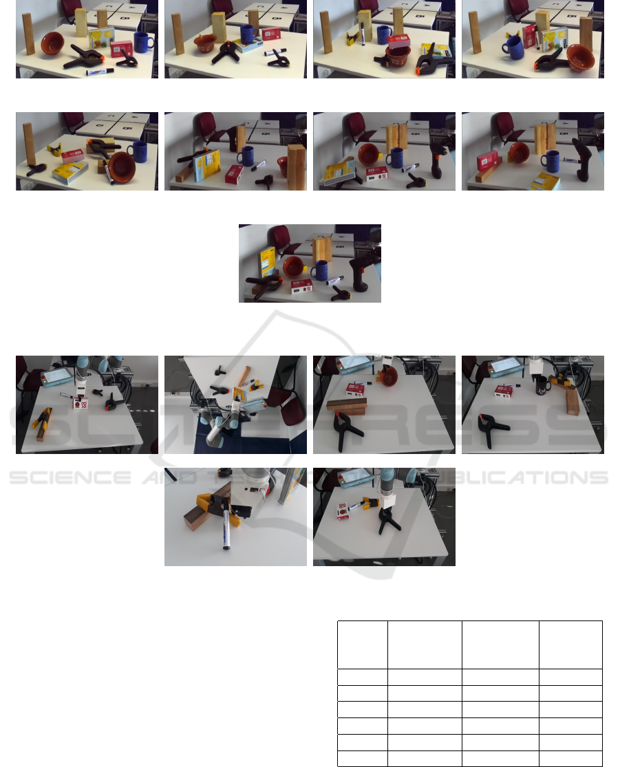
(a) Scene 1 (b) Scene 2 (c) Scene 3 (d) Scene 4
(e) Scene 5 (f) Scene 6 (g) Scene 7 (h) Scene 8
(i) Scene 9
Figure 5: Overview of all the scenarios used in detection testing.
Figure 6: Overview of all the grasping scenarios.
were recorded in Table 5. For each object, the Com-
puter Vision Module ran detection, generation of the
segmentation mask, and pose estimation. The center
point of the object’s coordinates were obtained, and
a transformation was applied from the center point to
the optimal grasping point to enable correct grasping.
Due to some time-restrictions, the set of opti-
mal grasping points’ transformation was not imple-
mented. However, this test serves as a proof of con-
cept, since the transformation of all object points is
equivalent to the transformation of the optimal grasp-
ing points. Furthermore, since the primary purpose of
this project is to develop a system for object recogni-
tion and localization, the main focus was on the cre-
ation of a pipeline with those capabilities.
Table 5: Grasping results.
Scene Object ID
Successful
attempts
(%)
Average
error
(cm)
1 8 60 2
2 8 60 5
3 13 20 2.7
4 14 80 0.5
5 18 60 3.5
6 19 40 0.75
7 CONCLUSIONS
In this paper, the problem of developing an automatic
object recognition and pose estimation system was
ICINCO 2021 - 18th International Conference on Informatics in Control, Automation and Robotics
424

addressed. This system combines object localization
and identification to improve robotic grasping. This
work’s main contribution was the development of a
framework integrating two different ML models to
create a system for more complete and autonomous
grasping tasks.
This paper’s main focus was on the integration of
two different ML models for detection and pose es-
timation. Both Mask-RCNN and Densefusion were
correctly integrated and show adequate results in
a real testing environment. The developed system
is capable of detecting movements and differences
between video frames, therefore reducing the need
for constant calculation and inference on each video
frame. The proposed solution runs entirely automat-
ically after an initial user parameters’ selection and
can generate grasping outputs from video data at a
rate of 2.6fps.
An interesting positive aspect of the proposed so-
lution is the ability of a human to be in control of
choosing the optimal grasping points for an object and
creating a configuration file with these points. This
allows for user and application adaptability while in-
creasing the system’s accuracy and speed since it does
not estimate these points during run time. The main
limitations found in the proposed solution were the
overhead work needed to output correct gripper rota-
tions for certain object positions, the impact of light-
ing conditions, and the dependency on previously
scanned 3D models of the actual objects.
ACKNOWLEDGEMENTS
INDTECH 4.0 – New technologies for intelligent
manufacturing. Support on behalf of IS for Techno-
logical Research and Development (SI
`
a Investigac¸
˜
ao
e Desenvolvimento Tecnol
´
ogico). POCI-01-0247-
FEDER-026653.
REFERENCES
Bicchi, A. and Kumar, V. (2000). Robotic grasping and
contact: a review. In Proceedings 2000 ICRA. Mil-
lennium Conference. IEEE International Conference
on Robotics and Automation. Symposia Proceedings
(Cat. No.00CH37065), pages 348–353 vol.1.
Calli, B., Walsman, A., Singh, A., Srinivasa, S., Abbeel, P.,
and Dollar, A. M. (2015). Benchmarking in manip-
ulation research: Using the yale-cmu-berkeley object
and model set. IEEE Robotics Automation Magazine,
22(3):36–52.
Dai, J., Li, Y., He, K., and Sun, J. (2016). R-FCN:
Object detection via region-based fully convolutional
networks. Advances in Neural Information Processing
Systems, pages 379–387.
Farhadi, A. and Redmon, J. (2018). Yolov3: An incremental
improvement. Computer Vision Pattern Recognition.
He, K., Gkioxari, G., Doll
´
ar, P., and Girshick, R. (2017).
Mask r-cnn.
Lenz, I., Lee, H., and Saxena, A. (2015). Deep learning for
detecting robotic grasps. The International Journal of
Robotics Research, 34(4-5):705–724.
Li, Y., Wang, G., Ji, X., Xiang, Y., and Fox, D. (2019).
Deepim: Deep iterative matching for 6d pose estima-
tion. International Journal of Computer Vision.
Liu, W., Anguelov, D., Erhan, D., Szegedy, C., Reed, S.,
Fu, C. Y., and Berg, A. C. (2016). SSD: Single shot
multibox detector. Lecture Notes in Computer Sci-
ence, 9905 LNCS:21–37.
Miller, A. T., Knoop, S., Christensen, H. I., and Allen,
P. K. (2003). Automatic grasp planning using shape
primitives. In 2003 IEEE International Conference
on Robotics and Automation, pages 1824–1829 vol.2.
Peng, S., Liu, Y., Huang, Q., Zhou, X., and Bao, H. (2019).
Pvnet: Pixel-wise voting network for 6dof pose es-
timation. 2019 IEEE/CVF Conference on Computer
Vision and Pattern Recognition (CVPR).
Redmon, J., Divvala, S., Girshick, R., and Farhadi, A.
(2016). You only look once: Unified, real-time object
detection. Proceedings of the IEEE Computer Society
Conference on Computer Vision and Pattern Recogni-
tion, 2016-Dec:779–788.
Redmon, J. and Farhadi, A. (2017). YOLO9000: Better,
faster, stronger. Proceedings - 30th IEEE Conference
on Computer Vision and Pattern Recognition, CVPR
2017, 2017-Jan:6517–6525.
Ren, S., He, K., Girshick, R., and Sun, J. (2017). Faster R-
CNN:Towards Real-Time Object Detection with Re-
gion Proposal Networks. IEEE Transactions on Pat-
tern Analysis and Machine Intelligence, 39(6):1137–
1149.
Rusinkiewicz, S. and Levoy, M. (2001). Efficient variants
of the icp algorithm. In Proceedings Third Interna-
tional Conference on 3-D Digital Imaging and Mod-
eling, pages 145–152.
Saxena, A., Driemeyer, J., and Ng, A. Y. (2008). Robotic
grasping of novel objects using vision. The Interna-
tional Journal of Robotics Research, 27(2):157–173.
Song, C., Song, J., and Huang, Q. (2020). Hybridpose: 6d
object pose estimation under hybrid representations.
Wang, C., Xu, D., Zhu, Y., Martin-Martin, R., Lu, C.,
Fei-Fei, L., and Savarese, S. (2019). Densefusion:
6d object pose estimation by iterative dense fusion.
IEEE/CVF Conference on Computer Vision and Pat-
tern Recognition.
Xiang, Y., Schmidt, T., Narayanan, V., and Fox, D. (2018).
PoseCNN: A Convolutional Neural Network for 6D
Object Pose Estimation in Cluttered Scenes.
Zakharov, S., Shugurov, I., and Ilic, S. (2019). DPOD: 6D
Pose Object Detector and Refiner.
Automatic 3D Object Recognition and Localization for Robotic Grasping
425
