
Characterization of a Vertical Submersible Six-stage Pump:
Accounting for the Induced Forces and Stresses
Patrick Zito Malonda
1
, Guyh Dituba Ngoma
1
, Walid Ghié
1
, Fouad Erchiqui
1
and Python Kabeya
2
1
University of Quebec in Abitibi-Témiscamingue, School of Engineering’s Department,
445, Boulevard de l’Université, Rouyn-Noranda, Quebec, J9X 5E4, Canada
2
University of Kinshasa, Department of Mechanical Engineering, Kinshasa, Democratic Republic of the Congo
Keywords: Vertical Submersible Multistage Pump, Axial and Radial Forces, Stress, Strain, CFX, Static Structural
Analysis.
Abstract: This study deals with the numerical investigation on the shaft behavior of a vertical submersible multistage
pump in terms of the axial and radial forces, and the stresses due to the liquid flow through the pump while
taking into account different conditions of operation, the gap between the impeller and the diffuser, the
rotating speed and the number of stages. This is to improve the pump performances while selecting the
bearings and/or the bushes of the submersible pumps in a suitable manner with a long operational life and
high reliability. From an existing vertical submersible six-stage pump, a pump model is developed. The
continuity, the Navier-Stokes, the stresses and the strains equations are applied to obtain by means of the
ANSYS-codes the fields of the liquid flow velocity and the pressure, the stresses, the strains, so as the axial
and radial forces. Numerical simulations are carried out to analyze the shaft behavior. The results obtained
for the pump head and the stress are validated using the experimental results of the pump head and the results
from the classical equations of stresses.
1 INTRODUCTION
The growth constantly of the number of deep mines
in construction and in exploitation in Canada leads
more and more to use very intense of the vertical
submersible multistage pumps with high pressure in
order to drain and to control the level of water in
mines. The considered vertical submersible six-
stage pump in this work is composed, inter alia, of a
vertical shaft, six impellers, six diffusers, a motor, a
suction body and a discharge body. The failing of a
pump in a mine can have a very ominous impact on
the environment. The security of the surrounding
work environment depends extensively on its
reliability, its good working and its life span. For the
constructors of the hydraulic pumps, the design, the
manufacture and the characterization of the vertical
submersible multistage pumps always present a big
challenge due to difficult to choose of the materials
of the pump components; the performances to reach
in terms of the pump head, the brake horsepower,
the axial and radial loads, the stresses and the
strains. A better manufacture of these pumps
requires a determination with precision of all key
parameters of its components while taking account,
in the design phase the axial and radial loads, the
strains and the stresses. Theoretical and
experimental several research works have been
achieved on the centrifugal pumps and the vertical
submersible multistage pumps in tie with the axial
and radial forces, the strains and the stresses on the
pump shaft (Karassik, 1998; Gülich, 2010; Karassik
et al., 2008; TM.P. S.p.A., 2003; Mohand-
Amokrane Abdelouahab et al., 2020; Bin, et al.,
2008; Zhou et al., 2014; Smith et al., 2005; Wang et
al., 2013; Wang et al., 2014; and Suke et al., 2015).
Indeed, in the books (Karassik, 1998; Gülich, 2010;
Karassik et al., 2008; and TM.P. S.p.A., 2003), the
authors presented theoretical and empiric
approaches to calculate, among others, the axial and
radial forces, the stresses and the strains on the
shafts of the centrifugal and submersible pumps. It
has been underlined that the developed relations are
dependent of the types of pump including the
measurements and the conditions of operations.
They cannot be automatically generalized to all
pumps. In the article (Mohand-Amokrane
Abdelouahab et al., 2020), the authors studied
92
Malonda, P., Dituba Ngoma, G., Ghié, W., Erchiqui, F. and Kabeya, P.
Characterization of a Vertical Submersible Six-stage Pump: Accounting for the Induced Forces and Stresses.
DOI: 10.5220/0010551100920101
In Proceedings of the 11th International Conference on Simulation and Modeling Methodologies, Technologies and Applications (SIMULTECH 2021), pages 92-101
ISBN: 978-989-758-528-9
Copyright
c
2021 by SCITEPRESS – Science and Technology Publications, Lda. All rights reserved
numerically the axial and radial forces, the stresses
and the strains on the shaft of a centrifugal four-
stage pump in some function of the type of diffuser
and the site of the diffuser to the last stage of pump.
It has been demonstrated that the diffuser has an
influence on the loads on the pump shaft. In the
article (Smith et al., 2005), the authors have
investigated on the vertical submersible turbine
pumps (9 and 31 stages) to determine the axial
forces, the stresses, the strains and the mechanical
vibrations on the pump shaft. The influencing
parameters on the loads have been identified. In the
article (Wang et al., 2013), the authors worked on
the optimization of the formula of calculation of the
axial force in vertical submersible multistage pumps
while taking into account the main liquid flows and
leak flow through the pumps. This approach
permitted to increase the precision in the
determination of the axial force. The numerical
results obtained have been compared with the
experimental results to the ends of validation. The
optimized formula gave some best results that the
traditional formula of the axial force. In the article
(Wang et al., 2014), the authors used the finite
element method to calculate the stresses and the
strains on the impellers of a vertical submersible
four-stage pump. The effect of the thickness of the
impeller blades on the stresses has been analyzed.
Of what precedes and while widening the review of
literature on the submersible pumps, it is to highlight
that there is not research focused on the submersible
pump that is considered in this research. In other
words, the effects of the axial and radial forces, the
strains and stresses on the performances of the
investigated submersible pump have not been
studied in the works of previous research. Failure to
account for (or the underestimation) these elements
in the design of the submersible can have negative
impacts on the size of the pump shaft and its
bearings (or the plain bearings) that are submitted to
variable axial and radial loads according to the
conditions of operation in terms of flow rates and
rotating speeds. Besides, in most previous research
works, the theoretical and empiric formulas to
calculate the axial and radial forces on the shaft of
pump have been elaborated in specific conditions in
terms of components, measurements and operation
of the pumps (Karassik, 1998; Gülich, 2010;
Karassik et al., 2008; TM.P. S.p.A. , 2003; Bin, et
al., 2008; Zhou et al., 2014; Smith et al., 2005; and
Wang et al., 2013). Considering the features of
different types of existing pumps, these formulas
cannot be applied automatically in the case of the
considered submersible pumps. Therefore, in this
study, it is about developing reliable and precise
numerical approach to determine the axial and radial
forces, the strains and the stresses in the vertical
submersible six-stage pump in while being based on
the existing submersible pump. The numerical
results achieved for the pump head and the stresses
are compared with the experimental results and the
results from classical equations of stresses.
2 MODEL DESCRIPTION
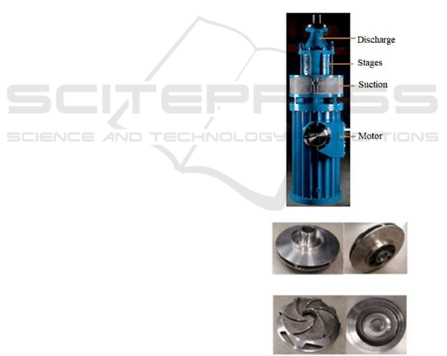
The vertical submersible six-stage pump considered
as the reference pump for this work is illustrated in
Fig. 1. It is composed, inter alia, of a shaft, six
impellers and six diffusers.
The solid and the fluid models of this pump are
shown in Fig. 2.
Impeller
Diffuser
Figure 1: Vertical submersible six-stage pump (Technosub
Inc., www.technosub.net).
Characterization of a Vertical Submersible Six-stage Pump: Accounting for the Induced Forces and Stresses
93
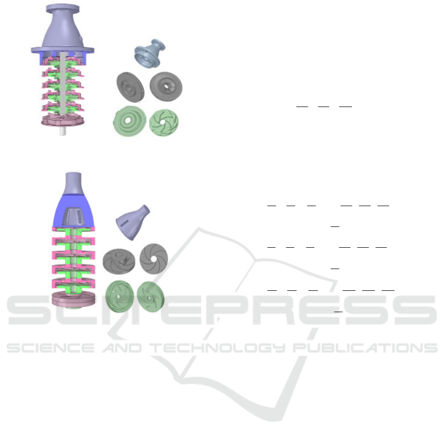
a) Solid model
b) Fluid model
Figure 2: Model of a vertical submersible six-stage pump.
3 MATHEMATICAL
FORMULATION
To determinate the field of the liquid flow velocity,
the field of the pressure, the stress and the strain in
a
vertical submersible multistage pump
, the following
hypotheses are considered for the liquid flow (
La
Roche-Carrier et al., 2013),
and the solid mechanics
(
Popov, 1999)
: (a) a steady state, three-dimensional
and turbulence flow using the k-
model is
assumed; (b) the liquid is an incompressible liquid;
(c) it is a Newtonian liquid; and (d) the liquid’s
thermophysical properties are constant with the
temperature; (e) the material is considered
continuous, doesn't have cracks, nor cavities; (f)
the material is homogeneous and presents the same
properties in all points; (g) the material is
considered as isotropic; and (h) no internal force
acts in the material before the application of the
external loads.
3.1 Liquid Flow Velocity and Pressure
The equations of the continuity and the Navier-Stokes
are used to obtain the fields of liquid flow velocity
and pressure. These equations are solved by means of
the ANSYS CFX-code (
ANSYS inc.). The equation of
the continuity is expressed as follows:
0
uvw
xyz
(1)
where u(x,y,z), v(x,y,z) and w(x,y,z) are the
components of the liquid flow velocity U(u,v,w).
Accounting for the gravity, the equations of the
Navier-Stokes can be formulated by:
222
222
2
222
222
( 2 )
eff
z
xz x
eff
uu u uuu
uvw
xy z
xyz
p
rvg
x
vv v vvv
uvw
xy z
xyz
2
222
222
( 2 )
z
yz y
eff
z
p
rug
y
ww w www
uvw
xy z
xyz
p
g
z
(2)
where g (g
x
,g
y
,g
z
) ist the gravity acceleration, p is the
pressure; is the density;
eff
is the effective viscosity
accounting for turbulence, it is defined as
.
eff t
is the dynamic viscosity and
t
is the turbulence
viscosity. It is linked to turbulence kinetic energy k
and dissipation ε
(
La Roche-Carrier et al., 2013).
3.2
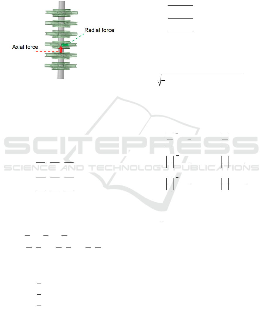
Axial and Radial Forces
Fig. 3 illustrates the axial and radial forces due to the
liquid flow through the vertical submersible six-stage
pump which is considered in this research. These
forces are determined using the ANSYS CFX-code.
The axial forces are the result of unbalanced impeller
forces acting in the shaft axial direction. Moreover,
the radial force on the impeller results from a non-
uniform distribution of pressure on the circumference
of the impeller. The non-uniform pressure
distribution can be caused by: the geometrical form
of the diffuser for the multistage centrifugal pumps;
the non-symmetrical impeller inflow; or the pump
operating regime. It is to highlight that the radial force
depends on the time. Its components are the static
radial force and the dynamic radial force. Generally,
the static radial force is greater than the dynamic
SIMULTECH 2021 - 11th International Conference on Simulation and Modeling Methodologies, Technologies and Applications
94
radial force (Abdelouahab, Mohand-Amokrane, et
al., 2020; Karassik, 1998; Gülich, 2010; Wang et al.,
2013; Watanabe, 2019; Gantar et al., 2002; Bolade et
al., 2015;TM.P. S.p.A. Termomeccanica Pompe,
2003; Karassik et al., 2008; Jino, T., 1980).
Figure 3: Axial and radial force in a model of the vertical
submersible six-stage pump.
3.3
Stresses and Strains
The normal and the shear
stresses on the pump shaft
are determinated by means of the equilibrium
equations of elasticity in terms of stress
n
eglecting the forces per unit of volume
(
Popov,
1999
)
. These equations are given by:
0
0
0
yx
xzx
xy y zy
yz
xz
z
xyz
xyz
xyz
(3)
The normal and the shear strains are formulated as
follows using the displacements (u,v,w) respectively
in the directions of x, y and z
; ;
; ;
xyz
xy yz zx
uvw
xzz
uv wv uw
y
xyzzx
(4)
Furthermore, the relationships between the stresses
and the strains is given by:
1
()
1
()
1
()
; ;
xxyz
yyzx
zzxy
xy yz
z
x
xy yz zx
E
E
E
GGG
(5)
where E is the modulus of elasticity, G is the shear
modulus and is the Poisson’s ratio.
In addition, the stresses can be written as the
function of the strains by:
(1 ) ( )
(1 )(1 2 )
(1 ) ( )
(1 )(1 2 )
(1 ) ( )
(1 )(1 2 )
; ;
xxyz
yyzx
zzxy
xy xy yz yz zx zx
E
E
E
GGG
(6)
The stress of von Mises selected for the yield criteria
can be expressed by:
22
2
12 23 31
1
2
(7)
where
1
,
2
and
3
, are the principal stresses in the
directions of 1, 2 and 3 according to
1
>
2
>
3
.
These stresses can be determined as follows (Popov,
1999):
1
1.5
2
22
10 3
1
1.5
2
22
20 3
1
2
22
30 3
1
2 cos arccos 0.5
33 3
1
2 cos arccos 0.5
33 3 3
1
2 cos arccos 0.5
33 3
JJ
J
JJ
J
JJ
J
1.5
3
(8)
Where
0
222
2
222
3
000
1
3
; ;
xyz
x y y z z x xy yz zx
x y z x yz y zx z xy
xx yy zz
Jssssss
Jssssss
sss
(9)
3.4 Diffuser Equations
The diffuser equations (Gülich, J. F., 2010) are used
in this research to calculate the main parameter of the
diffusers of the vertical submersible six-stage pump
as illustrated in Fig. 4.
Characterization of a Vertical Submersible Six-stage Pump: Accounting for the Induced Forces and Stresses
95
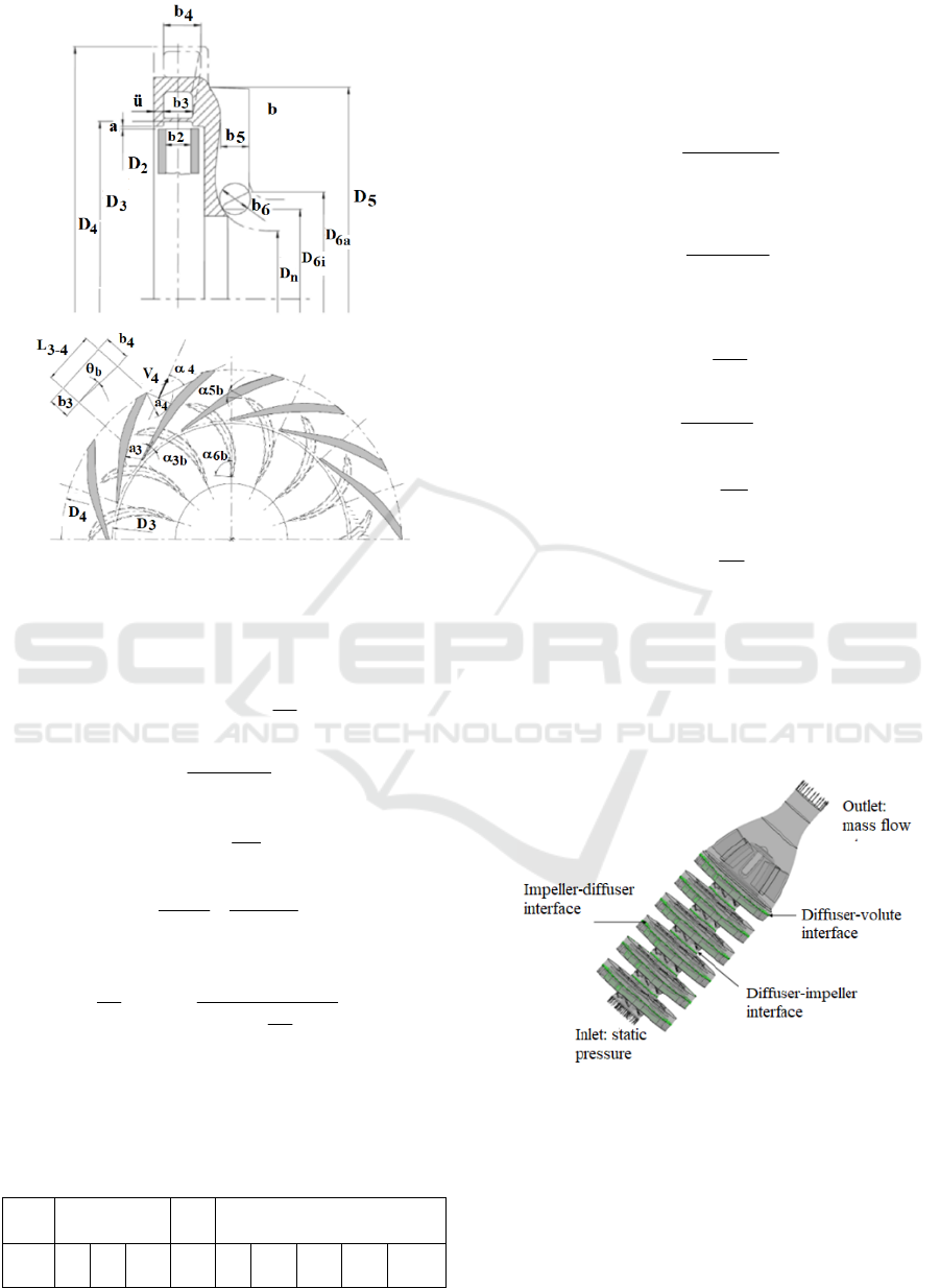
Figure 4: Diffuser parameters (Gülich, J. F., 2010 ).
These equations can be formulated as follows:
23
b1.3 to1.05b
(10)
1
3
33 3
3
3 and tan
m
b
u
V
V
(11)
33
3
3m
bD
Q
V
(12)
3
2
2u3u
D
D
VV
(13)
2
u1m1
2h
2
u
U
VU
U
gH
V
(14)
1
Z
2
D
Vb
Q
exp
2
D
fa
Le
2
u23
3
3a3
(15)
where 1.1 f
a3
1.3, the vane number of the diffuser
Z
Le
is chosen according to Tab. 1.
Table 1: Number of blades required for the diffuser (Gülich,
J. F., 2010 ).
Z
b
5 6 7
Z
Le
7 8 12 10 9 10 11 12 (15)
23
D015.0à01.0e
(16)
2q4
Dn01.015.1à05.1D
(17)
where n
q
is the specific speed.
43
34
1
b
L
aa5.0
tan
(18)
43b34
Ltanbb
(19)
6m6
65
VD
Q
bb
(20)
1m6m
V9.0à85.0V
(21)
5u
5m
1
5
V
V
tan
(22)
55
5
m
bD
Q
V
(23)
5
4
4u5u
D
D
VV
(24)
4
3
3u4u
D
D
VV
(25)
5
6
b
6
(26)
Moreover, Fig. 5 indicates the boundary conditions
used in this work. Indeed, at the pump inlet, the static
pressure is specified, while the flow rate is given at
the pump outlet. For the interaction of the impeller-
diffuser, the frozen rotor condition is applied.
Figure 5: Boundary conditions for the vertical submersible
six-stage pump.
4 RESULTS AND DISCUSSION
To study the shaft behavior in terms of the axial and
radial forces, and the stresses, three key parameters
were selected: (a) the intensity of the impeller
SIMULTECH 2021 - 11th International Conference on Simulation and Modeling Methodologies, Technologies and Applications
96
trimming (100 %, 91.7%, and 84.65 %); (b) the
number of the stages (4, 5 and 6 stages); and (c) the
shaft rotating speed (1800 rpm and 3600 rpm).
According the numerical results obtained, different
numbers of mesh elements are used in each case study
to achieve the mesh-independent solution tests. The
reference data applied for the shaft, the impeller, and
the diffuser are given in Tabs. 2-5.
Table 2: Pump shaft data.
Length L [mm] 655,15
Diameter d [mm] 45,06
Table 3: Impeller data.
Inlet blade height b
1
[mm] 30.17
Outlet blade height b
2
[mm] 14.48
Hub diameter D
h1
[mm] 44,45
Inlet diameter D
h2
[mm] 107.95
Outlet diameter D
2
[mm] 241
Inlet blade angle β
b1
[°] 16
Outlet blade angle β
b2
[°] 27.5
Blade thickness e [mm] 3.17
Blade number Z
b
7
Table 4: Diffuser (front side) data.
Inlet blade height b
3
[mm] 17.46
Outlet blade height b
4
[mm] 40.64
Inlet diameter D
3
[mm] 243,84
Outlet diameter D
4
[mm] 311.15
Inlet blade angle α
3b
[°] 10
Blade thickness e
3
[mm] 3.175
Blade number Z
Le
8
Table 5: Diffuser (rear side) data.
Return vane number Z
R
6
Outlet return vane height b
5
[mm]
24,4
Diameter at the inlet of the return
vane D
3
[mm]
311,15
Blade angle at the inlet of the
return vane α
5
[°]
95
Blade angle at the outlet of the
return vane α
6
[°]
18
Blade thickness of the return vane
e
3
[mm]
6,04
In addition, the properties of the 17-4PH steel and
the water considered are continued in Tabs. 6
and 7.
Table 6: Properties of the 17-4PH steel.
Module of the Young [Pa] 1,96x10
11
Poisson ratio 0,3
Compressibility module [Pa] 1,63x10
11
Shear module [Pa] 7,53x10
10
Resistance coefficient [Pa] 9,2x10
8
Ductility coefficient [Pa] 10
9
Yield strength [Pa] 7.93x10
8
Ultimate tensile strength [Pa] 1.103x10
9
Density [kg/m
3
] 7750,4
Table 7: Properties of water in 25 °C.
Density
[kg/m
3
]
Thermal
expansion
coefficient [K
-1
]
Kinematic
viscosity
[m
2
/s]
997 2,57x10
-1
0,884x10
-6
4.1 Case Study
4.1.1 Effect of the Impeller Trimming
To examine the effect of the variation of the impeller
diameter on the performances of the vertical
submersible six-stage pump, three impeller diameter
ratios of the 100 % (corresponding to the reference
impeller diameter: 241 mm), 91.7 % and 84.65 %
were selected when keeping other parameters
constant. Fig. 6 shows the pump head as a function of
the flow rate. From this figure, it can be seen that the
pump head decreases with the reduction of the
impeller diameter ratio. This can be explained by the
fact that the pressure difference between the impeller
outlet and inlet decreases with decreasing impeller
diameter ratio maintaining the diffuser inner diameter
constant. The energy of the fluid generated by the
rotating impeller was affected by the impeller
trimming which modifies the blade angle. In
addition, Fig. 7 indicates that the brake horsepower
diminishes with the reduction of the impeller
diameter ratio due to the requested diminution
impeller shaft torque relative to the size of the
impeller diameter keeping the diffuser inner diameter
constant. Furthermore, the corresponding efficiency
curves as a function of the flow rate illustrated in Fig.
8 shows that the efficiency is the best for the lowest
impeller trimming. Moreover, Figs. 9-11 show that
the impeller trimming decrease the axial force, the
radial force and the stress on the pump shaft. It may
be due to the interaction between the impeller and the
diffuser, that is reduced by the decrease of the
impeller diameter.
Characterization of a Vertical Submersible Six-stage Pump: Accounting for the Induced Forces and Stresses
97
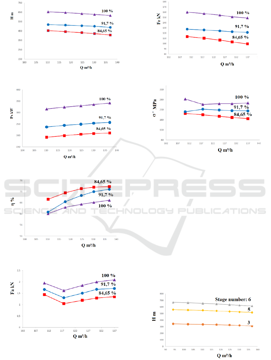
Figure 6: Head versus flow rate.
Figure 7: Brake horsepower versus flow rate.
Figure 8: Efficiency versus flow rate.
Figure 9: Axial force versus flow rate.
Figure 10: Radial force versus flow rate.
Figure 11: Stress versus flow rate.
4.1.2 Effect of Number of the Stages
To examine the effect of the stage number on the
pump shaft behavior, three pumps with 3, 5 and 6
stages are selected. Figs. 12-17 provide some
relevant information on the influence of the number
of the pump stages on the pump performances, the
axial and radial forces, and the stress. More the
number of the stages is raised, more the pump head is
important as shown in the Fig. 12. The brake
horsepower increases with decreasing the number of
the pump stages as indicated in Fig. 13, whereas the
efficiency is unchanged despite the number of the
pump stages as shown in Fig. 14. In addition, It can
see in Figs. 15-17 that the axial and radial forces, and
the stress diminish with decreasing the number of the
pump stages.
Figure 12: Head versus flow rate.
SIMULTECH 2021 - 11th International Conference on Simulation and Modeling Methodologies, Technologies and Applications
98
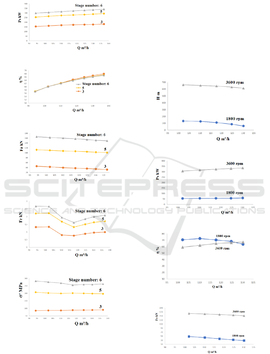
Figure 13: Brake horsepower versus flow rate.
Figure 14: Efficiency versus flow rate.
Figure 15: Axial force versus flow rate.
Figure 16: Radial force versus flow rate.
Figure 17: Stress versus flow rate.
4.1.3 Effect of the Shaft Rotating Speed
This analysis concentrates on the effects of the shaft
rotation speed on the performances of the vertical
submersible six-stage pump accounting for the
induced forces and the stresses on the shaft. Selecting
the rotating speeds of 1800 rpm and 3600 rpm, Figs.
18-23 show that the pump head and the brake
horsepower grow with increasing the rotation speed,
whereas the efficiency increase and decreases with
the rotation speed in the considered flow rate range.
Moreover, Fig. 21 and 22 indicate that respectively
the axial and radial forces increase with the
augmentation of the rotating speed. In regard to the
stress on the pump shaft, it raises with the growing of
the rotating speed as depicted in Fig. 23.
Figure 18: Head versus flow rate.
Figure 19: Brake horsepower versus flow rate.
Figure 20: Efficiency versus flow rate.
Figure 21: Axial force versus flow rate.
Characterization of a Vertical Submersible Six-stage Pump: Accounting for the Induced Forces and Stresses
99
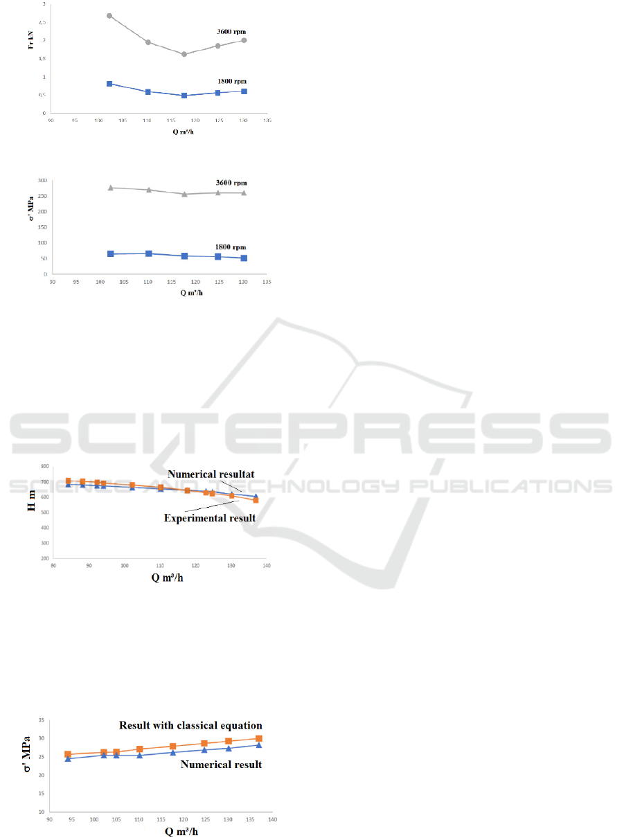
Figure 22: Radial force versus flow rate.
Figure 23: Stress versus flow rate.
4.2 Comparison of the Results
The numerical results of the head for a vertical
submersible six-stage pump are compared with the
experimental results to validate the developed
approach as depicted in Fig. 24. A good
agreement was observed between both curves.
Figure 24: Head versus flow rate.
In addition, the stresses obtained on the pump shaft
(one-stage pump) using the numerical simulations
and the classical equations are confronted as
illustrated in Fig. 25. This comparison shows good
harmony.
Figure 25: Stress versus flow rate.
5 CONCLUSION
In this work, the pump shaft behavior of a vertical
submersible multistage pump was numerically investigated
in terms of the axial and radial forces, and the stresses due
to the liquid flow through the pump while taking into
account different conditions of flow operation. The effects
of three key parameters such as the impeller trimming, the
rotating speed and the number of stages on the pump
performances were analyzed by means of the ANSYS-
codes. The simulation results achieved reveal, inter alia, the
existence of strong relationships between the pump
performances, the axial and radial loads, and the stresses on
the shaft varying the number of stages, the rotating speed
and the intensity of the impeller trimming. This could be
considered to improve the pump performances while
selecting the bearings and/or the bushes of the vertical
submersible six-stage pumps in a suitable manner with a
long operational life and high reliability. Finally, the
obtained numerical results for the pump head and the
stresses on the shaft are compared respectively with the
experimental results and the results using the classical
equations of stresses.
ACKNOWLEDGMENTS
The authors are grateful to the Technosub Inc.,
Industrial pumps manufacturing and distribution
(Rouyn-Noranda, Quebec, Canada).
REFERECES
Karassik, I. J., McGuire, T., 1998. Centrifugal Pumps.
Springer-Verlag US.
Gülich, J. F., 2010. Centrifugal Pumps, second Edition,
Springer.
Karassik, I. J., Messina, J. P., Cooper, P., Heald, C. C.,
2008. Pump Handbook. Fourth edition McGRAW-
HILL.
TM.P. S.p.A. Termomeccanica Pompe, 2003.
TERMOMECCANICA Centrifugal pump handbook,
La Spezia – Italy.
Abdelouahab, M. A., Guyh Dituba Ngoma. G., Erchiqui, F.,
Kabeya, P.(2020), Numerical Study of the Axial and
Radial Forces, the Stresses and the Strains in a High
Pressure Multistage Centrifugal Pump. 10th
International Conference on Simulation and Modeling
Methodologies, Technologies and Applications
(SIMULTECH). Online streaming, 8-10 juillet.
Xia, B., Kong, F., Zhang, H., Yang, L., and Qian, W., 2018.
Investigation of axial thrust deviation between the
theory and experiment for high-speed mine submersible
pump. Advances in Mechanical Engineering, Vol.
10(8) 1–13.
Zhou L., Shi W.D., Bai L., Lu W.G. and Li W., 2014
Numerical calculation and experimental study of axial
SIMULTECH 2021 - 11th International Conference on Simulation and Modeling Methodologies, Technologies and Applications
100

force in a deep-well centrifugal pump. Lat. Am. appl.
res. vol.44 no.1, Bahía Blanca ene.
Smith, D. R.; Price, S., 2005. Upthrust Problems On
Multistage Vertical Turbine Pumps. Turbomachinery
and Pump Symposia.
Wang C., Shi, W. and Zhang, L., 2013. Calculation
Formula Optimization and Effect of Ring Clearance on
Axial Force of Multistage Pump. Hindawi Publishing
Corporation, Mathematical Problems in Engineering,
Vol. 2013, Article ID 749375.
Wang, C., Shi, W., Si, Q., Zhou, L., 2014. Numerical
calculation and finite element calculation on impeller of
stainless steel multistage centrifugal pump. Journal of
Vibroengineering, Vol. 16, Issue 4, p. 1723-1734.
Suke, A. C., Londhe, B. P., Verma, A. B., 2015. Shaft
deflection Analysis of Multistage centrifugal Pump by
Finite element Method. International Journal of
Science, Engineering and Technology Research, Vol. 4,
Issue 7.
Technosub Inc., www.technosub.net.
Bolleter, U., Frei, A., 1993. Shaft Sizing for Multistage
Pumps. Turbomachinery Laboratories, Department of
Mechanical Engineering, Proceedings of the tenth
international pump users symposium.
Popov E. P., 1999. Engineering Mechanics of Solids, 2nd
edition, Prentice Hall.
La Roche-Carrier N., Dituba Ngoma G., and Ghie W.,
2013. Numerical investigation of a first stage of a
multistage centrifugal pump: impeller, diffuser with
return vanes, and casing. ISRN Mechanical
Engineering, Vol. 2013, Article ID 578072, 15 pages.
Gantar M., Florjancic D., and Sirok B., 2002. Hydraulic
Axial Thrust in Multistage Pumps - Origins and
Solutions. Journal Fluids Engineering, Vol. 124, Issue
2, 336-341, 6 pages.
Bolade, P. S., Madki, S. J., 2015. Analysis of Hydraulic
Thrusts in Centrifugal Pump to Increase the Bearing
Life. International Journal of Engineering Research &
Technology. ISSN: 2278-0181, Vol. 4 Issue 08.
Jino, T., 1980. Hydraulic axial thrust in multistage
centrifugal pumps. Journal of Fluids Engineering,
Volume 102, Issue 1, 6 pages.
Karassik, I. J., Messina, J. P., Cooper, P., Heald, C. C.,
2008. Pump Handbook. Fourth edition McGRAW-
HILL.
ANSYS inc., www.ansys.com.
Characterization of a Vertical Submersible Six-stage Pump: Accounting for the Induced Forces and Stresses
101
