
Real-time Robust Trajectory Control for Vehicle Platoons: A Linear
Matrix Inequality-based Approach
Alessandro Bozzi
a
, Enrico Zero
b
, Roberto Sacile
c
and Chiara Bersani
d
DIBRIS – Department of Informatics, Bioengineering, Robotics and Systems Engineering,
University of Genova, Genova, Italy
Keywords:
Robust Control, Trajectory Planning, Linear Matrix Inequality, Vehicle Platooning.
Abstract:
This paper proposes a solution to dynamically adjust vehicle platoon trajectories. The goal of the control
algorithm is to keep the optimal interdistance between adjacent vehicles proceeding at cruising speed on a
straight road. After a proposal of the interdistance required between neighboring vehicles, a robust decentral-
ized controller based on a linear control law provides the speed profile for each component of the platoon.
Its objective is to minimize the divergence in space in respect to the planned trajectories while assuring a safe
span between adjacent members of the platoon. The results on a limited instance demonstrate the effectiveness
of the proposed approach.
1 INTRODUCTION
Autonomous vehicles represent a topic of growing in-
terest in systems engineering. The goal to design un-
manned cars and to introduce them in the common
traffic is one of the most ambitious projects in the
current century, studied all over the world. Since
the road is a complex environment, many parame-
ters have to be taken into account for the car’s au-
tonomous motion. Firstly, smart sensors, located on
the vehicles or on the infrastructures, have to acquire
specific data such as videos and images from the sur-
roundings in order to identify the elements useful to
manage the vehicle tracking. Other devices have to
be installed to transmit the information, in real time,
to the control center which analyses and evaluates the
data and sends the correct control commands to the
vehicles. Some vehicles can send or receive automat-
ically the information about their states from or to-
ward a centralized decision maker in order to manage
their own trajectory according to the reconstructed en-
vironment. When the surrounding is virtually rebuilt,
the automated system can provide its control law by
modifying the acceleration, the speed and/or the steer-
ing of the vehicle replacing the human intervention.
Control techniques can also be applied to vehicle pla-
a
https://orcid.org/0000-0002-2436-0946
b
https://orcid.org/0000-0002-9995-1724
c
https://orcid.org/0000-0003-4086-8747
d
https://orcid.org/0000-0002-5779-9605
tooning, which refers to a set of cooperative auto-
mated vehicles which travel on the same trajectory in
a string formation.
There are already several findings that show how
autonomous driving could improve the throughput of
the road, while reducing the fuel emissions, especially
for platooning (Alam et al., 2014). While dealing with
platoon, many factors have to be considered. In this
case, in fact, each vehicle does not only follow its
path, but also it interacts with the other members of
the platoon. The involved vehicles retrieve informa-
tion on the surroundings and have to proceed harmo-
niously with the rest of the system. The interdistance
between adjacent vehicles has to be constantly moni-
tored by means of safety zones, designed accordingly
to road traffic rules and following principles intro-
duced in (Chen and Wang, 2007) and (Bersani et al.,
2015). The classification of safer or less safe areas
leads the choice of the trajectory generator algorithm
to be used.
In literature, many works tackle the trajectory
planning problem for one vehicle. In (Alia et al.,
2015), the authors used clothoid tentacles and occu-
pancy grid to generate a feasible path for a vehicle
and even allowing it to avoid obstacles. To achieve
the same objective, in (Choi et al., 2008), the Bezier’s
curve method is adopted. However, the definition of
the trajectory for a vehicle included in a platoon ap-
pears more complex.
410
Bozzi, A., Zero, E., Sacile, R. and Bersani, C.
Real-time Robust Trajectory Control for Vehicle Platoons: A Linear Matrix Inequality-based Approach.
DOI: 10.5220/0010550704100415
In Proceedings of the 18th International Conference on Informatics in Control, Automation and Robotics (ICINCO 2021), pages 410-415
ISBN: 978-989-758-522-7
Copyright
c
2021 by SCITEPRESS – Science and Technology Publications, Lda. All rights reserved

In particular, unpredictable events during the tran-
sit due to external factors may cause vehicle ap-
proaching or detachment from the other members of
the platoon. In this case, a control system which gen-
erates countermeasures, for each element of the sys-
tem, to restore the correct position, speed and inter-
distance has to be introduced in order to guarantee
passengers’ safety. The approaches may be central-
ized or decentralized. In the first case, usually the
leader regulates the vehicles’ position by providing
the optimal data for speed and acceleration to the fol-
lowers (Graffione et al., 2020b), while in the second
case, each member of the platoon uses as reference
the distance and the speed of the preceding vehicle
(Ghasemi et al., 2013).
In (Liu et al., 2019), the authors proposed an opti-
mal platoon trajectory control method by optimizing
accelerations of the vehicles in order to satisfy con-
straints related to travel delay and fuel consumption.
In (Huang et al., 2019), a distributed control model
is presented where each vehicle is independently con-
trolled by itself and it shares only information about
its motion state in order to perform vehicle merging or
splitting. The same problem has also been tackled in
(Graffione et al., 2020a) solved by a Model Predicted
Control model (MPC). In this latter case, the leader
coordinates the exchanged data with the vehicles in
order to perform the planned manoeuvres.
This paper presents a new algorithm to ensure the
correct maintenance of the distance between neigh-
boring vehicles, by means of a robust controller that
provide a linear control law. The offline procedure
should be activated when vehicles seem to have trou-
ble in keeping an optimal interdistance each other due
to external factors.
This work is organized as follows. Section 2 pro-
vides a deeper description of the safety zones clas-
sification and presents the proposed robust control
model. Section 3 shows a case study with simulation
and results, and finally Section 4 includes conclusions
and future developments.
2 MODEL AND METHOD
2.1 System Definition
The control of the platoon trajectory and the related
behaviour of the leader and the followers requires
an accurate model of the vehicles motion in order to
guarantee robustness and string stability.
To generate dynamically the set of trajectories, a
kinematic model of the vehicle has been used:
x
i
(t +1) = x
i
(t)+v
i
(t)∆t +w
i
(t) t = 0,..., T −1
(1)
where x
i
is the position of the i
th
vehicle, v
i
its veloc-
ity, w
i
the possible disturbance and ∆t the sampling
time. This simple approach ensures a fast modifica-
tion of the conditions and paired with limiters it can
provide the bounding of the input respecting physical
constraints.
In matrix form, the aforementioned system of M
vehicles may be formalized as follows:
x(t + 1) = Ax(t) + ∆tBv(t) + w(t) t = 0,..., T − 1
(2)
with A and B identical matrices ∈ R
M×M
.
In addition, it is assumed that each vehicle can
access to the information about its own position and
on both the preceding and the following vehicle posi-
tions. So:
y
i
= C
i
x
i
(3)
and for the generic i
th
vehicle:
C
i
=
0 ... 0 1 0 0 0 ... 0
0 ... 0 0 1 0 0 ... 0
0 ... 0 0 0 1 0 ... 0
(4)
where C
i
∈ R
3×M
.
The first and last vehicles of the platoon have
slightly different C
i
∈ R
2×M
matrix:
C
1
=
1 0 ... 0
0 1 ... 0
C
M
=
0 ... 1 0
0 ... 0 1
(5)
The specific structure of those matrices assures that
each vehicle monitors its own position and the posi-
tion of the vehicle which precedes and follows in the
string formation, as an example, by sensors such as
lidar and radar.
However, (Pates et al., 2017) and (Gao et al.,
2017) demonstrate that, to obtain better performances
of the control models regarding the scalability of the
system or in case of noisy measurements, it is recom-
mended to provide each vehicle also with information
coming from the leader’s position.
2.2 Safety Zones
In the management of the platoon trajectory, it is
significant to monitor the interdistance between each
couple of consecutive vehicles, in order to apply a
proper controller able to handle specific goals accord-
ing to the different situations during the driving ses-
sions. When two vehicles get closer, a safety as-
pect must be taken into account. In the proposed
approach, to classify critical situations, the interdis-
tance between two adjacent vehicles may be repre-
sented as three colored states, green (optimal), yellow
Real-time Robust Trajectory Control for Vehicle Platoons: A Linear Matrix Inequality-based Approach
411

Figure 1: Safety zones division.
(sub-optimal) and red (critical). When a vehicle is too
close to the adjacent one, its position may be repre-
sented by a red zone. The state of the vehicle turns in
yellow, whenever a safer-distance is re-established ac-
cording to a predefined threshold in space. The green
state represents a safe condition in respect to correct
interdistance among vehicles.
A schematic representation of safety zones is
shown in Fig.1 According to the state color, the ob-
jective of the control changes. The green zone is a
collision-free zone, in this case, the vehicle has to
keep a given speed, while maintaining the interdis-
tance. On the other hand, the red zone represents
collision-risk, as the distance with the preceding car
is not wide enough to guarantee safety. In this occur-
rence, the vehicle should perform a braking maneu-
ver and even stops itself in order to avoid a possible
collision, if for some external reason, the preceding
vehicle starts braking. The yellow intermediate zone
is by far the most interesting, since a vehicle must
pay attention to the preceding car because the inter-
distance is not small enough to induce an accident,
but not wide enough to allow a careless drive.
Hereinafter, the bounds of each zone are defined
as follows (distance in m, velocity in km/h):
d
red
≤
3 ×V
10
d
green
≥
V
10
2
d
red
< d
yellow
< d
green
(6)
given accordingly to the reaction and the braking time
of a human driver.
More in details, these bounds have been assigned
accordingly to the rules of the Italian road traffic,
which asserts as a recommended distance the sum of
the space traveled during the human reaction and the
braking time, while the minimum threshold is the re-
action space only. Nevertheless, these distances might
even be reduced, considering that autonomous ve-
hicles perform faster computation and input prompt
with respect to human being. In other words, the un-
manned vehicles’ reaction time is considerably lower.
Coherently with this reasoning, (Alam et al., 2014)
has shown that especially for heavy duty vehicles
(HDV) platooning the minimum distance to avoid col-
lision can be reduced.
However, in this paper it has been preferred to
maintain the canonical range. The proposed control
model will be applied considering the yellow inter-
mediate state of criticality.
2.3 Robust Control for Yellow Zone
The proposed robust control model deals with a situ-
ation in which vehicles are not optimally spaced (i.e.
they are in yellow zone) and while they are proceed-
ing with a given velocity. The behaviour in green and
red zone is assumed to be correctly performed by as-
signed controllers thus they are not considered in this
paper.
The robust controller’s purpose in the yellow zone
is to restore the desired interdistance minimizing the
speed variation, while keeping the planned trajectory,
despite disturbances that affect the system.
Thus, the trajectory of the i-th vehicle has to be
modified with respect to the desired reference path
a priori defined x
d
i
(t), leading to apply the following
change of variable:
(
˜x
i
(t) = x
i
(t) − x
d
i
(t)
˜v
i
(t) = v
i
(t) − v
d
i
(t)
(7)
The problem can be defined as minimax problem:
inf
v
sup
w6=0
J(v, w)
||w||
2
(8)
subject to (2) where the cost function J is designed as:
J(v,w) =
M
∑
i=1
T −1
∑
t=0
α
i
˜x
2
i
(t)+γ
i
˜v
2
i
(t)+
M
∑
i=2
T −1
∑
t=0
β
i
( ˜x
i
(t)− ˜x
i−1
(t))
2
(9)
In (9) α
i
,β
i
and γ
i
represent gains which give primary
importance respectively to tracking the trajectory,
restoring the optimal interdistance and minimizing
the difference from the desired velocity. The leader
vehicle is considered as an element of the platoon
(i.e. it is unmanned as the others) with the specific
feature that it does not have to care about keeping
some distance to a preceding vehicle.
Theorem 1. Let’s consider a time horizon of two in-
tervals, i.e. t = 0,...T and T = 1. The trajectory of
the platoon described by x(t) can be modified in real-
time, according to the problem defined by (8) and (2)
by an optimal control law v(t) = Kx(t), which is lin-
ear, where K is the solution of the following linear
matrix inequality (LMI):
min
θ,K
θ (10)
s.t.
K =
k
1,1
k
1,2
0 0 0 ... 0 0
0 0 k
2,1
k
2,2
k
2,3
... 0 0
0 0 0 0 0 ... 0 0
... ... ... ... ... ... ... ...
0 0 0 0 0 ... k
M,M−1
k
M,M
(11)
ICINCO 2021 - 18th International Conference on Informatics in Control, Automation and Robotics
412

ˆ
Q
xx
− θI +
ˆ
Q
xv
KC + C
T
K
T
ˆ
Q
vx
C
T
K
T
KC −
ˆ
Q
−1
vv
6 0
(12)
and θ > θ
?
:
inf
µ∈S
sup
06=x∈R
n
x
µ(Cx)
T
Q
x
µ(Cx)
!
/
kxk
2
= θ
?
(13)
Proof. From the cost function of (9) we can deduce
the matrix Q
J
for the minimax problem, so parti-
tioned:
Q
J
=
Q
xx
Q
xv
Q
vx
Q
vv
(14)
Q
xx
=
α
1
+ β
2
−β
2
... 0 0
−β
2
α
2
+ β
2
+ β
3
... 0 0
... ... ... ... ...
0 0 ... α
M−1
+ β
M−1
+ β
M
−β
M−1
0 0 ... −β
M−1
α
M
+ β
M
Q
vv
= diag(γ
1
,γ
2
,...γ
M
)
Q
xv
= Q
vx
= 0
(15)
Matrices thus obtained refer to a dynamic system. In
order to perform an offline computation of the trajec-
tory we need to transform the system from dynamic
to static. According to the available data on the state
and on the disturbance at initial time (i.e. x(0) and
w(0), hereinafter respectively x
0
and w
0
for sake of
notation) the following problem has to be solved:
inf
v
0
sup
x
0
,w
0
x
T
0
Q
xx
x
0
+ v
T
0
Q
vv
v
0
+ x
T
(1)Q
xx
x(1)
||x
0
,w
0
||
2
(16)
By writing x(1) as a function of x(0) from (2) and
developing the computation, (16) may be rewritten as:
inf
v
0
sup
x
0
,w
0
x
T
0
(Q
xx
+ A
T
Q
xx
A)x
0
+ v
T
0
(Q
vv
+ B
T
Q
vv
B) + x
T
0
A
T
Q
xx
Bv
0
+ v
T
0
B
T
Q
xx
Ax
0
||x(0),w(0)||
2
(17)
The numerator in (17) can be represented in the ma-
trix form as:
x
0
u
0
T
ˆ
Q
x
0
u
0
(18)
More in detail, the matrix
ˆ
Q is composed as follows:
ˆ
Q =
ˆ
Q
xx
ˆ
Q
xv
ˆ
Q
vx
ˆ
Q
vv
=
Q
xx
+ A
T
Q
xx
A A
T
Q
xx
B
B
T
Q
xx
A R + B
T
Q
vv
B
(19)
and it holds all the data needed to solve the LMI prob-
lem of Theorem 1.
Furthermore, Theorem 1 of (Gattami et al., 2012)
demonstrates that there exist linear decision µ
i
(C
i
x) =
K
i
C
i
x, for i = 1, ...,N where the finite value θ
∗
of the
game represented by equation (13) is achieved.
Corollary 1.1. The control can be applied on wider
time horizon, i.e. T > 1, applying results in (Gattami
and Bernhardsson, 2007), Section VII.
Table 1: Initial speeds.
Vehicle speed [m/s]
1 18.79
2 17.55
3 17.67
4 15.59
5 14.66
3 CASE STUDY
The case study refers to a five-vehicle platoon (M=5)
which is moving along a rectilinear path. A decreas-
ing in the speed profile of the vehicles which the pla-
toon consists of is considered.
The main goal of the control law is indeed to re-
store the correct distance, which is assumed to be at
least 29 meters according to (6) and provided that
platoon is willing to proceed at the cruising speed
of 15m/s, thus slightly reducing the velocity of the
first vehicles. In other words, the robust control aims
at spacing the vehicles with the correct interdistance
with smaller as possible variation of their speed.
Initial speeds used for our simulation are listed
in Table 1. This happens because they are not op-
timally spaced as between two neighboring vehicles
intervenes a distance of 20 meters (caused by exter-
nal factors prior to the start of the simulation), and
thus platoon is trying to actuate some techniques to
increase the span.
In this scenario the noise is assumed to be additive
white Gaussian, with zero mean and known covari-
ance.
Gains are maintained unitary for demonstration
purposes, but in a real implementation they need to
be tuned empirically according to their individual im-
portance. In particular, it is reasonable to prioritize
the restoring of the optimal interdistance when ve-
hicles seem to face difficulties in exiting the yellow
zone due to external factors. This will cause them to
significantly reduce their speed to obtain better stabil-
ity while resuming initial platoon shape.
Fig.2 shows the deviation of the vehicle position
with respect to the planned one. While in the very first
instants, a huge difference appears between desired
and actual trajectories, at the end of the simulation
which lasts 50 seconds, the convergence is achieved.
The results demonstrate the effectiveness of the robust
controller which restores the initial and optimal state
for the vehicles in the string formation.
Fig.3 displays the interdistance between vehicles
during the simulation. Also in this case, the prede-
fined values (29 meters) are recovered carrying out
the main objective of the control law.
Real-time Robust Trajectory Control for Vehicle Platoons: A Linear Matrix Inequality-based Approach
413
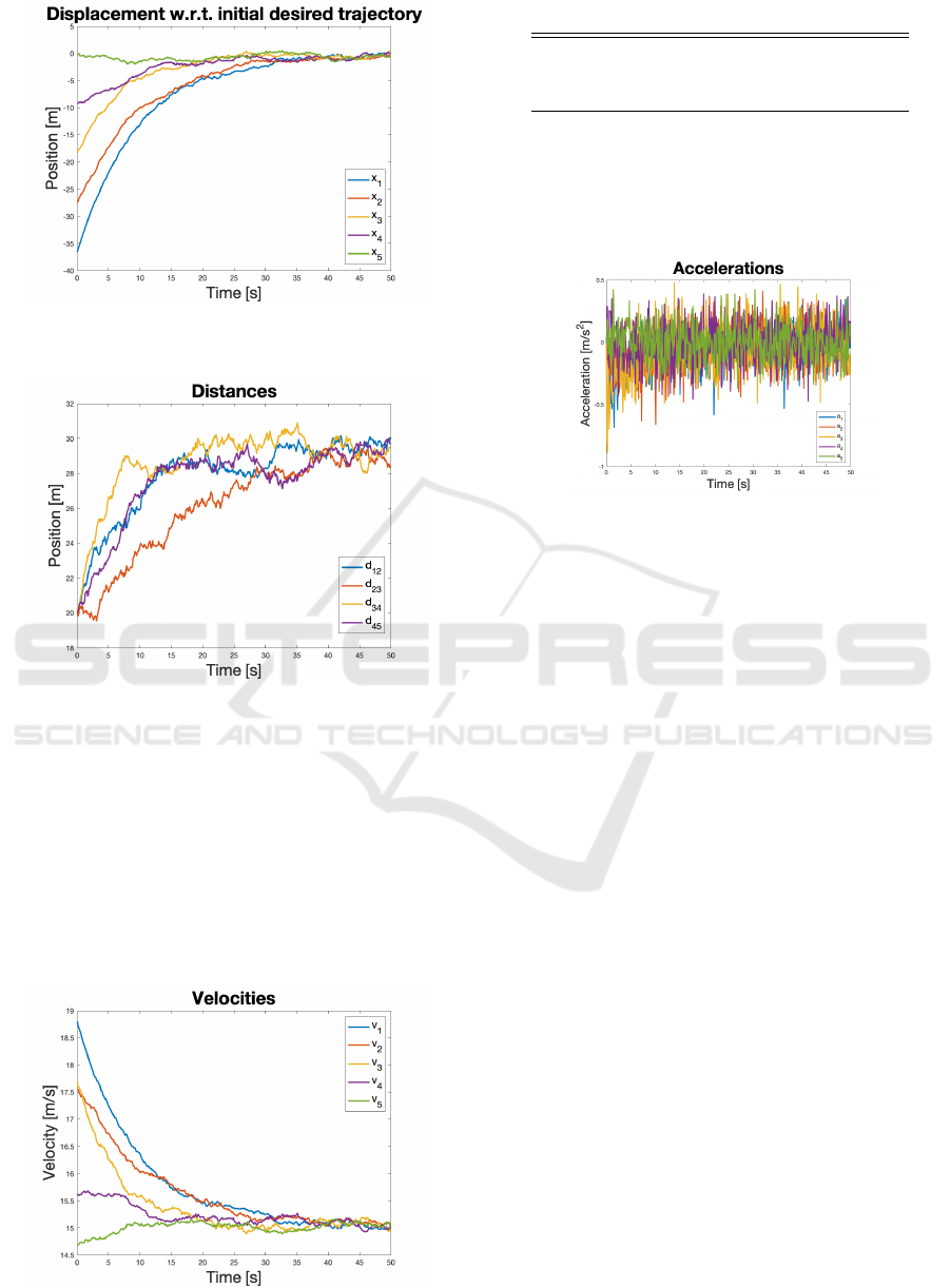
Figure 2: Divergence in vehicles’ position with respect to
the planned one.
Figure 3: Distance between neighboring vehicles.
Finally, Fig.4 displays the velocity trends, which
are coherent with the expectations: first vehicles need
to slow down to ensure a correct repositioning of the
other members of the platoon reaching out the sta-
bility after about 50 seconds. After that, they can
proceed at cruising speed and, in cooperative way,
increase both the speed and interdistance with other
control techniques.
Figure 4: Trend of the velocities.
Table 2: Vehicles’ state at the end of the simulation.
Vehicle Velocity [m/s] Distance from
preceding car
[m]
1 14.92 /
2 15.00 29.78
3 15.08 29.41
4 15.01 28.98
5 14.99 29.02
Figure 5: Vehicles’ accelerations.
Table 2 sums up vehicles’ velocity and distance
with the preceding element of the platoon, validating
our control algorithm.
4 CONCLUSION
In this paper, a robust control approach has been used
to restore the optimal interdistance between neighbor-
ing vehicles in a platoon trajectory planning.
The interdistance that can occur between two ad-
jacent vehicles has been classified in three different
levels according to growing safe conditions. The pro-
posed control model is dedicated to manage the ve-
hicle’s position and speed in the sub-optimal yellow
condition which is very sensitive in the design of ve-
hicle’s trajectory. Here, in fact, vehicles may assume
many different behavior, from the most aggressive to
the most conservative one.
The proposed control low restores the optimal in-
terdistance between each vehicle of the platoon by
reducing the variation of the speed profile. In other
words, the objective is to settle and maintain the pla-
toon cruising speed with vehicles optimally spaced.
Results show (see Fig.5) that the acceleration re-
quired to perform the maneuver is feasible (i.e. it os-
cillates between values in -1 and 1), allowing us to
have some confidence when testing the trajectory on
a more realistic model.
In addition, the resistance to disturbances and the
linearity of the control law allow this algorithm to be
ICINCO 2021 - 18th International Conference on Informatics in Control, Automation and Robotics
414

used when fast modification of the planned trajectory
is required due to unforeseen approaching among ve-
hicles. For future improvements we aim to test out
the control algorithm on a large set of unmanned car
or on curvilinear trajectories. This involves the anal-
ysis of the curve parameters and the computation of
a control law both for the acceleration and the yaw
angle separately.
Moreover, we are interested in verifying if the pe-
riodic computation of gains could improve the overall
performance of the platoon. In our simulation, in fact,
gains are estimated before the activation of the robust
controller and maintained until the end of the experi-
ment. By periodically checking the gain optimality, it
may be possible to track better the trajectories profile
during the evolution of the system.
REFERENCES
Alam, A., Gattami, A., Johansson, K. H., and Tomlin, C. J.
(2014). Guaranteeing safety for heavy duty vehicle
platooning: Safe set computations and experimental
evaluations. Control Engineering Practice, 24:33–41.
Alia, C., Gilles, T., Reine, T., and Ali, C. (2015). Local
trajectory planning and tracking of autonomous vehi-
cles, using clothoid tentacles method. In 2015 IEEE
intelligent vehicles symposium (IV), pages 674–679.
IEEE.
Bersani, C., Qiu, S., Sacile, R., Sallak, M., and Sch
¨
on, W.
(2015). Rapid, robust, distributed evaluation and con-
trol of train scheduling on a single line track. Control
Engineering Practice, 35:12–21.
Chen, Y.-L. and Wang, C.-A. (2007). Vehicle safety dis-
tance warning system: A novel algorithm for vehi-
cle safety distance calculating between moving cars.
In 2007 IEEE 65th Vehicular Technology Conference-
VTC2007-Spring, pages 2570–2574. IEEE.
Choi, J.-w., Curry, R., and Elkaim, G. (2008). Path plan-
ning based on b
´
ezier curve for autonomous ground
vehicles. In Advances in Electrical and Electron-
ics Engineering-IAENG Special Edition of the World
Congress on Engineering and Computer Science
2008, pages 158–166. IEEE.
Gao, F., Dang, D., Huang, S., and Li, S. E. (2017). Decou-
pled robust control of vehicular platoon with identical
controller and rigid information flow. International
Journal of Automotive Technology, 18(1):157–164.
Gattami, A. and Bernhardsson, B. (2007). Minimax team
decision problems. In 2007 American Control Con-
ference, pages 766–771.
Gattami, A., Bernhardsson, B. M., and Rantzer, A. (2012).
Robust team decision theory. IEEE Transactions on
Automatic Control, 57(3):794–798.
Ghasemi, A., Kazemi, R., and Azadi, S. (2013). Stable de-
centralized control of a platoon of vehicles with het-
erogeneous information feedback. IEEE Transactions
on Vehicular Technology, 62(9):4299–4308.
Graffione, S., Bersani, C., Sacile, R., and Zero, E. (2020a).
Model predictive control for cooperative insertion or
exit of a vehicle in a platoon. pages 352–362.
Graffione, S., Bersani, C., Sacile, R., and Zero, E. (2020b).
Model predictive control of a vehicle platoon. pages
513–518.
Huang, Z., Chu, D., Wu, C., and He, Y. (2019). Path plan-
ning and cooperative control for automated vehicle
platoon using hybrid automata. IEEE Transactions on
Intelligent Transportation Systems, 20(3):959–974.
Liu, M., Wang, M., and Hoogendoorn, S. (2019). Opti-
mal platoon trajectory planning approach at arterials.
Transportation Research Record, 2673(9):214–226.
Pates, R., Lidstr
¨
om, C., and Rantzer, A. (2017). Control us-
ing local distance measurements cannot prevent inco-
herence in platoons. In 2017 IEEE 56th Annual Con-
ference on Decision and Control (CDC), pages 3461–
3466. IEEE.
Real-time Robust Trajectory Control for Vehicle Platoons: A Linear Matrix Inequality-based Approach
415
