
Robot@Factory Lite Competition: A Digital Twin Approach for the AGV
João Braun
1,2 a
, José Lima
1,3 b
, Paulo Costa
2,3 c
and António Moreira
2,3 d
1
Research Centre of Digitalization and Intelligent Robotics, Polytechnic Institute of Bragança, Campus de Santa Apolónia,
Bragança, Portugal
2
Faculty of Engineering of University of Porto (FEUP), University of Porto, R. Dr. Roberto Frias, Porto, Portugal
3
INESC Technology and Science, FEUP, R. Dr. Roberto Frias, Porto, Portugal
jllima}@ipb.pt, amoreira}@fe.up.pt
Keywords:
Digital Twin, Robotics Competitions, AGV, Simulation, DC Motors.
Abstract:
Robotics competitions are environments that foster teamwork, AI, and technology development by encourag-
ing students, researchers, and academics to test their solutions against each other. These competitions often
challenge the competitors’ prototypes with tasks specifically designed to benchmark them with the current op-
timal solutions. During the prototype stages of a robot, the development costs and time spent are often higher
than other stages, as changes in the prototype are frequent. Simulation is often used to reduce these variables
as it allows flexibility in all development stages before transitioning to the real scenario. However, a digital
twin can be used to increase even further flexibility and effectiveness. Digital twins are virtual representations
of real assets, providing replication and prediction of real scenario events, and real-time monitoring of the real
object. Thus, this paper presents the development of a digital twin of an automatic guided vehicle (AGV) to
the Robot@Factory Lite competition and the tests performed to validate the approach.
1 INTRODUCTION
Robotics competitions are one of the approaches that
drive technology development as it encourages re-
searchers, academics, and students to develop solu-
tions to the tasks offered by the competitions. They
are known to challenge state-of-the-art technologies
and their algorithms’ performance, to later be adopted
in the industry.
Having Robot@Factory competition as a base,
that started in 2011 Portuguese Robotics Open, the
Robot@Factory Lite (R@FL) is a simplified ver-
sion where the parts should be transported and orga-
nized between warehouses and processing machines
through a magnet, bringing this competition more ac-
cessible for younger students. For further informa-
tion, the reader is referred to (Lima et al., 2019). The
organization provides a prototype and some libraries
to deal with the robot’s I/O (magnet, RFID, motors,
etc.) to facilitate the development for new partici-
pants. Moreover, it is provided a simulation scene
a
https://orcid.org/0000-0003-0276-4314
b
https://orcid.org/0000-0001-7902-1207
c
https://orcid.org/0000-0002-4846-271X
d
https://orcid.org/0000-0001-8573-3147
from the Simtwo simulator where a hardware-in-the-
loop was developed.
During the development of a robot as a whole,
prototyping stages costs and time spent are usually
higher than the others. This happens by the fact that
these stages are constituted by frequent hardware and
software changes. Whenever a new change is made
and needs to be tested, it takes time to test in the real
robot. Not to mention that the test location can be a
different place from where the workplace is. Thus,
simulations are used to mitigate these inconveniences
by increasing flexibility during these stages, provided
they simulate realistically the real robot. Even so, fre-
quently the transition to the real scenario needs ad-
justments, as realistically simulations are computa-
tionally expensive.
To increase even further the effectiveness and flex-
ibility of the prototype stages of the robot for the
R@FL competition, a digital twin was developed. In
this case, the digital twin is a realistic model of the
real robot that will run simultaneously with it. The
twins communicate in real-time, providing monitor-
ing data throughout a set of embedded sensors on the
real robot. Thus, the development of the robot’s ap-
proach to the competition will benefit from instant
feedback of the algorithms. Moreover, by conse-
Braun, J., Lima, J., Costa, P. and Moreira, A.
Robot@Factor y Lite Competition: A Digital Twin Approach for the AGV.
DOI: 10.5220/0010550203110318
In Proceedings of the 11th International Conference on Simulation and Modeling Methodologies, Technologies and Applications (SIMULTECH 2021), pages 311-318
ISBN: 978-989-758-528-9
Copyright
c
2021 by SCITEPRESS – Science and Technology Publications, Lda. All rights reserved
311
quence, the transition to the real scenario will be
greatly improved, if not outright removed, as the sim-
ulation will operate similarly to the real robot.
The paper is organized as follows: after this in-
troduction, the related work is presented in Section 2.
Section 3 briefly describes the entire system’s setup.
Section 4 addresses the methodology. The performed
tests and their respective results are highlighted in
Section 5. The conclusions with future works are
stressed in Sections 6.
2 STATE OF THE ART
Digital twins are a broad concept that is applied in
several different areas of industry. The industrial
applications focus on the areas of design, produc-
tion, prognostic and health management, among oth-
ers (Tao et al., 2019). In this way, a few examples of
these areas are presented below.
In product design, a digital twin-based approach
for designing hollow glass production lines was pre-
sented in (Zhang et al., 2017). The authors validated
their approach using a case study in hollow glass pro-
duction line.
Regarding the production area, a framework for
modeling and simulation of Cyber-Physical Produc-
tion Systems is presented in (Weyer et al., 2016). Ac-
cording to the authors, the framework was currently
being implemented and validated within the automo-
tive industry.
According to (Tao et al., 2019), most of the ap-
plications of Digital Twins are applied to prognos-
tics and health management (PHM). A digital twin
approach was proposed for complex equipment (Tao
et al., 2018). The authors used a case study of gearbox
prognosis to confirm their approach for improving the
accuracy of prognosis.
Finally, a simulated twin for a remote energy plat-
form was presented in (Pairet et al., 2019). Accord-
ing to the authors, the ORCA Hub Simulator is an
oil rig environment that includes three types of au-
tonomous systems (Husky, ANYmal, and UAVs) for
human-robot collaboration scenarios.
3 THE SETUP
The assembled robot follows the schematic recom-
mended by the competition (P33a, 2020), and can be
seen in the figure below.
The robot has a differential drive configuration. It
has two DFRobot TT Micro DC geared motors with
Figure 1: Real robot.
integrated quadrature encoders and one caster wheel
for stability. The encoders provide 16 pulses per ro-
tation per channel. Together with the 120:1 gearbox,
the resolution reaches 3840 ticks per revolution.
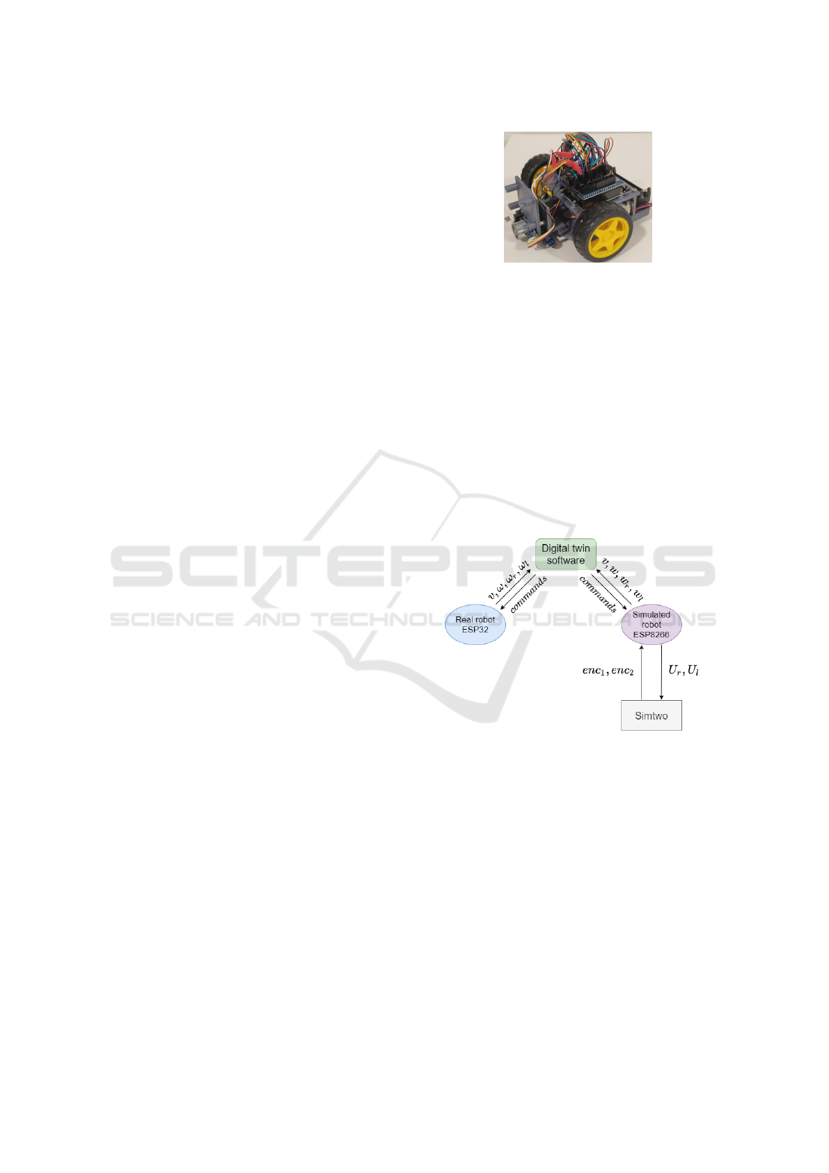
The digital twin system will work as follows:
• The real robot will operate normally.
• The simulated robot will communicate with an
ESP8266 by serial communication to perform the
hardware in the loop.
• Both of them will communicate, by UDP pro-
tocol, with monitoring software, the digital twin
software.
The entire system can be seen in Figure 2.
Figure 2: Digital twin system’s diagram.
Where v and ω are the robot’s linear and angular
speeds respectively. The right and left motors’ angu-
lar speeds are denoted by ω
r
and ω
l
. The encoder
readings are represented by enc
1
and enc
2
. Finally,
the right and left motors’ voltages are displayed by
U
r
and U
l
.
4 METHODOLOGY
SimTwo simulator was chosen for this project for
both the organization providing a simulation scene
for the competition as well as being a realistic 3D
simulator with rigid body interactions and constraints
(Paulo et al., 2011). Regarding the physics simula-
SIMULTECH 2021 - 11th International Conference on Simulation and Modeling Methodologies, Technologies and Applications
312
tion, SimTwo uses the Open Dynamics Engine (ODE)
to perform the computations (Smith et al., 2005).
To construct the simulated robot model, all the
robot’s parts were measured and weighted. The
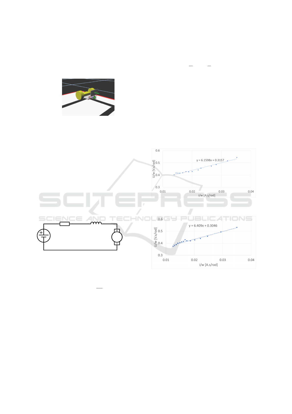
model can be seen in Figure 3.
Figure 3: Simulated robot.
4.1 Motors Models
To simulate the motor models, first, it is necessary to
obtain the DC motor parameters. Thus, steady-state
and transient tests were performed for each motor.
4.1.1 Steady State Tests
The steady-state tests were performed with the robot
in the air so that the motors’ parameters were not in-
fluenced by the robot’s weight. Before performing
the tests, it is necessary to derive the motor models.
In this way, the electric model of the armature of a
generic DC motor can be seen in Figure 4.
Ra
La
MMM
Armature
Figure 4: Electrical equivalent circuit of a DC motor’s ar-
mature.
Applying Kirchoff Voltage Law to the circuit we
have:
U = R
a
· i
a
+ L ·
di
a
dt
+ e
v
(1)
The inductance was assumed zero to simplify the
calculations. This assumption is reasonable as the
motors are small, and the equivalent armature induc-
tance is, in general, very small for small motors. The
voltage drop across the armature is e
v
, the back emf
generated by the motor while doing work, and it is
proportional to the angular speed of the shaft. The
proportionality constant is k, called the back emf con-
stant.
e
v
= k · ω (2)
Substituting equation 2 in equation 1 and dividing it
by ω we have:
U
ω
= R
a
·
i
a
ω
+ k (3)
Now, with equation 3, it is possible to perform a
series of steady-state tests where a known voltage is
applied to the motor, and its respective armature cur-
rent and the axle angular speed are measured. The
voltages were measured by a voltmeter and the cur-
rents by an ammeter. The angular speeds were esti-
mated using the embedded encoders on the motors.
In total, fifteen tests were made. The voltages ranged
from [0-6 V ], which the upper limit is the nominal
voltage for these motors. After gathering the data, a
linear model was fit to obtain the angular coefficient
R
a
and the linear coefficient k. Figures 5 and 6 show
the results from the tests performed on each motor.
Figure 5: Linear model fit to the right motor data derived
from tests applied to equation 3.
Figure 6: Linear model fit to the left motor data derived
from tests applied to equation 3.
The armature resistance and the back emf constant
from each motor can be seen in Table 1.
Applying the rotational variation of Newton’s sec-
ond law to the motor we have:
T
m
= T
q
+ B · ω +J ·
˙
ω (4)
Assuming steady-state,
˙
ω is zero. The torque
static friction is T
q
and B is the viscous friction con-
stant. The motor torque is T
m
and it is proportional
to the armature current, T
m
= k ∗ i
a
. Substituting this
equation into equation 5, and rearranging the factors
we have:
k · i
a
= B · ω + T
q
(5)
Robot@Factory Lite Competition: A Digital Twin Approach for the AGV
313
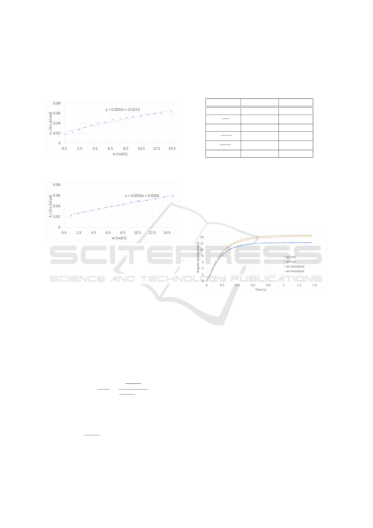
Following the same reasoning as the previous
tests, fifteen tests were performed for each motor and
a linear model was fit for each motors’ data. The right
and left motor tests can be seen in Figures 7 and 8, re-
spectively.
Figure 7: Linear model fit to the right motor data derived
from tests applied to equation 5.
Figure 8: Linear model fit to the left motor data derived
from tests applied to equation 5.
Again, from these tests, the angular coefficient
corresponds to the viscous friction and the linear co-
efficient to the torque static friction. The values of
these parameters for each motor can be seen in Table
1.
4.1.2 Transient Tests
To obtain the inertia of the motors it is necessary to
perform transient tests. They were performed with the
robot suspended on the air so that the resulting mo-
ment of inertia derived from the tests takes only into
account the contribution of the rotor plus the wheel
for each motor. The transfer function of the angular
speed of a DC motor in relation to the input voltage
can be seen in equation 6.
H(s) =
ω(s)
U(s)
=
k
BR
a
+k
2
JR
a
BR
a
+k
2
s + 1
(6)
The constants are the DC motors parameters.
Again, it was assumed that the inductance was zero
for simplicity reasons. As it can be seen, this is a
first-order system where the time constant factor is
represented by
JR
a
BR
a
+k
2
. To obtain J, a voltage step was
applied to the motors and their time constants, τ, were
measured. With them, the only unknown constant is
the moment of inertia. Thus, the time constant fac-
tor was solved for J for each motor. All the obtained
parameters, for each motor, can be seen in Table 1.
Table 1: Parameters of each DC motor.
Parameters Right motor Left motor
Ra [Ω] 6.16 6.41
k [
V.s
rad
] 0.32 0.30
Tq [N.m] 0.021 0.021
B [
N.m.s
rad
] 3.2E-03 2.6E-03
J [
N.m.s
rad
] 3.39E-03 3.42E-03
τ [s] 0.175 0.2
All these parameters, together with all the robot’s
parts dimensions and weights, were applied to the
simulation model in Simtwo. To measure the weights,
a precision scale was used. As for the dimensions, a
pachymeter. After that, transient tests were performed
on the simulated robot’s motors to see their behaviors
in respect to the same step responses applied to the
real robot. The tests applied to both robots can be
seen in Figure 9.
Figure 9: Right and left motors’ open loop step responses
from both robots.
It is clear to see from these responses that the real
robot’s motors have similar responses compared to
their respective simulated ones. Also, it is possible to
see that the real motors’ responses are different from
each other despite being applied the same step input
and being the same model. The internal structure of
the motors can influence this behavior. Although the
simulated motors behave similarly in respect of their
respective real motors, small differences are present.
These outcomes can be influenced by a series of fac-
tors such as:
• Intrinsic errors in the measurements caused by the
measurement devices (voltages, currents, angular
speeds, weights, dimensions).
• Added errors by approximation.
• Inserted errors by linear regression estimation.
• Sampling period is limited to approximately 40
ms of the execution period.
SIMULTECH 2021 - 11th International Conference on Simulation and Modeling Methodologies, Technologies and Applications
314
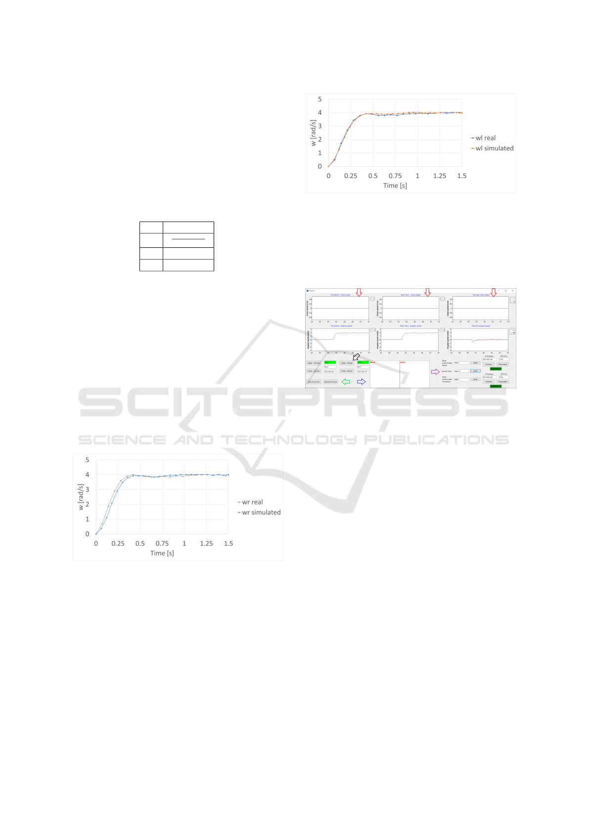
4.2 PI Controller
Simple PI controllers for angular speed were designed
for each motor of the real robot. To design the
controllers, the Internal Model Control (IMC) tuning
method was applied (Rivera et al., 1986). As our
model is a first-order system, the gains were com-
puted in the way is displayed in Table 2.
Table 2: PI controller for first order transfer function with
IMC tuning method.
PI control
Kc
τ
g
p
·[τ
cl
+t
d
]
T
i
τ
T
d
0
Where τ is the open-loop response time, g
p
is the
system’s open-loop gain, τ
cl
is the desired closed-loop
response time and, t
d
, the dead time.
The PI controllers, for both motors of the real
robot, were designed for a closed-loop time response
of 200ms, which is a similar value to the highest open-
loop time response of both motors. Deadtime was
considered zero. The values needed for the calcu-
lations were derived from the transient tests. After
computing the PI parameters, both controllers were
applied to both twins. Their motors’ behaviors were
compared by applying closed-loop step responses to
follow a 4 rad/s reference. The comparison between
the left and right motors of the twins can be seen in
Figures 10 and 11.
Figure 10: Closed loop response of the right motors of both
robots for a 4 rad/s reference.
As can be seen in the illustrations, each motor and
its respective simulated model behave similarly with
a time response of approximately 200ms. Their re-
sponses follow the reference with minimum steady-
state error and without oscillations during the whole
process.
4.3 Digital Twin
A software was developed to monitor and provide
real-time feedback of both robot’s linear and angular
Figure 11: Closed loop response of the left motors of both
robots for a 4 rad/s reference.
speeds. Thus, with the competition simulation scene,
it is possible to see the simulated robot and the real
robot performing the competition’s required tasks si-
multaneously. The software layout can be seen in Fig-
ure 12.
Figure 12: Digital twin software layout.
The charts, displayed by the red arrows in the fig-
ure, are dynamic charts that receive the robot’s speeds
through UDP communication protocol. They are or-
ganized in columns, with the first row representing
the linear speeds and the second row, the angular
speeds. The first column is data received by the simu-
lated robot. The second column, received by the real
robot. Finally, the last column represents the respec-
tive residual speeds between the twins. Regarding the
UDP communication configuration, the receiving end
is configured in the location shown by the black ar-
row. The configuration is made by simply choosing
the IP and UDP port that the software will "listen to"
to receive data from the twins. The sending end, on
the other hand, is configured where the purple arrow
is pointing at. In this location, it is possible to send
specific commands to each twin or both at the same
time. Finally, the software alerts whenever the twins’
data diverge by more than a threshold and displays
how much time the divergence endured. The alerts
show in the white boxes displayed by the blue arrow.
The left box shows linear speeds’ divergences and the
right one, angular speeds’ divergences. It is important
to emphasize that only the robot’s speeds are moni-
tored (robot’s centroid reference frame), not the indi-
vidual motors’ speeds. To avoid giving false alerts,
Robot@Factory Lite Competition: A Digital Twin Approach for the AGV
315
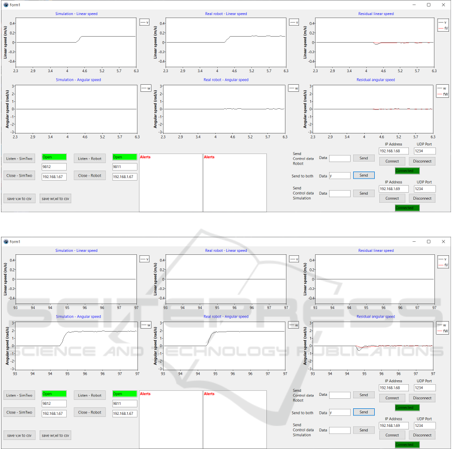
Figure 13: Real robot and digital twin response to a move straight command.
Figure 14: Real robot and digital twin response to a rotate over its own axis command.
influenced by the intrinsic noise present in both twins
and by the transient periods of the motors, the residual
data is filtered with a first-order IIR filter.
5 RESULTS
Three tests were performed to test the digital twin.
The idea behind these tests is to give the same com-
mand to both twins and analyze if they are operating
similarly. The x-axis values in the following charts
are displayed in seconds with one decimal point in all
charts. This was done to not pollute the image. The
first test was to command the twins’ motors to follow
4 rad/s angular speed references. The twins’ response
can be seen in Figure 13.
As can be seen in the illustration, both robots per-
form similarly. The robot’s angular speeds remained
0, as expected. There is a little disturbance in the
residual linear speed, which is foreseen during the
transient period. As mentioned before, there are no
alerts for two reasons, the first is that only the fil-
tered residual is analyzed. The other is that the soft-
ware must detect several times the divergence passing
a threshold before alerting that it is something wrong.
During this period, if the residual values go below the
SIMULTECH 2021 - 11th International Conference on Simulation and Modeling Methodologies, Technologies and Applications
316
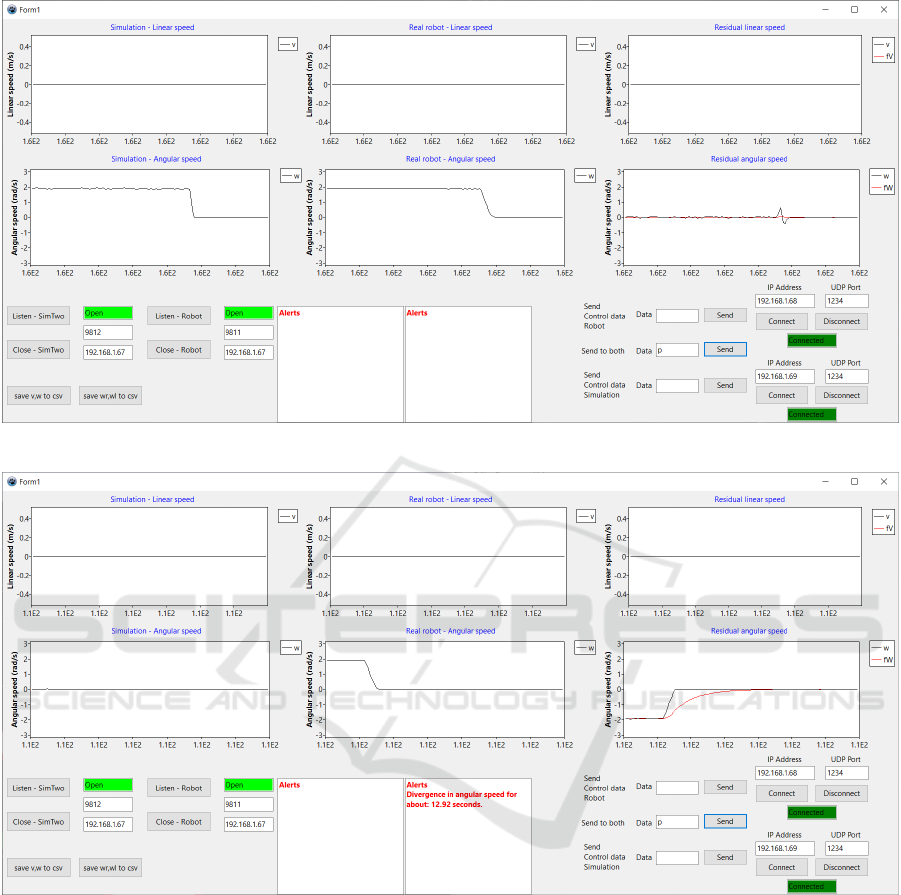
Figure 15: Real robot and digital twin response to a sudden stoppage.
Figure 16: Forced alert by stopping the simulated robot in a rotational test.
threshold, the detection counter is set to 0.
The second test was to rotate them over their rota-
tional axes by ordering one motor to follow a 4 rad/s
angular speed reference and the other a -4 rad/s ref-
erence. The robot’s behaviors can be seen in Figure
14.
This illustration shows that the robots similarly
performed the command, same as the previous test.
Their linear speeds remained 0 which is expected
since the robots did not move in any direction. Again,
the filtered residual damps the transient response and
the noise, preventing alerts. Figure 15 shows the
robot’s response to a sudden stoppage after the rota-
tional command.
As can be seen in the figure, there is a peak dur-
ing the stoppage. This happens because the robot’s
sudden stoppages, although happened in a very small
period, are different. The factors mentioned in 4.1.2,
communications in the entire digital twin system,
simulator, and different processing hardware could all
possibly influence this behavior. Note that this whole
process happened very fast as can be seen that the en-
tire charts are in the same second.
The third test was to force an alert by purposely
stopping the simulated robot. The test can be seen in
Figure 16.
Robot@Factory Lite Competition: A Digital Twin Approach for the AGV
317

In this test, the rotational command was given to
the twins. However, the motors’ voltage in the sim-
ulator was purposefully set to 0, forcing the robot to
not rotate. After giving the command to both robots
to stop, the alert appeared with the divergence’s du-
ration. This behavior is logical because when the
robot’s stopped, the divergence returned to roughly 0,
below the threshold.
6 CONCLUSIONS
This paper presented the development of a digital twin
for an AGV for the Robot@Factory Lite competition.
The robot’s motors were modeled and its parameters
were estimated. PI controllers for speed were de-
signed for each motor of the real robot. Applying the
same controllers in the simulated robot, the twins be-
haved similarly. Also, a digital twin software was pre-
sented that monitors, in real-time, the behavior of the
twins’ linear and angular speeds, alerting when they
aren’t performing similarly for some reason. The di-
vergence detection was designed to be robust to noise
and transient periods, preventing false alerts. Finally,
three tests were performed, on both twins simultane-
ously, to show the digital twin performance compared
to the real twin. The tests were sufficient to show
that the digital twin is performing very similarly, with
a negligible difference during transient periods, even
with the assumptions made for simplification during
the modeling. Therefore, the digital twin will prove
useful for the next competitions as well as by the com-
munity for other scenarios, with the instant feedback
of the robot’s performance and by greatly improving
the transition to the real scenario.
ACKNOWLEDGEMENTS
The project that gave rise to these results received
the support of a fellowship from ”la Caixa” Foun-
dation (ID 100010434). The fellowship code is
LCF/BQ/DI20/11780028. This work is financed
by National Funds through the Portuguese funding
agency, FCT - Fundação para a Ciência e a Tecnolo-
gia within project UIDB/50014/2020.
REFERENCES
Lima, J., Costa, P., Brito, T., and Piardi, L. (2019).
Hardware-in-the-loop simulation approach for the
robot at factory lite competition proposal. In 2019
IEEE International Conference on Autonomous Robot
Systems and Competitions (ICARSC), pages 1–6.
IEEE.
P33a (2020). Robot at factory lite. https://github.com/
P33a/RobotAtFactoryLite. Online; accessed 26-
February-2020.
Pairet, E., Ardón, P., Liu, X., Lopes, J., Hastie, H., and
Lohan, K. S. (2019). A digital twin for human-robot
interaction. In 2019 14th ACM/IEEE International
Conference on Human-Robot Interaction (HRI), pages
372–372.
Paulo, C., José, G., José, L., and Paulo, M. (2011). Simtwo
realistic simulator: A tool for the development and
validation of robot software. Theory and Applications
of Mathematics & Computer Science, 1(1):17–33.
Rivera, D. E., Morari, M., and Skogestad, S. (1986). Inter-
nal model control: Pid controller design. Industrial
& engineering chemistry process design and develop-
ment, 25(1):252–265.
Smith, R. et al. (2005). Open dynamics engine.
Tao, F., Zhang, H., Liu, A., and Nee, A. Y. C. (2019). Dig-
ital twin in industry: State-of-the-art. IEEE Transac-
tions on Industrial Informatics, 15(4):2405–2415.
Tao, F., Zhang, M., Liu, Y., and Nee, A. (2018). Digital twin
driven prognostics and health management for com-
plex equipment. Cirp Annals, 67(1):169–172.
Weyer, S., Meyer, T., Ohmer, M., Gorecky, D., and Züh-
lke, D. (2016). Future modeling and simulation of
cps-based factories: an example from the automotive
industry. Ifac-Papersonline, 49(31):97–102.
Zhang, H., Liu, Q., Chen, X., Zhang, D., and Leng, J.
(2017). A digital twin-based approach for designing
and multi-objective optimization of hollow glass pro-
duction line. IEEE Access, 5:26901–26911.
SIMULTECH 2021 - 11th International Conference on Simulation and Modeling Methodologies, Technologies and Applications
318
