A Novel Method for the Real-time Force Losses Detection in Servo
Welding Guns
D. Ibáñez
1
a
, E. García
2
b
, J. Martos
1
c
and J. Soret
1
d
1
Dept. of Electrical and Electronic Engineering, University of Valencia, Burjassot, Valencia, Spain
2
Ford Valencia, 46440, Valencia, Spain
Keywords: Resistance Spot Welding, Bending, Real-time, Automatization, Force Control, Welding Gun.
Abstract: Nowadays, real-time detection methods are increasingly necessary for predictive maintenance in production
processes. Specifically, in the metal joining production processes that use the resistance welding process, the
optimization of maintenance programs is sought to improve both the quality of the body and its manufacturing
cost. In this novel paper a new method is presented for the sensorless detection of pressure losses in welding
lines. The proposed system bases its operation on the measurement of the existing variables in the resistance
welding process carried out using servo guns. This paper also shows the proposed system for the data
acquisition, data sending and visualization in real-time of the health of the welding gun. This results in a
system with a low installation cost but with great performance in reducing problems associated with force
losses in welding guns.
1 INTRODUCTION
The resistance welding process is currently the most
widely used metal joining process, especially in the
automotive industry, where this process represents
around 90% of the joints made in a car body.
(Koskimäki et al., 2007; Yu et al., 2014; Hwang et al.,
2013). Despite the great use of this process, the
resistance welding process is highly complex, since
this process involves different fields such as
electromagnetism, thermodynamics, metallurgy and
mechanics. (Li et al., 2007). Due to the importance of
this process in the metallurgical industry, specifically
in the automotive manufacturing industry, it is
essential to guarantee the welding quality of each of
the joints carried out during the production process.
The quality of the joint of each of the joints that
are made through the resistance welding process is
determined by the diameter of the weld nugget. This
diameter is directly reflected in the joint design shear
load requirement.
Depending on the specific characteristics of the
joint, type and thickness of the metal, the type of
a
https://orcid.org/0000-0002-3917-9875
b
https://orcid.org/0000-0002-4210-9835
c
https://orcid.org/0000-0002-8455-6369
d
https://orcid.org/0000-0001-8695-6334
welding transformer and electrode from the welding
gun, several different parameters are required to form
the desired weld nugget that meets the quality
requirements.
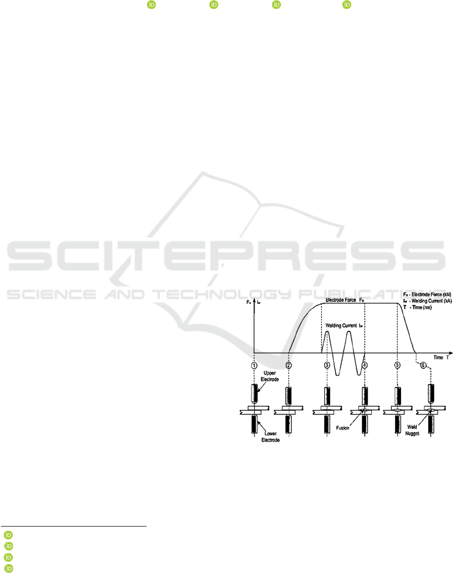
Figure 1: Spot welding process.
The three main parameters that can be controlled to
obtain adequate quality in RSW are welding current,
electrode force and welding time (Willian and Parket,
2004).
Ibáñez, D., García, E., Martos, J. and Soret, J.
A Novel Method for the Real-time Force Losses Detection in Servo Welding Guns.
DOI: 10.5220/0010549006690676
In Proceedings of the 18th International Conference on Informatics in Control, Automation and Robotics (ICINCO 2021), pages 669-676
ISBN: 978-989-758-522-7
Copyright
c
2021 by SCITEPRESS – Science and Technology Publications, Lda. All rights reserved
669
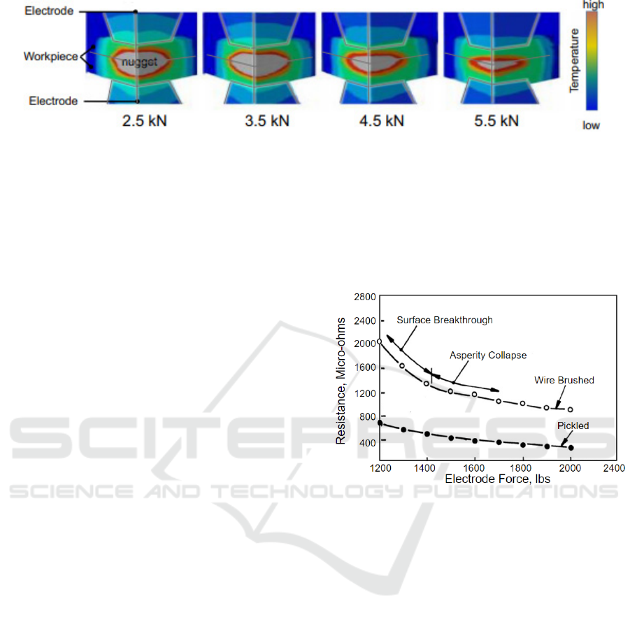
Figure 2: Influence of the electrode force on the temperature distribution (Kobayashi & Mihara, 2014).
Resistance welding is carried out according to the
following process: the electrodes are closed at a
determined force by squeezing the metal sheets to be
welded. Once the programmed force is reached, it is
maintained for a short period to eliminate any gaps
that may exist between the sheets.
The welding current then flows through the
electrodes supplying energy to contacting workpieces.
Through the Joule effect, electrical energy is
transformed into heat gradually spreading through the
junction. Upon reaching the melting temperature, a
liquid nugget is formed that grows as a function of
welding time. Once the pre-set time has been reached,
the welding current stops, and then the electrodes are
released. Finally, the melting nugget solidifies, and the
weld is formed. (Kang & Lilong, 2014).
Consequently, as long as it is not influenced by
other external parameters, the welding current, the
force applied by the electrodes and the welding time
determine the heat given to the joint and therefore,
they directly influence the final quality of the welds.
Different authors speak of the importance of force
in the final quality of the weld, emphasizing the need
to guarantee a certain force. (Lucas, 2003; Norrish,
2006; Brijesh, 2014).
As mentioned, resistance welding bases its
operation on the Joule heat represented by equation 1.
𝐻=
𝐼
𝑡
𝑅
𝑡
𝑑𝑡
(1)
where H is the amount of heat energy generated
during the process, I(t) is the welding current, R(t) is
the dynamic resistance of the sheet metals, T1 and T2
are the beginning and ending times of the operation,
respectively (Henry,1910).
Resistivity for metals is usually considered to be
independent of force. In contrast, in resistance
welding, the contact resistance has a relationship with
the force distribution, in addition to the variation of
the contact surface conditions.
In general, due to irregularities in the electrode
and the metal sheets to be welded, only a small part
of the apparent contact area is in actual contact.
During resistance spot welding the force created by
the compression of the electrode breaks these
irregularities and causes a decrease in contact
resistance. this was demonstrated during the studies
Dickinson’s research and can be clearly seen in figure
1. Hence, not high enough electrode force cannot be
able to create enough electrical contact at the
interfaces and can cause concentrated heating and
possibly local melting or even expulsions.
Figure 3: Relationship between dynamic resistance and
electrode force (Dickinson, 1981).
Expulsion is a phenomenon that occurs when the
expansion of the weld nugget exceeds the force of the
supplied electrode, this causes an ejection of the
molten metal from the weld zone during welding. due
to force caused by the expansion of the weld nugget
exceeds supplied electrode force. Furthermore, as the
electrode force decreases, the diameter of the welding
nugget increases and the resistance of the weld until
ejection occurs (Zhang et Al.2009).
The contact resistance is also influenced by the
surface condition of the metal sheets. The presence of
Oil, dirt or any other foreign content causes a change
in the resistance. The effects on contact resistance of
these foreign contents decrease rapidly after the force
of an electrode is applied. The contact surfaces have
peaks and valleys. When subjected to low force,
metal-to-metal contact will be only the peaks. The
resulting contact area is less than that produced by an
appropriate force. Therefore, the contact resistance
will be greater, causing a greater amount of heat to be
generated.
ICINCO 2021 - 18th International Conference on Informatics in Control, Automation and Robotics
670
In short, it could be summarized as the lower the
force, the greater the interfacial resistance, which
results in a greater generation of heat at the tip-to-
sheet and sheet-to-sheet interfaces.
Then, it can be stated that the welding force plays
a crucial role in the quality of the final joint. (Zhang
& Senkara,2005) (Wang & Wei,2001).
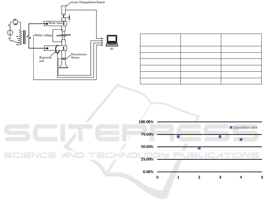
Figure 4: Schema piezoelectric sensor.
Currently, the measurement of force loss in real
welding lines presents a series of drawbacks
depending on the method used for this detection.
First, the use of piezoelectric sensors or strain
gauges gives good results in welding lines but
represents too high a cost, which, in most cases,
makes their installation unfeasible (Podržaj et al,
2011) as seen in the figure 4.
Secondly, this measurement can be carried out
with manual dynamometers, in the same way, this
method provides a reliable result and more versatility
since the same dynamometer can be used for all
welding guns because this function is done through
an operator. The main problem of this method is that
the data is not available in real-time, so it is necessary
to carry out preventive maintenance, generating
personnel costs.
In short, there is currently no truly implantable
method for detecting force losses in welding guns for
high production factories.
For this reason, this research proposes the use of
stiffness measurement to create a real-time
measurement system integrated into the welding lines
for the detection of force losses.
2 EXPULSION AND FORCE IN
REAL WELDING LINES
For a first evaluation of the relationship between
force and the presence of projections in a real welding
line.
For this, a welding gun that due to force problems
has begun to present a high number of expulsions is
evaluated. Specifically, this welding gun performs 13
welding points on a specific part of the body, the tests
are carried out on an electric welding gun, ServoGun.
The phase difference between the real force of the
gun and the nominal force programmed is measured
with a dynamometer. This makes it possible to assess
the state of the welding gun and the influence on
expulsions.
Table 1: Nominal and Real Forde before calibration.
Nominal Force
[DaN]
Real Force
[DaN]
Difference
[DaN]
150 77 73
200 93 107
250 111 139
300 131 169
350 157 193
400 192 258
Once the state of the welding gun has been
determined, the data of average projections during
production are taken, obtaining the data measured in
figure 6.
Figure 5: Expulsion rate before force calibration.
As can be seen, the expulsion data is above the
usual and adequate values for optimum quality. Thus,
a force calibration is performed to reduce the
difference between the nominal force and the actual
force.
It is assumed that initially the weld was
programmed with an adequate force and that,
therefore, when the force returned to its original
value, a notable reduction in expulsions will be
observed.
After performing the calibration, the real and
nominal force data and the difference between them
are taken again, in order to observe the improvement
in force and the relationship with the improvement in
the expulsion rate. These data are shown in table 2.
It can be seen that when carrying out the
calibration, the difference between the nominal force
and the real force is significantly reduced so that the
A Novel Method for the Real-time Force Losses Detection in Servo Welding Guns
671

Table 2: Nominal and Real Forde after calibration.
Nominal Force
[DaN]
Real Force
[DaN]
Difference
[DaN]
150 152 2
200 202 2
250 262 12
300 310 10
350 355 5
400 417 17
force applied to the weld joint will be more similar to
the programmed force.
In the same way, as in the previous case, the data
on the expulsion rate is taken during the manufacture
of four parts of the body by the same welding gun,
obtaining the results shown in figure 7.
Figure 6: Expulsion rate after force calibration.
As can be seen from the comparison between
figures 6 and 7. The problems due to lack of force
cause an increase in expulsions in the production
lines, causing an increase in the expense for the repair
and cleaning of the welded parts. For this reason, the
interest in finding a system for the real-time detection
of force losses increases.
3 FORCE AND BENDING IN
REAL WELDING LINES
In order to obtain a viable method for the detection of
lack of force, the measurement of the bending of the
arms of the welding guns is considered.
Different authors have studied the measurement
of the encoder of the servomotors and the influence
of the bending on the real value of the electrode
position.
Specifically, some authors established a
relationship between the measurement of the position
of the electrodes and the indentation of the weld. (Yu-
Jun et al.,2020).
In welding guns, the fixed electrode arm of a
servo gun can be considered as a cantilever beam with
limited stiffness, this means that a non-negligible
deviation can occur in the arm of the fixed electrode
(Tang et al., 2003).
As Yun et al. show in their research, the fixed arm
can be simplified and reduced into three parts and P3,
as shown in figure 7 each considered as a beam of
uniform cross-section. This means that the bending
moment M
z
is distributed evenly along the direction
length of the part P3, this happens in the same way
with the axial force F
x
. Therefore, the longitudinal
surface deformation of the piece P3 can be considered
constant Fig 8.
If the theory of elasticity is followed, the
longitudinal surface deformation ε
3x
and deflection D
f
of the electrodes can be calculated following equation
(2)(3). where F is the force of the electrode, E refers
to the elastic modulus of the beam, A1 and A3 are the
cross-sectional areas of part G1 and G3, l2 is the
length of the piece G2, w3 is the width or diameter of
the cross-section of the part G3, I2 and I3 are the
moments of inertia of part G2 and part G3,
respectively. γ and λ are the proportionality
coefficients between ε3x and F, Df and F,
respectively.
ε
=
=𝛾𝐹
𝛾=
(2)
𝐷
=
=λ𝐹
λ=
(3)
Figure 7: Schema Force in fixed arm.
From the previous equations (2)(3) a relevant
conclusion can be drawn for this study, and this
conclusion is that there is a proportional relationship
between the force and the deflection marked by the
ICINCO 2021 - 18th International Conference on Informatics in Control, Automation and Robotics
672
proportionality variable λ. Therefore, if the
relationship between deflection and force is
established, the pressure variations can be determined
based on the variations in deflection. To see the real
behaviour in a welding line, the electrode
displacement data is taken in a welding gun installed
in a production line.
For this, the electrodes are closed without any
metal sheet between them, in such a way that if it is
considered that there is no influence of the force, this
position should remain stable despite the changes in
force. However, as it has been explained if this
relationship exists, it is expected to observe how as
the force of the electrodes increases, therefore, their
closing position increases.
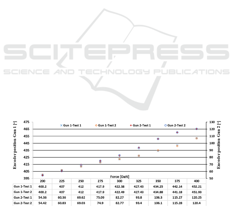
This test is carried out on a ServoGun, in such a
way that the position value can be obtained directly
from the encoder rotation value, shown in degrees
Fig9. The behaviour of two different welding guns
located on different production lines is analysed. In
the first one (Gun 1) it can be seen how as the force
increases, the position of the encoder increases,
behaving almost proportionally (R
2
=0.988).
Similarly, if the encoder position curve generated
by the change in force for gun 2 is analysed, it can be
stated that it also presents a linear behaviour, but, in
this case, there is a greater slope of the curve, that is,
this welding gun features a greater displacement for
the same force range.
In both cases, the behaviour between the
displacement of the electrode and the force is affine.
Since, as it was deduced from equations 2 and 3, the
displacement is proportional to the force, but also the
encoder adjustment component must be taken into
account, since the position of 0 degrees should be
equal to a force of 0 kN, but sometimes due to a bad
configuration, the zero of the encoder does not
coincide with the real zero of the welding gun, when
the electrodes are in contact without applying
pressure.
As result, two main conclusions can be drawn
from this real experiment: First, in a real welding gun
the elasticity law is fulfilled and there is a relationship
between the bending and the displacement of the
electrodes. Second, the ratio between electrode
displacement and force is not necessarily the same for
all welding guns, depending on the mechanical and
physical characteristics of each one.
4 METHOD FOR DETECTING
LOSS OF FORCE
The method investigated in this paper bases its
operation on the measurement of the displacement of
the electrode for the detection of force losses. As
explained in the previous section, there is a linear
relationship between the bending of the arms of the
welding electrodes and the force applied to them. This
method is specially designed for the detection of
power losses in servo welding guns.
Since there is a real relationship between the
position of the electrode and the force applied on
them, a system for measuring the position of the
electrodes at different forces is designed. In such a
way that possible variations in position could be
monitored in real-time.
The measurement system is carried out as follows:
First, the PLC sends the order to change the
electrodes to the robot. After carrying out this change
of electrodes, the gun is sent to carry out the first
milling to avoid shear problems when making the
measurements.
Once the milling is finished, the wear of the
electrodes stored in the robot is reset. When all this
Figure 8: Real relationship between force and encoder position.
A Novel Method for the Real-time Force Losses Detection in Servo Welding Guns
673
process has been carried out, the electrodes are in the
optimal state to begin with the measurement of the
force loss following the newly proposed method.
Figure 9: Schema measure operation.
To measure force wear, the electrodes are closed
by pressing a 20mm thick metal piece Fig 10. In such
a way that if the real position reached by the
electrodes is measured, it will represent how much
they have bent.
Specifically, two measures are carried out, the
first of them executing a low force and the second of
them executing a force at the maximum capacity of
the welding gun. This is due to the fact that, on
occasions, the welding guns lose force in a certain
range, that is, the wear of the force does not occur
equally in all the command forces.
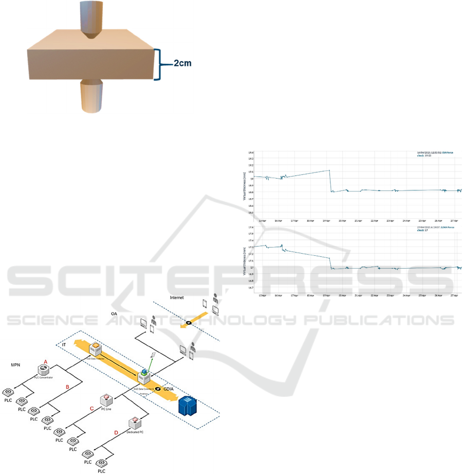
Figure 10: Real-Time data collection Schema (Garcia &
Montes, 2019).
Once these measurements are obtained, they are
sent to the PLC. The PLC, upon receiving the position
measurements, sends them labelled to the Rslinx and
through the MQTT protocol they are stored in a
database to be analysed.
To send and display these data, the same system
used by Garcia & Montes (2019) for data acquisition
from PLCs in real-time in factories is used.
5 REAL CASE
IMPLEMENTATION
This method is being tested in a real welding line on
which real-time data of force wear is being collected.
In this specific case, the programming was done
on a Kuka KRC4 robot with an ARO ServoGun 3G
pistol. For this, the check-up was programmed as
described in the previous section and began with the
acquisition and sending of data for its analysis.
In the first place, it can be observed in figure 11
how when working at a higher pressure (3.5kN), the
virtual thickness detected by the method is less than
in the case of low pressure (1kN) since the deflection
of the arms is directly proportional to force.
Figure 11: Historical data of the force check position
measurements.
After a period of time of correct operation of the
method, the pressure was checked according to
traditional methods, using a dynamometer. This
check showed that there was a lag of -300DaN
between the nominal pressure and the real pressure so
the calibration was carried out. As can be seen in
figure 11, as of April 19, once the calibration was
carried out, it was verified that when adjusting the
pressure by increasing the pressure, a change was
experienced in the virtual thickness measured. That is
to say, in short, the method is capable of detecting
pressure changes in real welding guns.
This leads to the expectation that when the high
force begins to wear out, the value of the position will
begin to approach the value of the low force position.
Approaching the minimum position value
established, which in this case is 20 mm due to the
thickness of the part on which the electrodes are
closed.
In short, data monitoring has begun, hoping that
as wear occurs in the welding gun, the system will be
able to detect them.
ICINCO 2021 - 18th International Conference on Informatics in Control, Automation and Robotics
674

With all that is exposed throughout this section, it
can be affirmed that the method is capable of
detecting power loss problems in welding guns
without the need for an external sensor, only using the
existing variables in robotized servo guns.
6 CONCLUSION
Throughout the paper, the importance of the force
parameter in the resistance welding process has been
shown, emphasizing the influence of force losses and
the appearance of expulsions.
The need to measure force losses and the
difficulty in applying current methods to carry out
force detection in large production factories has also
been discussed throughout the paper.
For all this, a novel method has been presented for
the real-time detection of force losses based on the
relationship between bending and the applied force.
This method provides the following advantages over
the previous methods:
• Reduced implementation costs: It is only
necessary to program the robot and the data
collection system. As it is a method based on the
analysis of variables of the servo gun welding
gun, it is not necessary to acquire any type of
additional sensor.
• Real-time measurement system: The system
proposed for the implementation of the method
makes it possible to view the data at any time,
being possible to generate alarms as soon as the
loss of force occurs.
• Maintenance cost reduction: since the force
value is acquired directly from the welding line,
it is not necessary to carry out any other type of
maintenance to determine force losses, so
preventive maintenance plans carried out can be
reduced.
In short, throughout this paper, a response has
been given to a problem that exists in factories that
produce metal joints that use servo guns for resistance
welding. It is expected that future research will
present optimizations to the method and success cases
for the final validation of the method.
ACKNOWLEDGEMENTS
The authors wish to thank Ford España S.A, in
particular, the Almussafes factory for their support in
the present research. The authors also wish to extend
their thanks to the "Foundation for Development and
Innovation of the Valencian Community (FDI)".
REFERENCES
Koskimäki, P. Laurinen, E. Haapalainen, L. Tuovinen, and
M. Juha Röning, “Application of the extended knn
method to resistance spot welding process
identification and the benefits of process information,”
IEEE Trans. Indus. Electron. 54(5), 2823–2830 (2007).
J. Yu, D. Choi, and S. Rhee, “Improvement of weldability
of 1 GPa grade twin-induced plasticity steel,” Welding
J. 93(3), 78s–84s (2014).
G. Hwang, P. Podrzaj, and H. Hashimoto, “Note:
Resistance spot welding using a microgripper,” Rev.
Sci. Instrum. 84(10), 106105-1–3 (2013).
Y. B. Li, Z. Q. Lin, S. J. Hu, and G. L. Chen, “Numerical
analysis of magnetic fluid dynamics behaviors during
resistance spot welding,” J. Appl. Phys. 101(05),
053506 (2007)
N. T. Williams and J. D. Parker, “Review of resistance spot
welding of steel sheets Part 1 Modelling and control of
weld nugget formation,” Int. Mater. Rev. 49(2), pp. 45–
75, (2004).
Zhou, Kang & Cai, Lilong. (2014). Study on effect of
electrode force on resistance spot welding process.
Journal of Applied Physics. 116. 084902-084902.
10.1063/1.4893968.
W Lucas Ph.D., DSc, CEng, FIM, FWeldl, EWE, S
Westgate BSc(Hons), in Electrical Engineer's
Reference Book (Sixteenth Edition), (2003)
John Norrish, in Advanced Welding Processes, (2006).
Brijesh, Makwana, M. Desai, Mr. Pradhyuman Parmar and
P. Student. “Optimization of process parameters for
Resistance Spot Welding process of Austenitic SS 304
using Response Surface Method – A Review.” (2014).
Crew, Henry. General Physics: an elementary textbook
FOR colleges, 2nd Edition. The University of
Michigan: The Macmillan Company. pp. 402–404.
(1910).
Zhang, H. & Senkara, J. Resistance welding: Fundamentals
and applications. (2005).
Wang, S. & Wei, P., Modeling Dynamic Electrical
Resistance During Resistance Spot Welding. Journal of
Heat Transfer-transactions of The Asme - J HEAT
TRANSFER. 123. 10.1115/1.1370502. (2001)
X. Zhang, G. Chen, Y. Zhang and X. Lai, “Improvement of
resistance spot weldability for dual-phase (DP600) steel
using servo gun”, Journal of Materials Processing
Technology, pp 2671-2675, (2009).
Kobayashi T, Mihara Y (2014) Numerical simulation of
nugget formation in spot welding: Mechanical Design
& Analysis Corporation. SIMULIA Community
Conference 2014:1–15
Dickinson, D. W., "Welding in the Automotive Industry",
American Iron and Steel Institute. Research Report SG
81-5. August (1981).
A Novel Method for the Real-time Force Losses Detection in Servo Welding Guns
675

Podržaj, Primož & Simončič, Samo. Resistance spot
welding control based on fuzzy logic. The International
Journal of Advanced Manufacturing Technology. 52.
959-967. 10.1007/s00170-010-2794-0. (2011).
Xia, Yu-Jun & Su, Zewei & Lou, Ming & Li, Yongbing &
Carlson, Blair. Online Precision Measurement of Weld
Indentation in Resistance Spot Welding Using Servo
Gun. IEEE Transactions on Instrumentation and
Measurement.69.4465-4475. 10.1109 /TIM.2019.2943
981. (2020).
H. Tang, W. Hou, S. J. Hu, H. Y. Zhang, Z. L. Feng, and
M. Kimchi, "Influence of welding machine mechanical
characteristics on the resistance spot welding process
and weld quality," Welding Journal, vol. 82, no. 5, pp.
116S-124S, 2003.
E. Garcia, N. Montes, Mini-term, a novel paradigm for fault
detection, IFAC-PapersOnLine, Volume 52, Issue 13,
Pages 165-170, ISSN 2405-8963. (2019).
ICINCO 2021 - 18th International Conference on Informatics in Control, Automation and Robotics
676
