
TEdit: A Distributed Tetrahedral Mesh Editor with Immediate
Simulation Feedback
D. Str
¨
oter
1 a
, U. Krispel
2,3 b
, J. S. Mueller-Roemer
1,4 c
and D. W. Fellner
1,3,4 d
1
TU Darmstadt, Interactive Graphics Systems Group, Germany
2
Fraunhofer Austria Research GmbH, Austria
3
TU Graz, Institute of Computer Graphics and Knowledge Visualization, Austria
4
Fraunhofer IGD, Darmstadt, Germany
Keywords:
Computer Aided Design, Simulation Environments, Client Server Architectures, Massively Parallel and
High-performance Simulations.
Abstract:
The cycle of computer aided design and verification via physics simulation is often burdened by the use of
separate tools for modeling and simulation, which requires conversion between formats, e.g. meshing for finite
element simulation. This separation is often unavoidable because the tools contain specific domain knowledge
which is mandatory for the task, for example a specific CAD modeling suite. We propose a distributed appli-
cation that allows interactive modification of tetrahedral meshes, derived from existing CAD models. It pro-
vides immediate simulation feedback by offloading resource-intensive tasks onto multiple machines thereby
enabling fast design cycles for individualized versions of mass-produced parts.
1 INTRODUCTION
Due to the persistent high cost, 3D printing is still
not an option for mass production. However, it is in-
creasingly used for individualized versions of mass-
produced parts (D., 2018), albeit limited to purely
cosmetic parts. To create custom versions of parts
with a mechanical function, simulations of the modi-
fied part are required to ensure that it continues to ful-
fill its function. However, the usual iterative product
development cycle of modifying a part in computer-
aided design (CAD), remeshing it, and simulating it
in a computer-aided engineering (CAE) tool is uneco-
nomic in this context.
We present TEdit, a novel tetrahedral mesh edi-
tor with immediate simulation feedback, i.e. without
tool switches or manual intervention and with min-
imal delay. By making use of the fact that high-
quality tetrahedral meshes and corresponding sim-
ulation load cases already exist for mass-produced
parts, we significantly shorten the product develop-
a
https://orcid.org/0000-0002-2672-7377
b
https://orcid.org/0000-0001-8984-635X
c
https://orcid.org/0000-0002-0712-0457
d
https://orcid.org/0000-0001-7756-0901
ment cycle for customized parts. By directly editing
the tetrahedral mesh—not the CAD model—and us-
ing its triangular surface for printing, editing of the
CAD model followed by full remeshing is avoided
completely. GPU-accelerated simulation provides di-
rect feedback (Sec. 2), while client hardware require-
ments are minimized using a multi-tier, distributed
client-server architecture (Sec. 3). We developed a
set of tetrahedral mesh editing operations that aim
to preserve mesh quality, while maintaining the se-
mantic relationship between boundary triangles that
originally formed a CAD surface or form a new, con-
tiguous surface after an edit to improve user interac-
tion (Sec. 4).
2 RELATED WORK
Currently, there is little literature on tetrahedral mesh
editing. Stoll et al. (Stoll et al., 2007) explore in-
teractive shape editing of volumetric meshes using
linear deformation with differential rotation updates.
In order to enable intuitive interaction, they provide
deformation-handles for users to grab. As our frame-
work is designed for virtual prototyping, interaction
Ströter, D., Kr ispel, U., Mueller-Roemer, J. and Fellner, D.
TEdit: A Distributed Tetrahedral Mesh Editor with Immediate Simulation Feedback.
DOI: 10.5220/0010544402710277
In Proceedings of the 11th International Conference on Simulation and Modeling Methodologies, Technologies and Applications (SIMULTECH 2021), pages 271-277
ISBN: 978-989-758-528-9
Copyright
c
2021 by SCITEPRESS – Science and Technology Publications, Lda. All rights reserved
271
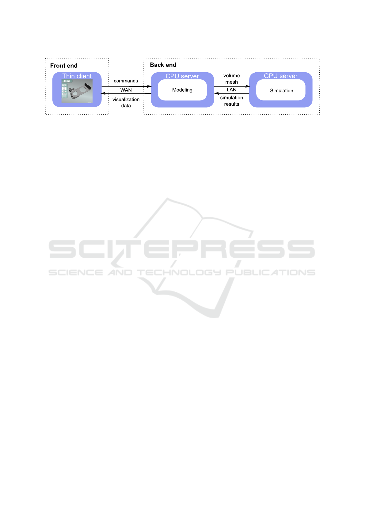
Figure 1: The system is composed of three main services, which may reside on different machines. This separates the
interactive visualization front end from CPU-intensive geometry modification and GPU-intensive simulation tasks.
is a based on semantic faces to enable intuitively ap-
plying model modifications that go beyond deforma-
tions, such as hole closing. Mezger et al. (Mezger
et al., 2009) propose to deform tetrahedral meshes
using physically based simulation. Through the us-
age of a finite element method (FEM) model they
avoid significant change in volume. In contrast, the
goal of our work is a set of editing operations that
enable adding or removing model parts, i.e. chang-
ing model topology. For engineering purposes, Serna
et al. (Serna et al., 2010) propose an embodiment of
the FEM mesh to allow manipulation of semantic fea-
tures. Thus, engineers are able to perform extrusion,
rounding or dragging operations on high-level seman-
tic features. Our editing framework also relies on
high-level semantic features to provide intuitive inter-
action, but directly imports explicit high-level faces
from CAD models to provide intuitive user interac-
tion. Xian et al. (Xian et al., 2011) present a mesh
editing framework for finite element analysis (FEA)
purposes. They decompose the mesh into local fea-
tures representing the semantic meaning of parts, e.g.
holes or protrusions. Editing operations such as de-
formations respect feature constraints and preserve
element quality. Their editor does not support load
distribution of compute intensive tasks due to execu-
tion on a single machine. In contrast, our tetrahe-
dral mesh editor is distributed, enabling execution on
the best-suited machines. A related geometry edit-
ing application is Inria’s Graphite (Inria, 2019). Like
TEdit, Graphite enables users to fill holes and delete
mesh facets in volumetric meshes. Its automatic hole
detection can be controlled by a threshold of max-
imum boundary vertices. While Graphite focuses
on 3D modeling and numerical optimization, TEdit
is specifically designed to accelerate virtual proto-
typing, providing immediate (see Sec. 1) simulation
feedback and interaction with semantic faces defined
in CAD.
To achieve direct, low-latency simulation feed-
back, we use a fully GPU-accelerated FEA code
based on the merged kernel modified precondi-
tioned conjugate gradient (MPCG) solver by We-
ber el al. (Weber et al., 2013) and the fast tetra-
hedral system assembly method by Mueller-Roemer
and Stork (Mueller-Roemer and Stork, 2018). As
Mueller-Roemer and Stork’s method not only per-
forms element stiffness matrix assembly on the GPU,
but also determines the system matrix sparsity pattern
efficiently in parallel, it is highly beneficial when not
only tetrahedral mesh geometry, but also topology, is
modified during editing. Weber et al.’s fast MPCG,
a GPU-optimized version of Baraff and Witkin’s
MPCG (Baraff and Witkin, 1998), minimizes kernel
launch overheads and allows simulation of multiple
sets of boundary conditions without having to assem-
ble a new system matrix.
While we use a GPU-accelerated linear static solid
mechanics simulation in our prototype, other acceler-
ators, such as FPGAs, or different physical domains
could be used with our approach, as long as the simu-
lation code supports tetrahedral meshes.
3 ARCHITECTURE
The following points were considered in the design
decisions for the architecture of the proposed system:
The resource demand of the complete application is
high, as mesh processing for larger meshes needs high
single-core CPU performance and a large amount of
RAM, the fast FEA requires a capable GPU, and the
visualization part puts additional load on CPU and
GPU performance as well. Thus, the approach is to
create a distributed application instead of a mono-
lithic one by grouping related components into ser-
vices. These services communicate using a network
protocol, which allows to run components on differ-
ent machines and distribute the work load to comput-
ers with adequate hardware equipment. Thus, the re-
quirements for the front end consist largely of what
is needed for visualization and interaction. This ap-
proach also ensures a degree of encapsulation be-
tween existing components. In addition, simulation
is overlapped with user interaction further reducing
perceived latency. Communication takes place us-
SIMULTECH 2021 - 11th International Conference on Simulation and Modeling Methodologies, Technologies and Applications
272
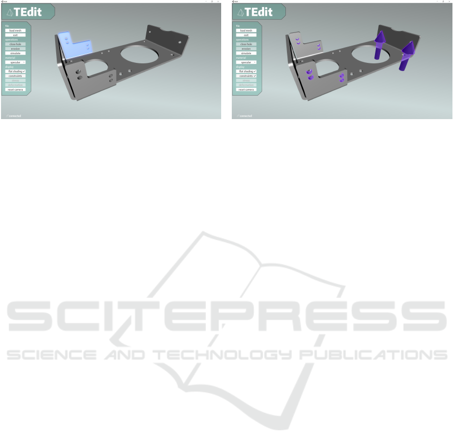
Figure 2: A user may quickly select relevant model parts, as a selection interaction automatically selects triangle groups, such
as ones that originate from a single CAD surface (left). Furthermore, simulation load cases are visualized by highlighting
surfaces, such as constrained surfaces, or surfaces with applied forces (right).
ing WebSockets, in order to facilitate easy integra-
tion into various front end implementations such as
web browsers, to facilitate the use and dissemina-
tion of CAD visualizations (Krispel et al., 2018). An
overview of services and communication is shown in
Fig. 1.
3.1 Workflow and Communication
The front end service presents the model to the user
in an interactive manner. The user may select parts
of the model and perform an editing operation. The
modification command and its parameters are sent to
the modeling back end where the topological modi-
fications are performed; results are sent back to the
front end. At the same time, the updated mesh is sent
to the simulation service and simulation of the previ-
ously selected load case is started. After simulation,
the selected field is sent back to the front end.
Although simulation has to be performed on the
tetrahedral representation, the outer surface triangles
of the tetrahedral mesh are sufficient for visualiza-
tion. Thus, the main data for communication from
the front end’s point of view consists of modeling
commands with model part selections upstream, and
surface and simulation data downstream. On the
back end side, the modeling service sends tetrahedral
meshes to the simulation service, and receives simu-
lation results, such as scalar fields on the mesh. To
minimize (de)serialization and bandwidth overhead,
we use an efficient binary protocol based on Protocol
Buffers (Google, 2020).
One challenge with a distributed modeling sys-
tem is the synchronization of model state between the
services. In our implementation, the front end ser-
vice communicates only with the modeling service
on the back end side, the modeling service commu-
nicates with the simulation service using the tetrahe-
dral mesh representation (see Fig. 1). Operations and
visualization updates are carried out asynchronously,
to keep the user interface responsive during modeling
and simulation. A user may issue one command be-
fore a response is received, while still being able to
navigate and inspect the model.
3.2 Front End
Game engines have gained in popularity for develop-
ment of 3D interfaces in many areas outside of games,
as they provide solid frameworks for rapid develop-
ment of interactive 3D applications. We chose the
Unity platform (Unity, 2020) for implementing our
front end service. The viewer consists of an interac-
tive 3D rendering and a navigation interface in which
the user inspects and modifies the model, or inspects
simulation load cases and simulation results (see Fig-
ure 2). The system maintains an association of trian-
gle to groups, such as those originating from a single
CAD face or editing operation, facilitating selection
of such semantic groups for fast interaction with the
model.
When sending a command message, the front end
service puts itself into a waiting mode; command but-
tons are disabled until a reply is received, but the
model can still be rotated or moved.
3.3 Modeling and Simulation Services
To enable optimal use of hardware for tetrahedral
mesh editing, which typically requires a large amount
of RAM and high single-core performance, and sim-
ulation, which requires an NVIDIA GPU in our
case (Sec. 2), but is not limited by single core per-
formance, the back end is further split into a model-
ing service and a simulation service. This results in
a distributed, multi-tier client-server architecture, as
the modeling service acts as a server for the front end,
while acting as a client for the simulation service. The
client therefore only communicates with the modeling
service directly (Fig. 1).
TEdit: A Distributed Tetrahedral Mesh Editor with Immediate Simulation Feedback
273

While the front end only requires the boundary
mesh, as well as simulation results (see Figs. 3 and 4
in the following section), for selection and visualiza-
tion, both modeling and simulation operate on tetra-
hedral meshes. Therefore, the front end can be remote
and connected via a high-latency, low-bandwidth con-
nection (latency-free interaction remains possible due
to asynchronous operation), but both back end ser-
vices should run in the same data center for low-
latency, high-bandwidth communication, as full vol-
umetric meshes are exchanged.
4 GEOMETRY EDITING
To avoid forcing the user to interact with individual
boundary triangles, TEdit uses CAD surface IDs to
associate every boundary triangle with its originating
CAD surface. This information is provided directly
by hierarchical meshers such as Gmsh (Geuzaine and
Remacle, 2009). Surface IDs are preserved through-
out the editing operations described in the following.
Additionally, a mapping telling the client which sur-
faces were added, removed, or merged is generated
and used to update both constraint visualizations as
well as boundary conditions for the simulation tool.
4.1 Volumetric Hole Filling
We present an algorithm for filling holes in the model,
for example to remove unneeded drill holes or holes
that were included for weight saving, but turned out
to introduce large stresses. An example is shown in
Fig. 3. Users may select a set of surfaces represent-
ing the shell of a drill hole. On the back end side,
such a shell is associated with a non-manifold trian-
gular surface mesh that is part of the tetrahedral mesh.
We present an algorithm to fill selected holes in the
tetrahedral mesh’s surface by performing the follow-
ing four steps:
1. Detect boundary loops in the surface mesh of the
selected triangles
2. Two-dimensional constrained meshing for each
boundary loop
3. Three-dimensional constrained meshing using the
resulting 2-manifold surface
4. Merge the resulting volume mesh with the mesh
representing the model
Specifically, the service identifies selection bound-
ary loops by finding edges which are topologically
connected to just one triangle and sorting these. A
simple sorting procedure for boundary loops is to
pick an arbitrary initial boundary edge and search for
the next adjoining edge until the initial edge recurs.
We accelerate boundary loop identification by sorting
edges by indices and successively marking edges be-
longing to a loop. Whenever this sorting procedure
finds a boundary loop, it searches for an unmarked
edge indicating that there is an unidentified bound-
ary loop. If such an edge exists, it is the new ini-
tial boundary edge for another boundary loop iden-
tification pass. Otherwise the procedure terminates
and returns the obtained boundary loop edges with
array offset positions. For each boundary loop, we
project the boundary vertices onto the plane includ-
ing the co-planar boundary edges, in order to apply
a two dimensional constrained Delaunay triangulator
for hole filling. In TEdit, we use Shewchuck’s Trian-
gle library (Shewchuk, 1996), but our concept gener-
alizes to arbitrary constrained Delaunay triangulation
schemes. After meshing terminates, the resulting tri-
angulation is transformed to 3D and merged with the
triangular surface shell of the drill hole. The result-
ing triangular surface mesh is 2-manifold. Hence, a
three-dimensional constrained Delaunay triangulator
can be used to generate a tetrahedral mesh of the hole.
We use the TetGen library (Si, 2015) in this project.
Finally, we merge the newly generated tetrahedra and
vertices with the original tetrahedral mesh. For this
purpose, it suffices to reassign original vertex indices
to shared vertices and assign consecutive indices to
newly generated vertices.
4.2 Erosion
Our erosion algorithm enables users to remove plate-
like parts of the model or reduce thickness, while pre-
serving mesh quality. Figure 4 shows an example. On
the front end side, users may select surfaces—triangle
groups—for erosion. The modeling service receives
a set of surface triangles from which erosion is sup-
posed to start. In order to preserve adjacent seman-
tic surfaces, we identify the boundary vertices of the
triangle set and omit them beforehand. Our erosion
scheme marks tetrahedra including any input vertex
as to be deleted. In order to prevent erosion from
retaining groups of tetrahedra not connected to the
initial part, we propagate a flood fill from tetrahedra
which are definitely not removed from the initial part,
i.e. tetrahedra belonging only to unselected seman-
tic faces. We mark tetrahedra not reached by flood
fill for deletion. The triangles of the new surface can
be found by checking if triangles are connected to a
marked and an unmarked tetrahedron. We identify
vertices to be deleted by marking vertices not belong-
ing to a marked tetrahedron. An exclusive prefix sum
SIMULTECH 2021 - 11th International Conference on Simulation and Modeling Methodologies, Technologies and Applications
274
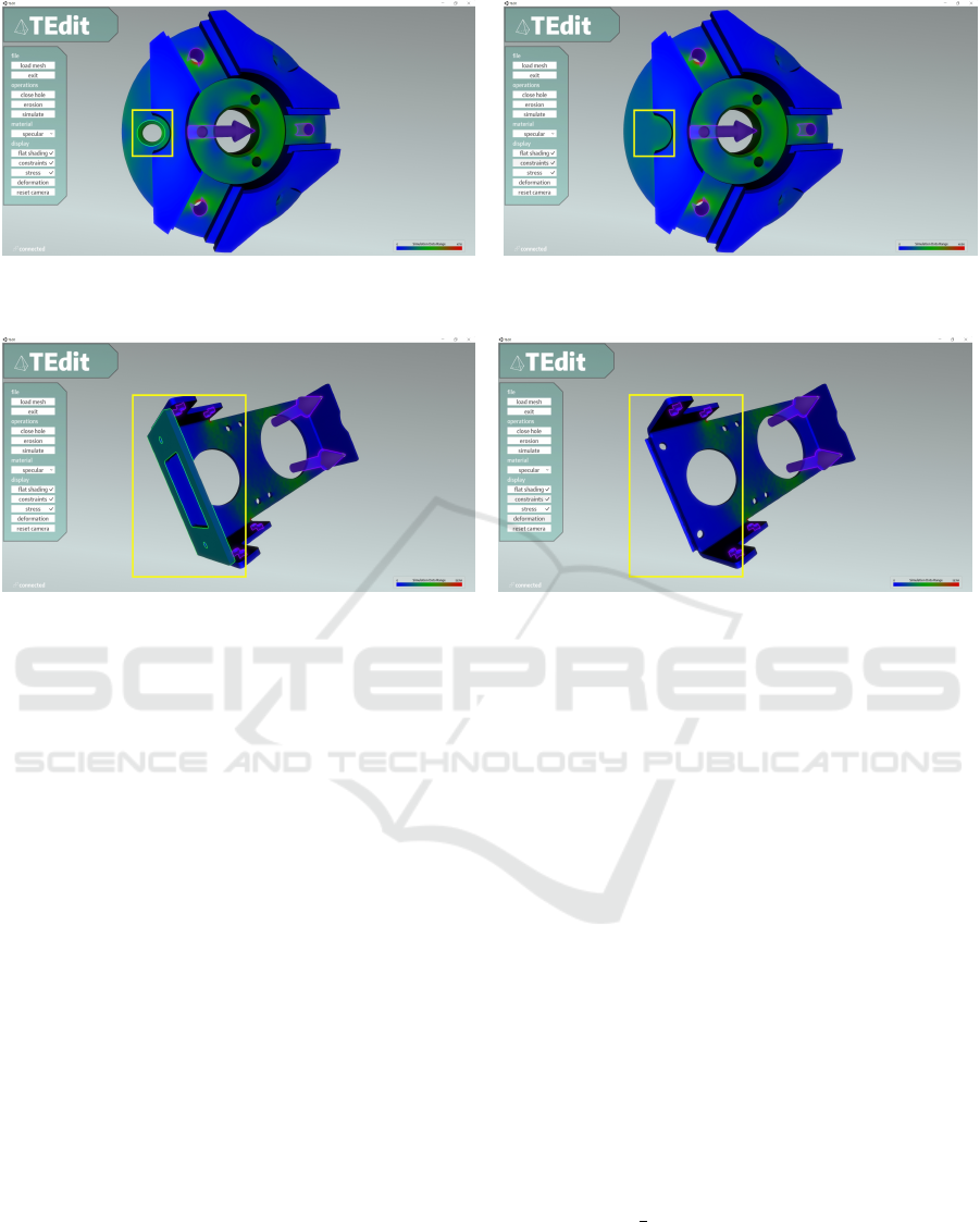
Figure 3: Von Mises stress before (left) and after (right) filling the selected hole (highlighted in yellow). The model was
provided by N. M. Patel via GrabCAD (Patel, 2020).
Figure 4: Von Mises stress before (left) and after (right) eroding the selected part of the model (highlighted in yellow). The
model is part of the ABC dataset (Koch et al., 2019).
on marked vertices yields their array index positions.
This is used to update the indices of the remaining
tetrahedra.
When erosion terminates, a coarse surface with
tetrahedra protruding from the surface remains. How-
ever, we aim to create a smooth surface. At the same
time, the resulting tetrahedral mesh must be free of
ill-formed and degenerate tetrahedra for simulation.
Consequently, we perform a quality-optimization-
based surface smoothing method after element ero-
sion. This method performs a combination of topo-
logical transformations and optimization-based vertex
smoothing due to the substantial advantage over us-
ing just a single optimization operation (Klingner and
Shewchuk, 2008). We build upon harmonic triangu-
lation by Alexa (Alexa, 2019) for mesh optimization,
as it is effective in removing slivers and improving di-
hedral angles with a small set of optimization opera-
tions, i.e. bistellar flips and vertex position relocation.
As many tetrahedra have four boundary vertices, our
optimization method initially checks, if performing a
bistellar 2 to 3 flip at an interior face improves qual-
ity. If it does, we perform the flip. After flipping,
we improve mesh quality by performing line search
for each single interior vertex in a Gauss-Seidel itera-
tions manner. The next step is to smooth the surface
by computing the cotangent Laplacian (Nealen et al.,
2006) gradient. In forward-backward Gauss-Seidel it-
erations, we use bracketing to find an inversion-free
position for the boundary vertex. If no such position
can be found, the vertex remains at its position and
may be updated by following iterations. In addition
to preventing inversions, it can also be ensured that
the resulting tetrahedra shall not exceed a predeter-
mined quality threshold. We alternate flipping, inte-
rior vertex optimization, and surface smoothing for
one or more iterations.
4.3 Element Quality
A single ill-shaped element can cause a simulation to
fail (Shewchuk, 2002). In addition, the FEM does
not work, if the tetrahedral mesh includes inverted el-
ements or elements of infinitesimally small volume.
Consequently, we evaluate the element quality of the
meshes modified using our geometry editing algo-
rithms. Table 1 presents volumes and aspect ratios—
calculated as inradius over circumradius, resulting in
a range of [0,
1
3
] (Cheng et al., 2012)—of the result-
ing meshes for both editing operations. Hole fill-
ing produces a mesh with high quality aspect ratios.
No infinitesimally small volume tetrahedra occur in
the resulting mesh. Moreover, the resulting elements
exhibit non negative volumes. The erosion opera-
TEdit: A Distributed Tetrahedral Mesh Editor with Immediate Simulation Feedback
275

Table 1: Maximum, minimum, and median volumes and
aspect ratios (higher is better) of the meshes shown on the
left hand sides (before) and right hand sides (after) of Fig. 3
(hole fill) and Fig. 4 (erosion).
Volume Aspect Ratio
Edit Op. Max. Min. Med. Max. Min. Med.
Before Hole Fill 3.3e-10 1.4e-11 1.1e-10 .3333 .0803 .2737
After Hole Fill 2.4e-9 1.4e-11 1.1e-10 .3333 .0456 .2736
Before Erosion 1.6e-10 5.4e-12 4.9e-11 .3333 .0872 .2688
After Erosion 1.6e-10 1.0e-12 4.9e-11 .3333 .0004 .2689
tion with six iterations of subsequent quality preserv-
ing surface smoothing did not introduce inverted ele-
ments or infinitesimally small volume tetrahedra. The
resulting tetrahedra exhibit sufficient aspect ratios. As
a result, both mesh editing operations succeed at pro-
ducing meshes suitable for the FEM, as we have also
validated in our experiments.
5 CONCLUSIONS
In summary, we have introduced a novel tetrahedral
mesh editor with immediate simulation feedback. By
directly operating on CAE meshes, modifications can
be performed and simulated, while avoiding switch-
ing to a CAD tool and remeshing the entire domain.
As 3D printing can support and often only supports
discrete triangular surfaces, this approach avoids hav-
ing to feed back the results into a CAD tool com-
pletely. While the current set of editing operations
is somewhat limited, our prototype demonstrates how
the iterative product design loop can be shortened for
individualized versions of mass-produced parts.
The use of a GPU-accelerated FEA solver ensures
short iteration times, while the distributed architec-
ture minimizes user hardware requirements. Due to
the use of Unity (Unity, 2020) and WebSockets, the
front end can be deployed directly as a web applica-
tion. Bandwidth requirements are low due to the use
of surface meshes only between the front end and the
modeling service (the modeling and simulation ser-
vice should reside in the same data center, as they ex-
change volumetric meshes).
As the implemented editing operations preserve
the correspondence between individual boundary tri-
angles and their originating CAD surface IDs (or a
newly created contiguous surface ID), the user can in-
teract at a significantly higher level of abstraction than
individual surface triangles. Furthermore, this allows
automatic remapping of surface-based boundary con-
ditions for simulation. Additionally, mesh optimiza-
tion ensures mesh quality is preserved.
5.1 Future Work
Besides the extension to further editing operations, it-
eration times could be further reduced in the future by
performing geometry processing on the GPU, as done
by Mueller-Roemer et al. (Mueller-Roemer et al.,
2017). While our local, topological erosion works
well for the removal of fin- or plate-like structures,
the addition of geometric morphological operations,
such as the opening and closing operations on trian-
gle meshes recently shown by Sell
´
an et al. (Sell
´
an
et al., 2020), could greatly improve the flexibility of
the editor. Furthermore, hole filling could be extended
to non-planar holes by reparametrization of the loop
into 2D space and subsequent determination of inte-
rior point positions in 3D by solving a Laplacian.
REFERENCES
Alexa, M. (2019). Harmonic triangulations. ACM Transac-
tions on Graphics, 38(4):1–14.
Baraff, D. and Witkin, A. (1998). Large steps in cloth
simulation. In Proceedings of the 25th annual con-
ference on Computer graphics and interactive tech-
niques, SIGGRAPH ’98, pages 43–54.
Cheng, S.-W., Dey, T. K., and Shewchuk, J. (2012). Delau-
nay mesh generation. CRC Press.
D., J. (2018). Mini offers 3D printing person-
alization services for its cars. [Online; ac-
cessed Dec-2020]. https://www.3dnatives.com/en/
3d-printing-mini-100120184/.
Geuzaine, C. and Remacle, J.-F. (2009). Gmsh: A 3-d finite
element mesh generator with built-in pre- and post-
processing facilities. International Journal for Nu-
merical Methods in Engineering, 79(11):1309–1331.
Google (2020). Protocol buffers. [Online; ac-
cessed Dec-2020]. https://developers.google.com/
protocol-buffers/.
Inria (2019). Graphite. [Online; accessed Dec-
2020]. http://alice.loria.fr/index.php?option=com
content&view=article&id=22.
Klingner, B. M. and Shewchuk, J. R. (2008). Aggressive
tetrahedral mesh improvement. In Proceedings of the
16th International Meshing Roundtable, pages 3–23.
Koch, S., Matveev, A., Jiang, Z., Williams, F., Artemov, A.,
Burnaev, E., Alexa, M., Zorin, D., and Panozzo, D.
(2019). ABC: A big CAD model dataset for geomet-
ric deep learning. In 2019 IEEE/CVF Conference on
Computer Vision and Pattern Recognition.
Krispel, U., Settgast, V., and Fellner, D. W. (2018). Dy-
namo - dynamic 3d models for the web: A declara-
tive approach to dynamic and interactive 3d models
on the web using x3dom. In Proceedings of the 23rd
International ACM Conference on 3D Web Technol-
ogy, Web3D ’18, New York, NY, USA. Association
for Computing Machinery.
SIMULTECH 2021 - 11th International Conference on Simulation and Modeling Methodologies, Technologies and Applications
276

Mezger, J., Thomaszewski, B., Pabst, S., and Straßer, W.
(2009). Interactive physically-based shape editing.
Computer Aided Geometric Design, 26(6):680–694.
Mueller-Roemer, J. S., Altenhofen, C., and Stork, A.
(2017). Ternary sparse matrix representation for vol-
umetric mesh subdivision and processing on GPUs.
Computer Graphics Forum, 36(5):59–69.
Mueller-Roemer, J. S. and Stork, A. (2018). GPU-based
polynomial finite element matrix assembly for sim-
plex meshes. Computer Graphics Forum, 37(7):443–
454.
Nealen, A., Igarashi, T., Sorkine, O., and Alexa, M. (2006).
Laplacian mesh optimization. In Proceedings of the
4th international conference on Computer graphics
and interactive techniques in Australasia and South-
east Asia, pages 381–389.
Patel, N. M. (2020). Simple mechanical part 7. [Online;
accessed Dec-2020]. GrabCAD Community, https://
grabcad.com/library/simple-mechanical-part-7-1.
Sell
´
an, S., Kesten, J., Sheng, A. Y., and Jacobson, A.
(2020). Opening and closing surfaces. ACM Trans-
actions on Graphics, 39(6):1–13.
Serna, S. P., Stork, A., and Fellner, D. W. (2010). Tetrahe-
dral mesh-based embodiment design. In International
Design Engineering Technical Conferences and Com-
puters and Information in Engineering Conference.
Shewchuk, J. (2002). What is a good linear finite ele-
ment? interpolation, conditioning, anisotropy, and
quality measures (preprint). University of California
at Berkeley, 73:137.
Shewchuk, J. R. (1996). Triangle: Engineering a 2d quality
mesh generator and Delaunay triangulator. In Applied
Computational Geometry Towards Geometric Engi-
neering, pages 203–222.
Si, H. (2015). TetGen, a Delaunay-based quality tetrahedral
mesh generator. ACM Transactions on Mathematical
Software, 41(2):1–36.
Stoll, C., de Aguiar, E., Theobalt, C., and Seidel, H.-P.
(2007). A volumetric approach to interactive shape
editing. Technical Report MPI-I-2007-4-004, Max-
Planck-Institut f
¨
ur Informatik.
Unity (2020). Unity real-time development platform. [On-
line; accessed Dec-2020]. https://unity.com/.
Weber, D., Bender, J., Schnoes, M., Stork, A., and Fellner,
D. W. (2013). Efficient GPU data structures and meth-
ods to solve sparse linear systems in dynamics appli-
cations. Computer Graphics Forum, 32(1):16–26.
Xian, C., Gao, S., and Zhang, T. (2011). Tetrahedral mesh
editing with local feature manipulations. In 2011 12th
International Conference on Computer-Aided Design
and Computer Graphics, pages 130–137.
TEdit: A Distributed Tetrahedral Mesh Editor with Immediate Simulation Feedback
277
