
From 2D to 3D Mixed Reality Human-Robot Interface in Hazardous
Robotic Interventions with the Use of Redundant Mobile Manipulator
Krzysztof Adam Szczurek
1,2 a
, Raul Marin Prades
2 b
, Eloise Matheson
1 c
, Hugo Perier
1
,
Luca Rosario Buonocore
1 d
and Mario Di Castro
1 e
1
European Organization for Nuclear Research, Switzerland
2
Jaume I University of Castellon, Spain
Keywords:
Human-Robot Interface, Robotics, Teleoperation, Virtual Reality, Mixed Reality, Operator Workload,
Galvanic Skin Response.
Abstract:
3D Mixed Reality (MR) Human-Robot Interfaces (HRI) show promise for robotic operators to complete tasks
more quickly, safely and with less training. The objective of this study is to assess the use of 3D MR HRI
environment in comparison with a standard 2D Graphical User Interface (GUI) in order to control a redundant
mobile manipulator. The experimental data was taken during operation with a 9 DOF manipulator mounted in
a robotized train, CERN Train Inspection Monorail (TIM), used for the Beam Loss Monitor robotic measure-
ment task in a complex hazardous intervention scenario at CERN. The efficiency and workload of an operator
were compared with the use of both types of interfaces with NASA TLX method. The usage of heart rate
and Galvanic Skin Response parameters for operator condition and stress monitoring was tested. The results
show that teleoperation with 3D MR HRI mitigates cognitive fatigue and stress by improving the operators
understanding of both the robot’s pose and the surrounding environment or scene.
1 INTRODUCTION
In the environment where there are risks for human
operators such as presence of radiation or magnetic
fields, or lack of oxygen in underground/underwater
areas, the robotic operations can be indispensable.
Nowadays, the most commonly used interfaces to
control robots in radioactive scenarios are 2D GUIs
with keyboard/joystick inputs and camera feedback.
However, thanks to the development of sensors, com-
munication, electronics and faster computation, 3D
interfaces, which show the world as we see with our
eyes, can bring multiple advantages in terms of addi-
tional information available to the operator and mak-
ing the operation more efficient.
To describe the purpose of the research on the
Mixed Reality Human-Robot Interface at CERN, first
a specific project and the teleoperation task have to
be explained. One of the tasks executed with the aid
of robots at CERN is to verify Beam Loss Monitors
(BLMs) signal condition with a radioactive source ap-
a
https://orcid.org/0000-0002-2440-5956
b
https://orcid.org/0000-0002-2340-4126
c
https://orcid.org/0000-0002-1294-2076
d
https://orcid.org/0000-0001-5396-2519
e
https://orcid.org/0000-0002-2513-967X
proached to the monitors in the Large Hadron Col-
lider (LHC) tunnels. Its complexity lies in the need
of full perception of the configuration of the robot,
robot’s position in the surrounding area, approach to
the device and collision avoidance, which all are cru-
cial during the intervention.
1.1 Motivation
At CERN, an ongoing project is to verify that each
of 4500 BLMs located in the LHC is functioning
correctly. Currently, these measurements are per-
formed manually by an expert who brings a radioac-
tive source, held via a tool that they hold, close to
the monitor (BLM), and checks that the device is
responding correctly. This methodology has a few
drawbacks. It is time-consuming due to the number
of devices, and due to the difficulty of the approach.
Some of the BLMs are located next to a pathway
(Figure 1), but others can be hidden behind the mag-
nets or equipment. Another disadvantage is that the
expert operator will absorb some radiation. There-
fore, it was proposed to replace the manual measure-
ments via a robotic system. Specifically, the project is
to use the Train Inspection Monorail (TIM) (Di Cas-
tro et al., 2018b) as a platform to transport a robotic
manipulator which can reach most the the BLMs in
388
Szczurek, K., Prades, R., Matheson, E., Perier, H., Buonocore, L. and Di Castro, M.
From 2D to 3D Mixed Reality Human-Robot Interface in Hazardous Robotic Interventions with the Use of Redundant Mobile Manipulator.
DOI: 10.5220/0010528503880395
In Proceedings of the 18th International Conference on Informatics in Control, Automation and Robotics (ICINCO 2021), pages 388-395
ISBN: 978-989-758-522-7
Copyright
c
2021 by SCITEPRESS – Science and Technology Publications, Lda. All rights reserved
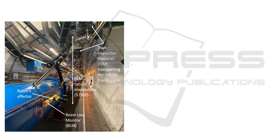
the Large Hadron Collider (LHC) tunnels. An il-
lustration of the robotic task is shown in Figure 1,
where the BLM robotic manipulator end effector ap-
proaches a BLM installed on the magnet dipole in the
LHC. The manipulator is attached to the TIM (Fig-
ure 4) platform which travels on a rail mounted on
the tunnel ceiling. In order to have enough range and
approach flexibility, a redundant robotic manipulator
with 9 degrees of freedom has been designed (Figure
1). The operation is ultimately planned to be executed
either semi-autonomously via teleoperation, or fully
autonomously. However, the use of the robot presents
multiple challenges, including:
1. Collisions and self-collisions due to limited per-
ception of the environment and robot’s pose;
2. Manipulator redundancy and singularities;
3. Limited bandwidth and coverage of connectivity;
4. Targets (BLMs) not being visible at the beginning
of the approach and not precisely located in the
design model.
Figure 1: Approach with the BLM robotic manipulator in
the LHC tunnel.
1.2 State of the Art
The CERNTAURO robotic framework developed at
CERN for autonomous and supervised teleoperations
in harsh environments is presented in (Di Castro et al.,
2018a). The system was tested in tens of real inter-
ventions and demonstrated efficiency and flexibility
in the executed tasks. The extension of the system
with cooperative teleoperation and multi-robot inter-
face is explained in (Veiga Almagro et al., 2020). The
cooperative behaviour was tested with the CERN-
TAURO project at CERN and with the TWINBOT
project in an underwater scenario and proved that
one operator can handle an intervention with mul-
tiple robots in a safe way. Furthermore, a prelim-
inary study of Virtual Reality Interface for guiding
underwater robots in the TWINBOT project (de la
Cruz et al., 2020) was carried out and and feasibil-
ity and usability tests of the VR HRI module were
done. A depth estimation vision system based on
tracking metallic objects was tested with the CERN
HRI is described in (Almagro et al., 2019). It presents
an operator-supervised method with AR elements to
facilitate teleoperated manipulation tasks. The dif-
ficulty of dealing with reflections from metallic sur-
faces was solved.
The subject of hyper-redundant robots is dis-
cussed in (Andr
´
es Mart
´
ın Barrio, 2020) where the
author discusses the problems with modelling and
control when teleoperating such robots. Different
problematic aspects are discussed, including those re-
lated to redundancy, such as inverse kinematics so-
lutions, pose awareness and human-robot interfaces.
They found that immersive human-robot interfaces
provided significantly better efficiency, situational
awareness and visual feedback. The impact of the
use of a set of ”interaction tools” was also measured.
They concluded that the use of a physical VR con-
troller had a relatively high efficiency, however the
use of gestures and voice commands had better per-
formance.
Another study (Chacko and Kapila, 2019), which
focused on AR solutions, presented how visual feed-
back from a camera can be merged with additional
information from object recognition algorithms, de-
creasing the workload of the operator. The small mea-
sured workload and simplicity indicated potential ad-
vantages that could be applied in the experiments pre-
sented in this paper.
The telepresence can be affected by many factors
such as latency, frame of reference, field of view and
frame rate. These parameters can lower the perfor-
mance and create issues. How vision and interaction
fidelity affected spatial cognition and workload in im-
mersive interfaces is studied in (Almeida et al., 2020).
The results give recommendations how telepresence
improvement techniques impact the operator’s effort.
1.3 Paper Structure
Section 2 presents the overall architecture of the
CERN robotic systems and the ”2D” and ”3D”
Human-Robot Interfaces. Section 3 describes the ex-
periments undertaken with the interfaces and operator
monitoring sensors. Finally, Section 4 summarizes
the work, results from the experiments and presents
a road-map for future developments.
From 2D to 3D Mixed Reality Human-Robot Interface in Hazardous Robotic Interventions with the Use of Redundant Mobile Manipulator
389
2 SYSTEM DESCRIPTION
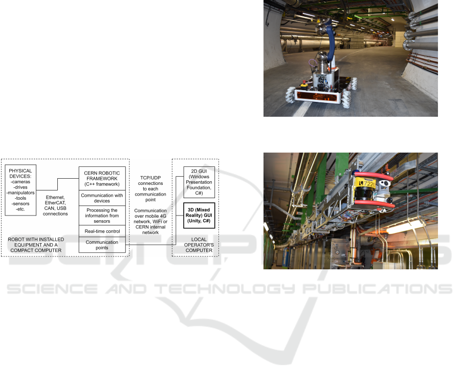
The overall architecture of the robot’s control system
is presented in Figure 2. The system is composed of
two subsystems. The first is a robot with its configura-
tion of physical devices connected to a compact com-
puter with a Linux operating system. The computer
runs the CERN Robotic Framework, which is a C++
set of programs that operate devices and communi-
cates with the external world, including the processes
responsible for real-time control of motors, arms, sen-
sors and cameras. The second sub-system is the oper-
ator’s side, composed of the Human-Robot Interface
in the form of either the 2D CERN Robotic GUI (de-
veloped with WPF technology in C#) or the 3D Mixed
Reality GUI (developed in Unity, in C#), both running
on a Windows machine. In the diagram in Figure 2,
the part of the system which has been newly devel-
oped for this research is highlighted in bold.
Figure 2: Architecture diagram of the robot control.
2.1 2D CERN Robotic GUI
Currently, the operational control of the robots at
CERN is performed with the CERN Robotic GUI,
which is an application connecting directly to the
robot via WiFi, using CERN’s internal network or via
a VPN running of the 4G mobile network. The user
has the ability to:
• Customize the robot’s configuration for a mission;
• Control the movement of a robot’s base (i.e.
the omnidirectional platform shown in Figure 3,
monorail train shown in Figure 4);
• Control a robotic manipulator in joint and Carte-
sian coordinate systems (base and tool refer-
ences);
• See video streams from different types of cameras
(RGB, depth, thermal) and record them;
• Control tools (i.e. gripper) and have sensor feed-
back (i.e. force sensor);
• Perform semi-autonomous tasks like unfolding
the manipulator, approaching a defined/recorded
position;
• Control the robot with different input devices
(keyboard, gamepad, space mouse).
The architecture of the core of the CERN Robotic
GUI has been fully described in the Section IV in
(Lunghi et al., 2019).
Figure 3: Omnidrectional robotic platform with an installed
arm.
Figure 4: Train Inspection Monorail which can haul spe-
cialized wagons i.e. with a manipulator.
A control view with the robot’s control inputs and
views from the cameras is shown in Figure 5. On the
left vertical ribbon, there are tabs to switch between
different views to control the robot’s base, arm, cam-
eras, state machine and change the settings of the ap-
plication. For the arm control, in the upper right cor-
ner, the two control modes (joint and Cartesian) can
be toggled. In the lower right corner, different input
devices (keyboard, space mouse or gamepad) can be
selected. In the area on the bottom, the current in-
put device panel is presented. In the upper left corner,
there is the cameras selection tool, which streams are
placed in the upper and center parts of the window.
2.2 3D Mixed Reality GUI
The Mixed Reality Human-Robot Interface for con-
trolling robots with real-time feedback has been de-
veloped and experimentally tested. At CERN, oper-
ators are using mouse and keyboard control input on
weekly basis for robotic interventions. Whilst these
inputs devices are not novel, they are very reliable,
well-understood and give the operator full trust and
ICINCO 2021 - 18th International Conference on Informatics in Control, Automation and Robotics
390
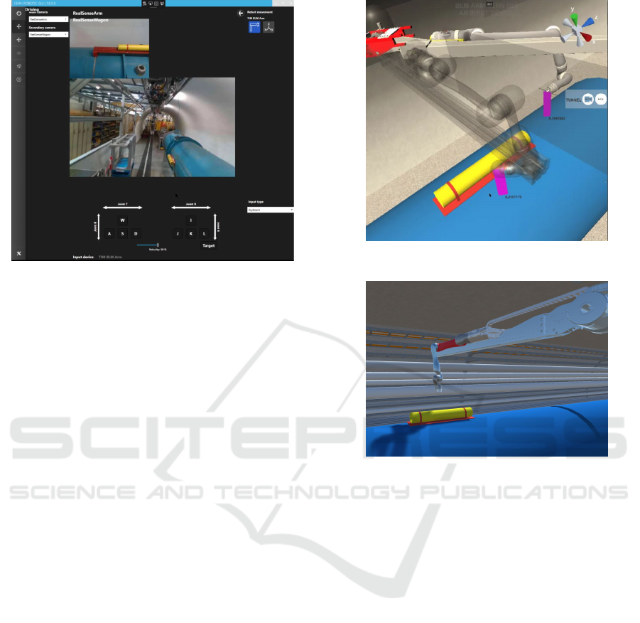
Figure 5: CERN Robotic GUI control view with an arm’s
control and cameras view, keyboard control.
high-resolution control options. Other input devices
such as gesture recognition and voice control and very
interesting to further study to understand their appli-
cability in real-case scenarios, but are not the subject
of this research paper. The main functionalities that
have been already implemented are:
• Visualization of the robot’s pose in relation to a
modelled environment visible from any perspec-
tive;
• Planning of the next position and sending a com-
mand to move when it’s ready;
• Real-time control of the robot and its manipulator;
• Camera streaming in the 3D scene.
In the Figure 6 a planning mode is used to first
position the arm (the transparent model) for the best
approach, and then launch the movement in joint con-
trol. In Figure 7, real-time control is used with imme-
diate commands and feedback reading. The operator
can select which joint to move.
The second possible mode is real-time control
where the command is send immediately to the robot
to execute and the current positions are read con-
stantly from the robot. In Figure 7 the operator can
select a joint marked in red and change the angle to
approach the target.
Apart from joint coordinate system control, the
end effector can be steered in the Cartesian world or
tool coordinate systems. In Figure 8 there are 3 illus-
trations, the first depicts a gizmo that can be moved
and rotated by dragging it with a mouse, the second
shows a gizmo that controls only the rotation and the
third shows translation motion only. As the manipu-
lator consists of 9 joints (a redundant system), it was
concluded that only the inverse kinematics (IK) con-
Figure 6: VR control of the arm in the planning mode.
Figure 7: VR control of the arm in the real-time control
mode, the active joint is marked in red.
trol of the last 6 joints is needed, while the first 3 joints
can be controlled in joint space. This limits the com-
plexity and decreases the computational time of the
IK algorithm, while still allowing the operator enough
workspace to complete the task.
The arm can be controlled with the use of the in-
teractive markers presented in the scene (Figure 9),
presenting the direction of the joint movement, its an-
gle and clickable controls.
3 EXPERIMENTS
An experiment was conducted to evaluate the use of
the 3D environment and its effect on the operator’s
workload and efficiency compared to the use of the
standard GUI with the 2D interface. In the 3D envi-
ronment, the operator could see not only the streams
from cameras but also the real-time model of the
the robot and the offline environment that was pre-
pared before the intervention. The model of the robot
was placed in the environment according to measure-
ments of the setup. In this experiment, there was no
From 2D to 3D Mixed Reality Human-Robot Interface in Hazardous Robotic Interventions with the Use of Redundant Mobile Manipulator
391
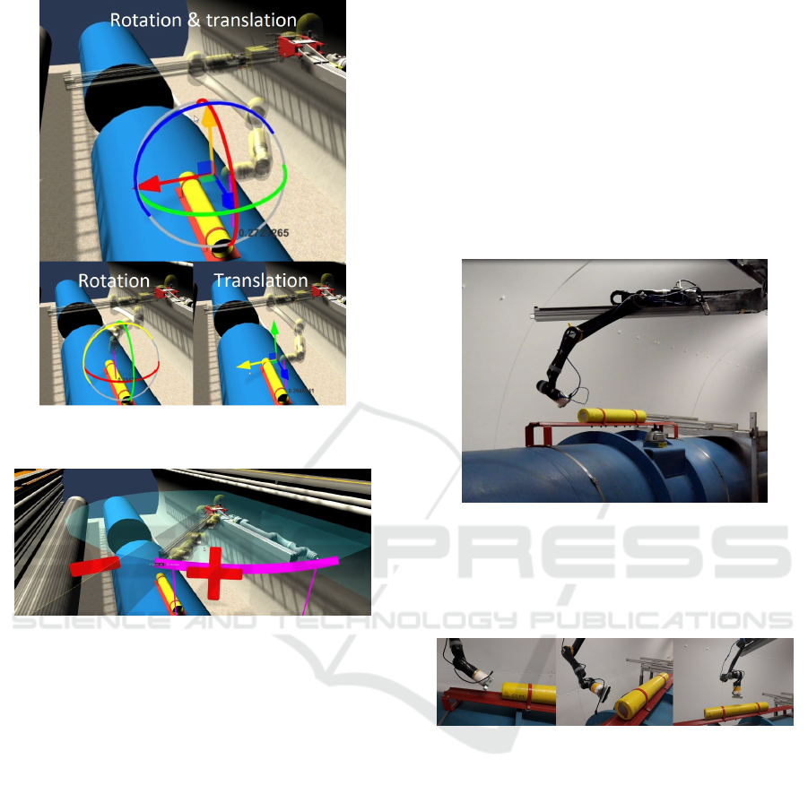
Figure 8: Inverse kinematics control with a gizmo that can
be dragged with a mouse.
Figure 9: Interactive joint position markers and controls in
the scene.
live positioning, 3D point cloud, force feedback nor
other collision detection feedback. The experiment
also tested the user’s behaviour, to see if he or she
would be focused more on the camera feedback or 3D
model, and what would be the response to small dis-
crepancies between the real robot’s position and the
position in the Virtual Reality related to the external
environment. In this paper, we focus on the use of
standard inputs such as a keyboard and a mouse to
interact with the Virtual Reality environment, as they
are readily available and universal. In both 2D and 3D
systems, the time delays are minimal and much lower
than the limit of 300 ms where the operator would
change the control strategy. This behaviour was in-
vestigated in the section ”Navigation task with time-
delay” of (Lunghi et al., 2019).
During the experiment the heart rate and the gal-
vanic skin response (GSR) of the operator were mea-
sured and recorded to see how the volatility can be
correlated with the events that occur during the op-
eration. It could be a collision, malfunction of soft-
ware or hardware, or network delays. A more difficult
position of the arm, collision vicinity or other stress
sources could also cause increased stress.
3.1 Setup
A mock-up of the LHC tunnel (Figure 10) was used
to represent a real scenario where the end effector had
to approach the BLM device (yellow cylinder). The
manipulator is installed on the TIM robot moving on
a rail attached to the ceiling. At the end of the effector
there is a camera.
Figure 10: Experiment scene.
In the experiment, the goal was to approach the
BLM in 3 different positions of the effector shown in
Figure 11 within a specified tolerance of angles with
an unrestricted pose of the rest of the manipulator.
Figure 11: Position goals (from the side, from behind and
from above).
The person used a laptop with the GUI in a sepa-
rate room isolated from the experiment scene (Figure
12). The full cycle of familiarisation training with the
GUIs, operating the arm, measurements and feedback
was performed by 4 (n = 4) people. It was a pilot
project with the small number of subjects to under-
stand if indicative results show promise in expanding
this area of research. The results can be considered as
indicative/early-stage. The subjects were aged 20-35,
they were not operating the robots before but they had
at least basic knowledge in robotics.
3.2 Workload Measurement
The user experience was assessed with the aid of the
user’s responses to the NASA Task Load Index (TLX)
ICINCO 2021 - 18th International Conference on Informatics in Control, Automation and Robotics
392
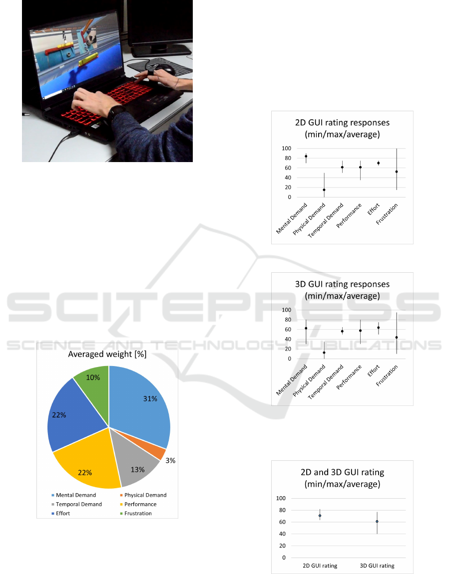
Figure 12: Operator’s local computer with the open Mixed
Reality GUI. The hearbeat and GSR sensors are worn on
hands.
workload questionnaires (Hart, 2006) and via open
feedback written at the end of the experiment. Ac-
cording to the responses, in the chart shown in Figure
13, there is a weight distribution of the elements con-
tributing to the workload. The Physical Demand has
the lowest weight as the control does not require any
other activity other than keyboard and mouse opera-
tion. The highest weight was given to Mental Demand
and its derivatives, as they played a significant role re-
garding performance and effort - which includes ad-
ditional Mental Demand.
Figure 13: Averaged weights in NASA-TLX question-
naires.
In Figures 14 and 15 the ratings of the workload
subscales with marked minimum, maximum and av-
erage values from both tests - 2D and 3D GUIs are
shown. From these values, it can be deducted that
Frustration varied significantly depending on the per-
son and the Physical Demand was low, however the
other subscales averaged around the value of 60-70.
The biggest difference between 2D and 3D GUIs was
in the Mental Demand subscale. It is possible that the
mental demand may only have been lower as the users
could choose their viewpoint in the scene, but this in-
dicates that the use of a 3D simulated environment
with flexibility of viewpoints provides a big advan-
tage to ease of teleoperation.
Figure 14: Rating responses for 2D GUI.
Figure 15: Rating responses for 3D GUI.
Overall, the workload difference between the
GUIs was 14% (61 for 3D to 71 for 2D).
Figure 16: 2D and 3D GUI ratings.
Valuable points can also be drawn from the written
feedback:
From 2D to 3D Mixed Reality Human-Robot Interface in Hazardous Robotic Interventions with the Use of Redundant Mobile Manipulator
393
• In the operation with the 2D GUI, the views from
the cameras played a big role. Because the cam-
era axis was tilted to have a view from above, it
was not easy to understand the orientation of the
end effector with respect to the stream. There was
a problem when the arm went out of the camera
frame so that the pose of the manipulator was not
visible, which sometimes made the operation very
difficult if the operator did not remember the pre-
vious joint configuration.
• Operators generally focused on the camera views
in the 2D GUI and on the model view in the 3D
GUI. The use of cameras only helped to prevent
collisions when the whole arm was visible in the
stream. However, having the model and environ-
ment in 3D made the movements much more com-
fortable, as the scene can be seen from any angle,
which according to the feedback, was the biggest
advantage of this view. On the other hand, too
much trust was put in the model, and if there were
any discrepancies between the models and the re-
ality or there was an un-modelled obstacle, there
was an increased risk of collision if the camera
streams were not checked regularly.
• The experiment focused on the use of the joint
coordinate system but, especially in approaching
the BLMs, the Cartesian coordinate system con-
trol would be more suitable and could make the
operation easier.
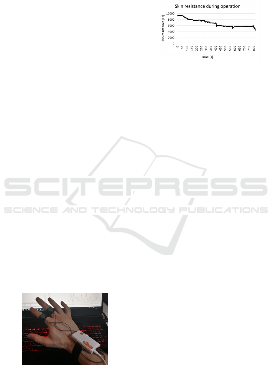
3.3 Galvanic Skin Response
Measurement
GSR sensors detect changes in the electrical skin con-
ductance caused by sweat gland activity. The mois-
ture changes the balance of ions in the fluid, which
results in measurable changes. Two electrodes were
placed on emotionally sensitive locations with high
sweat glands density. In this experiment, the sensors
were placed on fingers and the device was attached to
the wrist (Figure 17).
Figure 17: Shimmer GSR device attached on a hand.
Figure 18: Skin resistance graph.
An example skin resistance dataset recorded dur-
ing an operation is shown in the Figure 18. The
value dropped over time with a few steeper variations,
meaning that the glands activated and the conductance
increased. This response may be correlated with an
increased operator’s stress. However, it was noticed
that simply the contact with the electrodes and Vel-
cros causes minimal sweating under them. The other
parameter is the force with which the electrodes are
pressed to the skin - a higher force causes less resis-
tance. Moreover, small movements of the finger to
touch the keyboard or mouse may have provoked no-
ticeable spikes in the signals. Thus, further study is
necessary. From the observations and analysis of the
recordings, the following conclusions were drawn:
• The electrodes should be worn at least 1 hour un-
der stable conditions to stabilize sweating;
• The use of electrodes with conductive gel attached
with an adhesive to a place which does not move
may be a solution to eliminate the effects of the
motion of the fingers;
• An emotional fast response is clearly visible on
graphs for a distinctive event (i.e. unexpected be-
haviour, collision, high stress) but slowly increas-
ing stress may be harder to deduct.
3.4 Heartbeat Measurement
The stress of a person can be correlated with his or
her heart rate measured using a photoplethysmograph
(PPG) optical sensor (Mohan et al., 2016). The sensor
can be clipped on an ear lobe or be integrated in a
smart watch. In the experiment the second option was
used.
An example heart rate graph recorded during an
operation is shown in Figure 19. It is visible that
the base frequency is around 70 beats per minute
(bpm), however there were moments when the fre-
quency raised up to 100 bpm. It may be interpreted
that the person was dealing with more mental load or
breathing pattern changed due to the performed task.
In a steady state, during a typical work in front of the
computer, the heart rate doesn’t vary more than a few
ICINCO 2021 - 18th International Conference on Informatics in Control, Automation and Robotics
394
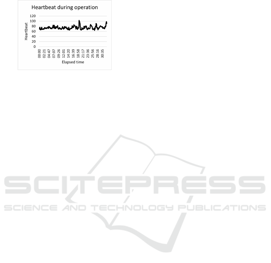
Figure 19: Heart rate graph.
beats per minute, what was checked with the same
sensor before the experiment.
4 CONCLUSIONS AND FUTURE
WORK
This paper describes how a Mixed Reality HRI can
be used in a real hazardous scenario where a redun-
dant manipulator is used via teleoperation of an op-
erator to perform an inspection taks. It presented the
robotic system’s architecture and functionalities that
were achieved. The comparison of the standard 2D
GUI and the 3D Mixed Reality GUI was made in an
experiment where the workload and operator’s bio-
metric parameters were measured. The main con-
clusion from this experiment was that the teleoper-
ation with 3D MR HRI mitigates cognitive fatigue
and stress by improving robot’s pose and scene un-
derstanding by an operator.
To allow for Cartesian control using this robot,
the pose control problem of the redundant manipula-
tor will be studied and different solutions (Jacobian-
based, heuristic) will be tested.
To increase the trust and robustness of the simu-
lated environment, real-time point cloud and environ-
ment reconstruction is an important evolution in the
Mixed Reality control. Future work will be dedicated
to integrate these functionalities.
As the 3D environment has been rendered on a
2D screen, the immersion and experience of the user
is much better with larger screens. A bigger scene im-
mersion may be achieved with the use of a VR head-
set and/or different input devices, which could also be
controlled with gestures or VR controllers. However,
it requires more preparation and setup from the oper-
ator in a real intervention where the access time in the
area may be limited. Future work will also integrate
and evaluate the effectiveness of these devices when
performing common teleoperation tasks at CERN.
Further study and tests will be done to compare
the reading with GSR measurement, heartbeat rate
and camera recordings to select the factors that clearly
impact the operator heart beat and GSR resistance. If
the effect is immediate, the values could be communi-
cated to the operator in the GUI in order to let him or
her realize about the body reaction to the performed
task.
REFERENCES
Almagro, C. V., Di Castro, M., Lunghi, G., Prades, R. M.,
Valero, P. J. S., P
´
erez, M. F., and Masi, A. (2019).
Monocular robust depth estimation vision system for
robotic tasks interventions in metallic targets. Sensors
(Switzerland), 19(14):1–28.
Almeida, L., Menezes, P., and Dias, J. (2020). Interface
Transparency Issues in Teleoperation. Applied Sci-
ences, 10(18).
Andr
´
es Mart
´
ın Barrio (2020). Design, modelling, control
and teleoperation of hyper- redundant robots. 2020.
Chacko, S. M. and Kapila, V. (2019). An Augmented Real-
ity Interface for Human-Robot Interaction in Uncon-
strained Environments. IEEE International Confer-
ence on Intelligent Robots and Systems, pages 3222–
3228.
de la Cruz, M., Casa
˜
n, G., Sanz, P., and Mar
´
ın, R. (2020).
Preliminary Work on a Virtual Reality Interface for
the Guidance of Underwater Robots. Robotics, 9(4).
Di Castro, M., Ferre, M., and Masi, A. (2018a). CERN-
TAURO: A modular architecture for robotic in-
spection and telemanipulation in harsh and Semi-
Structured environments. IEEE Access, 6:37506–
37522.
Di Castro, M., Tambutti, M. L. B., Ferre, M., Losito,
R., Lunghi, G., and Masi, A. (2018b). i-TIM: A
Robotic System for Safety, Measurements, Inspection
and Maintenance in Harsh Environments. In 2018
IEEE International Symposium on Safety, Security,
and Rescue Robotics (SSRR), pages 1–6.
Hart, S. G. (2006). Nasa-Task Load Index (NASA-TLX):
20 Years Later. In Proceedings of the human factors
and ergonomics society annual meeting, 50:904–908.
Lunghi, G., Marin, R., Castro, M. D., Masi, A., and
Sanz, P. J. (2019). Multimodal Human-Robot Inter-
face for Accessible Remote Robotic Interventions in
Hazardous Environments. IEEE Access, 7:127290–
127319.
Mohan, P. M., Nagarajan, V., and Das, S. R. (2016). Stress
measurement from wearable photoplethysmographic
sensor using heart rate variability data. In 2016 In-
ternational Conference on Communication and Signal
Processing (ICCSP), pages 1141–1144.
Veiga Almagro, C., Lunghi, G., Di Castro, M., Cen-
telles Beltran, D., Mar
´
ın Prades, R., Masi, A., and
Sanz, P. J. (2020). Cooperative and Multimodal
Capabilities Enhancement in the CERNTAURO Hu-
man–Robot Interface for Hazardous and Underwater
Scenarios. Applied Sciences, 10(17).
From 2D to 3D Mixed Reality Human-Robot Interface in Hazardous Robotic Interventions with the Use of Redundant Mobile Manipulator
395
