
Power Consumption Estimation in Model Driven Software Development
for Embedded Systems
Marco Schaarschmidt
1 a
, Michael Uelschen
1 b
and Elke Pulverm
¨
uller
2
1
Faculty of Engineering and Computer Science, University of Applied Sciences Osnabr
¨
uck, Germany
2
Software Engineering Research Group, University of Osnabr
¨
uck, Germany
Keywords:
Model-Driven Development, Embedded Systems, UML, MARTE, Power Consumption, Energy Bug.
Abstract:
Due to the resource-constrained nature of embedded systems, it is crucial to support the estimation of their
power consumption as early in the development process as possible. Non-functional requirements based on
power consumption directly impact the software design, e.g., watt-hour thresholds and expected lifetimes based
on battery capacities. Even if software affects hardware behavior directly, these types of requirements are often
overlooked by software developers because they are commonly associated with the hardware layer. Modern
trends in software engineering such as Model-Driven Development (MDD) can be used in embedded software
development to evaluate power consumption-based requirements in early design phases. However, power
consumption aspects are currently not sufficiently considered in MDD approaches. In this paper, we present a
model-driven approach using Unified Modeling Language profile extensions to model hardware components
and their power characteristics. Software models are combined with hardware models to achieve a system-wide
estimation, including peripheral devices, and to make the power-related impact in early design stages visible.
By deriving energy profiles, we provide software developers with valuable feedback, which may be used to
identify energy bugs and evaluate power consumption-related requirements. To demonstrate the potential of
our approach, we use a sensor node example to evaluate our concept and to identify its energy bugs.
1 INTRODUCTION
Through the popularity of Internet of Things (IoT)
and Industrial Internet of Things (IIoT), embedded
systems are increasingly used in domains like envi-
ronmental monitoring, smart cities, agriculture, and
smart factories (Elijah et al., 2018; Abd El-Mawla
et al., 2019; Zanella et al., 2014). According to (Gupta
et al., 2017), the number of IoT-connected devices will
reach 43 billion by the year 2023, which will represent
50 percent of all networked devices (Cisco Systems,
2020). The expected standby energy consumption of
all IoT-connected devices will reach 46 TWh in 2025
(Friedli et al., 2016). As a result, non-functional re-
quirements (NFRs) based on power consumption are
gaining importance. This is especially true for battery-
powered devices that are placed at inaccessible places
(e.g., underground) (Vuran et al., 2018) or devices that
do not have any energy harvesting capabilities. Due to
the increasing complexity of algorithms and the size of
a
https://orcid.org/0000-0001-8260-5326
b
https://orcid.org/0000-0002-0841-6954
use cases, software applications of embedded systems
are becoming more complex. Moreover, the variety
of peripheral devices, processor architectures, operat-
ing systems, and communication interfaces leads to
additional challenges in software development. Fur-
thermore, the detection of so-called energy bugs is an-
other important challenge for software developers in
the field of embedded software development. In gen-
eral, an energy bug (Banerjee et al., 2014) can be de-
fined as a behavior of the complete system that causes
an unexpected energy drain, which is not necessary to
perform the actual functionality of the system. Typi-
cal energy bugs are caused by complex interactions
between software and hardware components, periph-
eral misusage, incorrect use of APIs and drivers, flaws
in the software design (e.g., preventing the system
from entering a lower power state), and unoptimized
or faulty source code (e.g., heavy usage of avoidable
wait cycles) (Banerjee et al., 2014; Pathak et al., 2011).
In contrast to conventional software bugs, energy bugs
do not necessarily lead to misbehavior of the software
itself and are not detectable without accurate simula-
tions in early stages or detailed power consumption
Schaarschmidt, M., Uelschen, M. and Pulvermüller, E.
Power Consumption Estimation in Model Driven Software Development for Embedded Systems.
DOI: 10.5220/0010522700470058
In Proceedings of the 16th International Conference on Software Technologies (ICSOFT 2021), pages 47-58
ISBN: 978-989-758-523-4
Copyright
c
2021 by SCITEPRESS – Science and Technology Publications, Lda. All rights reserved
47
measurements while the application is executed on a
fully functional hardware platform in a laboratory set-
ting. Because field or burn-in tests are not able to de-
tect such application-based misbehavior (Silicon Labs,
2010), energy bugs have to be addressed during the
early development stages.
For battery-powered devices, the energy consump-
tion of software applications can be a significant bot-
tleneck (Banerjee et al., 2016) and can cause up to
80 percent of the total energy consumption through
software-hardware interactions (Georgiou et al., 2018).
Software developers are often unaware of the impact
of software on energy consumption (Pang et al., 2016)
and it is therefore essential that NFRs related to power
consumption are considered in early design phases,
where changes are more effective (Tan et al., 2003).
In the current software development of embedded sys-
tems, a power consumption analysis is typically car-
ried out at the end of the development process. As a
result, the potentially required re-design and optimiza-
tion phases can result in time delays and increasing
costs. Additionally, there exists no approach or tool
support for a power estimation in early design phases,
where the hardware platform may not be available or
defined yet.
Model-Driven Development (MDD) is a widely
accepted paradigm improving the correctness and effi-
ciency in software engineering used both in research
and industry (Domingo et al., 2020). By using mul-
tiple levels of abstraction, the overall complexity of
software applications may be reduced to its essential
complexity. With automatic software code generation
processes, the quality of software applications can be
increased. Since models are not bound to the under-
lying implementation by definition, they may help to
overcome the aforementioned challenges during soft-
ware development when different hardware architec-
tures are used. If a specific software application is
supposed to run on different hardware architectures,
code adaptations for each target platform are neces-
sary. With MDD, code generators can be used that
can transform software models into source code for
the specific target platform. In software development,
the Unified Modeling Language (UML) (Object Man-
agement Group, 2017) is typically used to describe
aspects like the general structure and behavior of the
software application. Focusing on time behavior and
schedulability, the Modeling and Analysis of Real-
time and Embedded systems (MARTE) profile (Object
Management Group, 2019a) extends UML to describe
non-functional properties (NFP) of hardware and soft-
ware and provides power consumption and dissipation
modeling in a simplified way. However, the provided
stereotypes are not sufficient to model dynamic power
consumption and power-related behavior in a granu-
lar way. Additionally, to the best of our knowledge,
there exists no approach to link the software applica-
tion model with hardware behavior models to obtain
an early, rapid and straightforward power consumption
estimation of a software application for given hard-
ware configurations. To address the gap of power con-
sumption estimation in MDD, we present the follow-
ing, novel contributions in this paper:
•
We address the gap between software and hard-
ware modeling by describing hardware compo-
nents with UML behavioral models. By linking
these models, the impact of the software applica-
tion on hardware components is made explicitly
visible. Furthermore, by including the microcon-
troller, sensors, actuators, and communication in-
terfaces, a system-wide power estimation can be
achieved.
•
We provide a UML-based power analysis profile
to model power-related NFPs of hardware compo-
nents. Our profile extends MARTE for a more fine-
grained and dynamic characterization of hardware
behavior when used from a software perspective.
•
We propose a lightweight interchange format of
hardware component models and power character-
istics that enables Model-2-Model (M2M) transfor-
mations across development and analysis tools.
•
Finally, we propose a workflow for software de-
velopers that describes the integration of our ap-
proach into the MDD process.
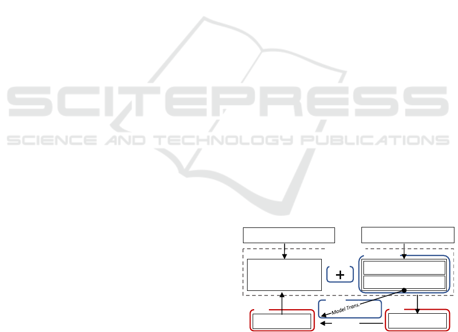
The general methodology of our proposed approach
is shown in Figure 1. The approach aims to combine
software models with hardware models to achieve an
early estimation by using the concepts of MDD for
power consumption analysis. We are using hardware
Software Application
Model
Hardware Models
Power Description
Simulation
Power Analysis
Hardware Properties
Test Cases
Trace Data
Optimization
Application Requirements
Sec. 2.3
System Model
Sec. 2.1 & 2.2
Sec. 3
Sec. 3
Sec. 2.4
Figure 1: Overview and methodology of our approach.
properties to derive hardware models and extend those
models with power consumption aspects. For every
relevant hardware component from the software per-
spective, e.g., microcontroller, sensors, and actuators,
a separate hardware model is defined. Thus, our ap-
proach provides a system-wide view and is not limited
ICSOFT 2021 - 16th International Conference on Software Technologies
48

to a specific group of hardware components. By us-
ing UML to describe hardware models, we are able to
combine the software and hardware domain, which we
define as a system model (c.f. Figure 1). The resulting
model is completely integrated into the software do-
main and may be used to derive energy profiles when
simulated. An energy profile describes the effect of the
software application on power consumption over time
for an embedded system when used with specific hard-
ware components. This is an important step towards an
energy transparent software application. By providing
detailed feedback, the concept of energy transparency
(Georgiou et al., 2018) allows software developers to
make energy-aware decisions in order to meet power
consumption requirements. Software developers may
use energy profiles to visualize the energy-related im-
pact of software applications, design changes, and al-
gorithms. Moreover, energy profiles may be used to
identify energy bugs and evaluate power consumption-
based NFRs.
The remainder of this paper is organized as fol-
lows: Section 2 describes our approach, which is eval-
uated in Section 4 using an IoT-related use case. Sec-
tion 3 introduces the integration of our approach into
the development workflow. Related research and their
conceptual differences are discussed in Section 5. Sec-
tion 6 discusses our approach and Section 7 concludes
this paper and presents future work.
2 RESEARCH APPROACH
This section describes our research approach for a
model-based power consumption estimation of embed-
ded systems. Figure 1 provides an overview of the pro-
posed approach. It is divided into four main sections:
The process of hardware abstraction (c.f. Section 2.1)
and energy behavior modeling (c.f. Section 2.2), the
integration of hardware models (c.f. Section 2.3), and
M2M transformation (c.f. Section 2.4).
2.1 Hardware Component Modeling
A key challenge of our approach is to model the dy-
namic behavior of hardware components, extend those
models with energy-related parameters and provide an
interface to make the impact of the software applica-
tion quantifiable. As a formal notation, we denote a
hardware component model of an embedded system
developed as
H
Sys
. Each hardware component model
H
Sys
n
is represented as a tuple
H
Sys
n
= {SM
n
, OP
n
, A
n
}
,
where the elements of the tuple are finite sets defined
as:
• SM
n
represents a finite set of all states
s
, transitions
t
and events
e
of the physical hardware component,
so that
SM
n
= {s
n
, t
n
, e
n
}
. States
s
represent a list
of operations modes, transitions
t
a list of possible
changes between states in s, triggered by events e.
• OP
n
represents a finite set of operations, which
may be used by a software model, e.g., to change
the configuration and trigger transitions.
• A
n
is a set of attributes defining the inner state of
the hardware component.
Several approaches, e.g., (Martinez et al., 2015; Zhu
et al., 2014), analyze the dynamic behavior for differ-
ent system states with varying levels of power con-
sumption. As stated in (Zhou et al., 2011; Benini et al.,
2000), each hardware component of an embedded sys-
tem can be described with a set of states defining
operating modes and transitions to switch between
modes. The concept of power state machines (PSMs)
(Benini et al., 2000; Danese et al., 2016) generally de-
scribes the annotation of states and transitions with
meta-information related to power consumption. Our
approach extends PSMs by modeling dynamic power
characteristics for states and transitions depending on
the current device configuration. We also map PSMs
directly to UML behavioral state machines (BSMs)
(Object Management Group, 2017), which can be used
as a classifier behavior of UML class elements, repre-
senting hardware components. A class element
C
hw
is
therefore suitable to represent hardware models while
modeling software applications so that
C
hw
n
= H
Sys
n
when using UML. By this, software models can in-
teract with hardware representations and simulate real
hardware accesses, which is a crucial part of estimat-
ing power consumption (Georgiou et al., 2018).
2.2 Energy Behavior Modeling with the
Power Analysis Profile
While MARTE is an expressive notation for modeling
timing aspects, there exists only limited support for
power-related characteristics and no accurate descrip-
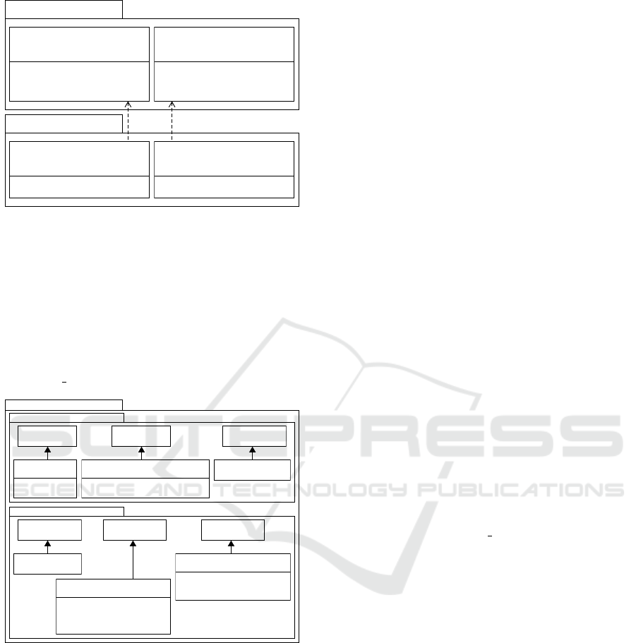
tion of voltage and electrical current. We extended
MARTE by adding those measurement units and cor-
responding NFP types as seen in Figure 2. The defi-
nition and description of the measurement units and
the NFP types follow the MARTE specification (Ob-
ject Management Group, 2019a) described in (Selic
and G
´
erard, 2014). For the ElectricCurrentUnitKind
in Figure 2, the symbol I describes the basic physical
dimensions for electric current. VoltageUnitKind con-
sists of the base dimension for mass (M), length (L),
time (T) and electric current (I). For conversions, the
baseUnit and convFactor are used. By specifying ad-
ditional data types for voltage and electric current, it is
Power Consumption Estimation in Model Driven Software Development for Embedded Systems
49
«modelLibrary»
MARTE_Library::BasicNFP_Types
«dataType»
«nfp Type»
{unitAttrib=unit}
NFP_Current
+unit: ElectricCurrentUnitKind
+precision: Real
«dataType»
«nfp Type»
{unitAttrib=unit}
NFP_Voltage
+unit: VoltageUnitKind
+precision: Real
«dimension»
ElectricCurrentUnitKind
{symbol= I}
«unit» A
«unit» mA {baseUnit=A, convFactor=1000}
«unit» uA {baseUnit=mA, convFactor=1000}
«unit» nA {baseUnit=uA, convFactor=1000}
«dimension»
VoltageUnitKind
{baseDimension= {M,L,T,I},
baseExponent = {1,2,-3,-1}}
«unit» V
«unit» mV {baseUnit=V, convFactor=1000}
«unit» uV {baseUnit=mV, convFactor=1000}
«unit» nV {baseUnit=uV, convFactor=1000}
«modelLibrary»
MARTE_Library::MeasurementUnits
Figure 2: Extended Measurement Units and NFP Data
Types.
possible to evaluate the power consumption of states
and transitions in a dynamic and granulated manner.
To be able to model and analyze dynamic power
characteristics, we define the Power Analysis Profile
(PAP), which is based on MARTE and extends the
profile by adding new tags and using the aforemen-
tioned units (e.g., VoltageUnitKind), and data types
(e.g., NFP Voltage) as shown in Figure 3. The pro-
Power Analysis Profile (PAP)
HardwareAbstraction
«Stereotype»
HWDeviceBehaviouralState
+current: NFP_Current
+hasDynamicConsumption: Boolean
+execTime: NFP_Duration
+msgSize: NFP_DataSize
«Stereotype»
HWDeviceBehaviour
«Stereotype»
HWDeviceBehaviouralTransition
+current: NFP_Current
+hasDynamicConsumption: Boolean
+execTime: NFP_Duration
«Stereotype»
HWBehaviouralImpact
«Stereotype»
HWDeviceAbstraction
+supplyVoltage: NFP_Voltage
+frequencies: Interval<NFP_Frequency>
HardwareBehaviour
«Metaclass»
Operation
«Stereotype»
HWPowerAttribute
+id: String
+value: String
«Metaclass»
Transition
«Metaclass»
State
«Metaclass»
StateMachine
«Metaclass»
Attribute
«Metaclass»
Class
Figure 3: Simplified overview of the Power Analysis Profile.
vided stereotypes are divided into two main pack-
ages HardwareAbstraction and HardwareDeviceBe-
haviour. Stereotypes provided by the HardwareAb-
straction package are specifically designed to de-
scribe abstract hardware components. UML classes
annotated with HardwareDeviceAbstraction are used
as a base representation of a hardware component
model
H
Sys
. Due to the annotation, general proper-
ties can be specified such as the supply voltage and
supported frequencies. In addition, operations and at-
tributes influencing the behavior of a hardware com-
ponent in terms of power consumption are annotated
with HWBehaviouralImpact and HWPowerAttribute
respectively. The software can use those operations to
change HWPowerAttribute annotated attributes, allow-
ing dynamic behavior changes of the hardware com-
ponent. By this, a connection between the software
model and the hardware component model is defined.
Stereotypes provided by the HardwareAbstraction
package can be used to express the power-related
behavior. Each hardware model class
C
hw
includes
a BSM defining operation modes and transitions.
The HWDeviceBehaviouralState and HWDeviceBe-
haviouralTransition stereotypes are used to extend
the BSM with power-related characteristics. For ex-
ample, a software application changes the configura-
tion (e.g., number of measurements) of a sensor dur-
ing execution. To take this kind of dynamic behavior
into account, our approach evaluates related parame-
ters whenever a state is entered or transition is exe-
cuted.
In general, the Value Specification Language
(VSL) (Object Management Group, 2019a; Selic
and G
´
erard, 2014) is used to model dynamic be-
havior. However, the basic concept was slightly
adapted to be able to express the relation be-
tween tags of states or transitions and tags and
attributes from the instance of a class. When
NFP types from the MARTE specification are
used for tagged values, they can be expressed as
a tuple
(value, expr, unit, source, precision, statQ, dir)
(Object Management Group, 2019a). In this paper,
the first three elements are used. The
value
element
contains the actual value and can be expressed as
numerical quantity or string.
expr
is an optional el-
ement and contains a VSL Expression, if an expres-
sion instead of a fixed value is used and
unit
specifies
the physical measurement unit. As basic example for
the tuple notation, the tagged value current (c.f. Fig-
ure 3) can be expressed as
(value = 1.5, unit = mA)
,
(1.5, −, mA, −, −, −, −)
or
(1.5, mA)
if the shortened
notation is used.
In related approaches (c.f. Section 5), a fixed nu-
meric term is used to describe the power, execution
time, and other tagged values within a state and a tran-
sition. Our approach presented in this paper does not
have this limitation and is able to model a dynamic
behavior by using expressions, which can be evalu-
ated dynamically during the analysis process when a
state is entered or a state transition is executed. By
modeling dynamic behavior, it is now possible to in-
clude modifiable configurations of hardware compo-
nents and to evaluate the interaction of these compo-
nents with the software application model during sim-
ulation. A typical example of a configuration is the
number of repeated measurements of a sensor before
an average value is calculated. If the configuration of a
ICSOFT 2021 - 16th International Conference on Software Technologies
50
hardware component is changed by the software appli-
cation during simulation, the power consumption for
a specific state or transition may be affected and can
be re-evaluated dynamically. A change in the behavior
can also occur if the software application varies the
amount of data to be transmitted by a communication
interface, which affects the time the hardware compo-
nent model stays in a transmission state. A dynamic
behavior can be declared by setting the value of the tag
hasDynamicConsumption = true
. If set, tagged values
based on NFP types containing an expression. In gen-
eral, the expression consists of elements from the sets
V
n
, C
n
and O
n
, where
• V
n
denotes all variables leading to a dynamic be-
havior for a given state or transition of a hardware
component.
• C
n
represents a list of constants.
• O
n
denotes a finite set of mathematical operators
to combine constants and variables.
The definition of variables in
V
n
is based on the VSL
and uses the Variables type from the VSL::Expressions
package. In our approach, the definition and usage
are slightly adapted and differ from the specification
to enable cross-references between tags of different
states and transitions as well as attributes from the
instance of a class
C
hw
to achieve a dynamic behav-
ior. First, the MARTE specification stated a method-
ological rule, that analysis tools have to compute the
VSL::Expressions::Variables and return them to the
UML model (at the start of a VSL evaluation). In our
approach, the evaluation has to be performed when-
ever the value of variables changes during simulation.
Second, the VSL::Expressions::Variables used in this
approach are not declared explicitly. Instead, we use a
specific naming scheme to achieve a linkage between
the variable definition and the tagged value or attribute
it is linked to. For the process of power consumption
optimization we defined the following schemes for
variables:
• $ tag : Denotes the tagged value for a tag in
the scope of the current state or current transition.
• $SM. NameO f State . tag :
Represents a tag of a state within the same BSM.
• $SM. NameO f Transition . tag :
Represents a tag for a transition within the same
BSM.
• $AT T R. attributeId : Denotes an attribute
of the hardware abstraction class H
Sys
annotated
with the HWPowerAttribute stereotype. The id tag
must match attributeId .
An example for a dynamic execution time (execTime)
can be expressed as
(expr = 2.0 · $ATTR.var, unit =
ms)
. If the current consumption of two states
A
and
B
are linearly dependent, the tagged value for state
B
can be expressed as
(expr = $SM.A.current ·2, unit =
mA)
. In the follwing chapters, the shortened notation
(value|expr, unit) is used for a better readability.
2.3 Combining Software & Hardware
Models
To achieve a power consumption estimation in early
design phases, software developers have to integrate
hardware models into the software model domain, al-
lowing a software model to be tested even when the
hardware platform is not fully finalized. Furthermore,
different types of hardware models can be integrated
and thus performance comparisons or design-space ex-
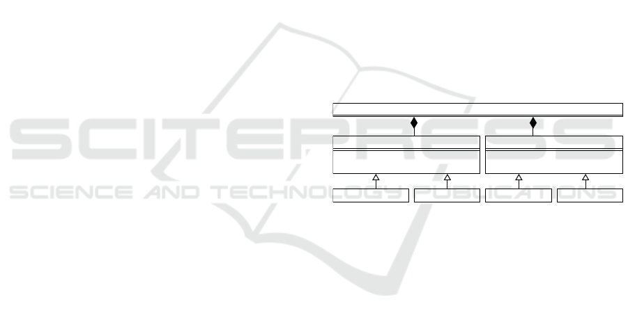
plorations (Gries, 2004) can be performed. Figure 4
shows the representation and integration of hardware
models into a software application model. The Hard-
ware Manager class in Figure 4 provides a centralized
management and monitoring of all hardware models
of a system that are essential for the software appli-
cation. Therefore, it serves as a central interface be-
tween the software and hardware models. All hard-
GenericLED
Bosch BME280
NXP LPC54114
Hardware Manager
Espressif ESP32
PeripheralDevice
+powerOff():void
+powerOn():void
ProcessingUnit
+setPowerMode(powermode:uin8_t):void
+setVoltage():void
0..n
1..n
Figure 4: Integration of abstract hardware components.
ware models are assigned to one of the two abstract
device classes (c.f. Figure 4), representing Process-
ing Units and Peripheral Devices like sensors, ac-
tors, and communication interfaces. Thereby, some
basic power-related operations are provided, which
should be implemented by a hardware model to pro-
vide an interface for the software application. Each
generalization should follow the Hardware Proxy Pat-
tern (Douglass, 2011) representing peripheral devices
in the software model domain and include an in-
terface for the software model and a state machine
to express power-related behavior. Interface descrip-
tions can be derived, e.g., from existing driver descrip-
tions. This has an advantage for the following code
generation by MDD tools because hardware models
can be replaced with driver implementations while
leaving the software application unchanged. By this,
the generated software application remains platform-
independent. The implementation of the processor is
a special challenge due to its complexity, which re-
quires further abstraction. There exists a great dif-
ference in the characteristics and number of operat-
Power Consumption Estimation in Model Driven Software Development for Embedded Systems
51
Hardware Component Model
«HWDeviceBehaviouralState»
Off
Behaviour definition
Class definition
«HWDeviceBehaviouralState»
On
«HWDeviceAbstraction» DimmableLED
- «HWPowerAttribute» brightnessLevel: int
+ «HWBehaviouralImpact» setBrightness(level:int):void
Peripheral Device
+ «HWBehaviouralImpact» powerOff():void
+ «HWBehaviouralImpact» powerOn():void
«HWDeviceBehaviouralState»
current: (0,mA)
hasDynamicConsumption: false
«HWDeviceBehaviouralState»
current: (($ATTR.brightness/100)*5,mA)
hasDynamicConsumption: true
«HWPowerAttribute»
id = brightness
value = uniform (0:int,100:int)
tunOnEvent()
turnOffEvent()
Figure 5: Basic example of the applied research approach.
ing modes of processors. For example, each proces-
sor family has a different number of operating modes
and implements a different procedure for powering
the flash, SRAM banks, or oscillators in individual
operating modes. To be able to provide a consis-
tent interface for the software model, the abstract
class ProcessingUnit provides a set of predefined
PowerModes = {ACT IV E, SLEEP, DEEP SLEEP,
DEEP POW ER DOW N, OFF}
which has to be
mapped to the existing power modes of the specific
microcontroller. When the software application has
to be generated for different processor architectures, a
hardware abstraction layer (HAL) approach has to be
implemented and linked before the compilation.
Figure 5 shows a basic hardware model example of
a DimmableLED using the aforementioned concepts
and techniques. The class definition (c.f. the upper part
of Figure 5) is derived from the base class Peripheral
Device (c.f. Figure 4) and is extended by adding an in-
ternal attribute brightnessLevel, describing the current
brightness of the LED as well as a method to change
the attribute by the software model. The stereotype
HWDeviceAbstraction is used to set a unique id as well
as a specification about the value range. For example,
this property may be used by simulation environments
when return values from sensors or radio interfaces
have to be generated. When the functions powerOff()
and powerOn() are called, events are emitted initiating
state transitions. The behavior is represented by a state
machine (lower part of Figure 5). The state machine
consists of two states Off and On, which are extended
with the HWDeviceBehaviouralState stereotype from
the PAP. The tagged value of the current tag in the
state Off is set to a fixed value, while an expression
is used to define a dynamic current consumption in
the state On. Depending on the attribute brightness
of the DimmableLED class, the current consumption
can vary between 0.05 mA and 5 mA. If the software
model changes the brightness level during simulation,
the tagged value will be updated with the new value.
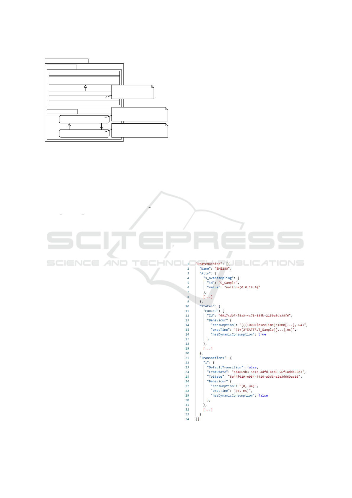
2.4 Model-2-Model Interchange Format
M2M transformations are an important aspect of
MDD. In our approach, a M2M transformation of hard-
ware component models is used along with trace anal-
ysis to perform a power consumption estimation with
external tools like MATLAB (The MathWorks, Inc.,
2021). We provide a lightweight JSON-based (Nur-
seitov et al., 2009) interchange format for Meta Object
Facility (MOF) (Object Management Group, 2019b)
based models, which are annotated with our PAP. Dur-
ing the creation of the JSON-based description, all
UML model elements are processed and searched for
PAP annotations. Beside the basic structure of state
machines (e.g. states and transitions), power-related
tagged values and class attributes (e.g., names, data
types, ranges) are also transformed to take the dy-
namic behavior into account. This information is sub-
sequently stored in a JSON file. External tools like
MATLAB can import the hardware component model
descriptions to be aware of the energy-related dynamic
behavior as well as the expected power consumption
based on the actual hardware states. After the sim-
ulation, traces can be used for the power consump-
tion estimation process. The M2M approach is part
of the proof of concept for the analysis process based
on models annotated with PAP. Figure 6 shows a ba-
sic example of the JSON-based description containing
multiple states, transitions, and class attributes.
Figure 6: Basic example of a JSON based BSM description.
ICSOFT 2021 - 16th International Conference on Software Technologies
52
3 EVALUATION
In this section, we evaluate our approach using the
methodology described in Figure 1 (introduced in Sec-
tion 1) to obtain an energy profile of a software appli-
cation for a sensor node in an early design phase. We
use IBM Rational Rhapsody 8.4 (IBM, 2021) as an
MDD tool and simulation environment for software
and hardware models. To evaluate the system in terms
Embedded System Board
LPC54114
MCU
LED
Bosch BME280
Figure 7: Hardware components used for this use case.
of power consumption, we define an exemplary hard-
ware platform using an NXP LPC54114 low-power
microcontroller (NXP Semiconductors, 2019) and two
peripheral devices, as shown in Figure 7. The NXP
LPC54114 is based on an ARM Cortex-M4 and also
includes an ARM Cortex-M0+ co-processor, which
has been disabled for this use case. The first peripheral
device is a Bosch BME280 (Bosch Sensortec GmbH,
2018) environmental sensor for measuring tempera-
ture, barometric pressure, and humidity. A LED as a
second peripheral device is used as a visual output.
All hardware models are derived from the correspond-
ing data sheets (c.f. (Bosch Sensortec GmbH, 2018),
(NXP Semiconductors, 2019)). The behavior of the
LED can be described with two basic states On and
Off, annotated with a static current of 10 mA for the
state On and 0 mA for the state Off. The behavior of
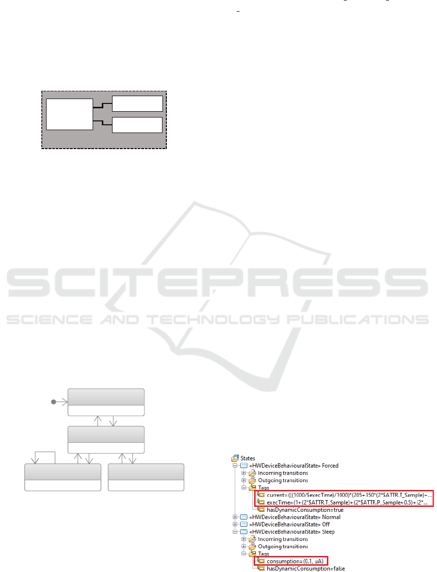
the BME280 is more complex, resulting in a more ex-
tensive BSM as shown in Figure 8. When powered,
Off
«HWDeviceBehaviouralState»
Sleep
«HWDeviceBehaviouralState»
Normal
«HWDeviceBehaviouralState»
Forced
«HWDeviceBehaviouralState»
Figure 8: BSM of the Bosch BME280.
the sensor is operating in the mode Sleep. The sensor
can be dynamically configured to take a single mea-
surement (Mode: Forced) or to continuously take mea-
surements (Mode: Normal). The oversampling rate
for each sensor (e.g., temperature, pressure, humid-
ity) can be configured individually. Therefore, an at-
tribute for each sensor was added to the class definition
of the BMW280 using the HWPowerAttribute stereo-
type, while using the names T Sample, P Sample, and
H Sample respectively as tagged values for the tag id.
Additionally, another attribute denoting the interval be-
tween measurements in Normal mode has been added.
A software application may dynamically configure
the oversampling rate of each sensor (e.g., tempera-
ture, pressure, humidity) individually, influencing the
amount of electric current and the measurement time.
To address this, the tag id of the attributes are refer-
enced in the value fields of the current and execTime
tags from stereotypes provided by the HardwareBe-
haviour package. Figure 9 shows the usage of such
references in a more complex example for the state
Forced. The amount of electric current, as well as the
execution time for this state, depends on the current
configuration of the sensor. It is important to notice,
that a change in one of the defined attributes annotated
with the HWPowerAttribute stereotype will influence
the amount of electric current and the execution time
for the state as shown in Figure 9. As a realization of
the Hardware Proxy Pattern for the software-hardware
interaction between the BME280 hardware model and
the software application model, we abstracted the ex-
isting API definition (Bosch Sensortec GmbH, 2021)
and applied the HWBehaviouralImpact stereotype on
each operation affecting the power-related behavior.
The state machine of the LPC54114 is shown in Fig-
ure 10. The tagged values for current in each state of
the microcontroller are static and taken from direct
measurements and data sheets. Since the execution
of the software application is responsible for all state
changes, the tag execution time is left empty and is not
needed. In this scenario only the state Active and Sleep
are used. For those states, the current is set to 9.9 mA
and 3 mA respectively. We implement an executable
software application model, as shown in Figure 11. As
a typical use case for smaller IoT systems, a software
implementation was defined, measuring and evaluat-
ing temperature values. The implementation consists
of a single class containing a BSM with four different
working states. The four defined states of the BSM
Figure 9: BME280 with annotations in Rational Rhapsody.
Power Consumption Estimation in Model Driven Software Development for Embedded Systems
53
Active
«HWDeviceBehaviouralState»
Sleep
«HWDeviceBehaviouralState»
Deep_Sleep
«HWDeviceBehaviouralState»
Power_Down
«HWDeviceBehaviouralState»
Deep_Power_Down
«HWDeviceBehaviouralState»
Figure 10: BSM of the NXP LPC54114.
describe the following actions:
•
Input: Represents the part of the software ap-
plication where a single measurement with the
BME280 (Forced mode) is performed.
•
Process: In this state, the measurement is pro-
cessed. If a threshold is exceeded, the application
will change to the Output state and to Sleep other-
wise.
•
Output: In this state, the LED will be enabled as
a visual output and the system will switch to the
Sleep state afterwards.
•
Sleep: Denotes the state in which the LPC54114 is
set to a low power mode for a fixed amount of time
before re-entering the Input state automatically.
Input Process
evNewData
Output
evSetOutput
Sleep
evSleep
evOutputCompleted
evWakeUp
Figure 11: Software Model.
As preparation for the simulation, a measurement se-
ries with BME280 was performed. The measured val-
ues are passed back to the software model when the
hardware model of the sensor is queried. During the
simulation, trace logs of software-hardware interac-
tions and hardware model state changes were recorded
and used along with a M2M transformation of the hard-
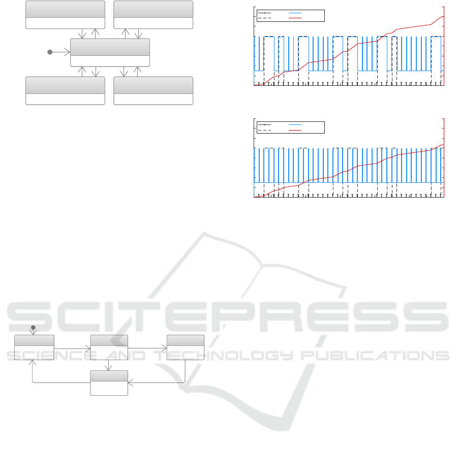
ware models for a trace analysis in MATLAB. Fig-
ure 12 presents the resulting energy profiles of the
software application model interacting with the de-
fined hardware components models in two different
scenarios. The power estimation and accumulated en-
ergy consumption in the upper part of Figure 12 de-
scribes a scenario containing an energy bug preventing
the NXP LPC54114 to enter a lower power state while
the LED is turned on because of a bug in the tran-
sition between the Output and the Sleep state of the
software application model (c.f. Figure 11). The lower
part of Figure 12 describes the energy profile after the
0 20 40 60 80 100 120 140 160 180 200 220
Time (s)
0
2
4
6
8
10
12
14
16
Current (mA)
0
1
2
3
4
5
6
7
8
Cumulated Energy Consumption (Ws)
Power Estimation - Application with Energy Bug
BME280
LED
LPC54114
Total Power
0 20 40 60 80 100 120 140 160 180 200 220
Time (s)
0
2
4
6
8
10
12
14
16
Current (mA)
0
1
2
3
4
5
6
7
8
Cumulated Energy Consumption (Ws)
Power Estimation - Bug Free Application
BME280
LED
LPC54114
Total Power
Figure 12: Analysis of the behavior with MATLAB.
software developer fixed the energy bug (e.g. optimiza-
tion of the software model) and re-runs the simulation.
In this example, the simulation was executed for a to-
tal of 220 seconds. The total consumption could be
reduced from approx. 6.99 Ws to 5.38 Ws after the en-
ergy bug has been fixed. In general, it is advisable to
use energy design patterns during the development of
the software application (Schaarschmidt et al., 2020).
Our approach may also be used to evaluate the impact
of such design patterns on the entire system. This il-
lustrates that our approach is able to analyze software-
hardware interactions, optimize software applications,
and evaluate power consumption-based NFRs like the
duration until an energy source may be exhausted. The
presented approach can also be used to evaluate sub-
systems related to both, hardware and software to eval-
uate individual program sequences or test cases.
4 DEVELOPMENT WORKFLOW
While the previous section evaluates our approach
with an IoT-related use case, this section discusses a
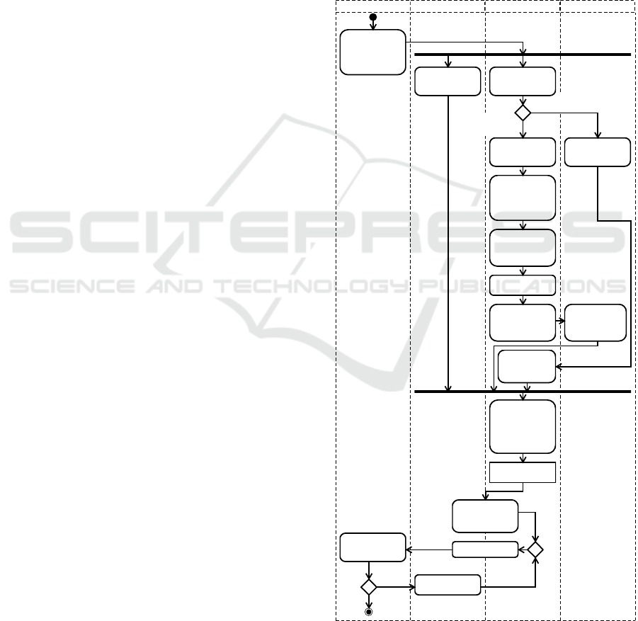
corresponding integration of the approach into a MDD
development workflow. Figure 13 shows a UML activ-
ity diagram of the proposed workflow.
In the first step, a requirement list is used to define
functional and non-functional requirements of the soft-
ware application model. Alongside the development of
the software application model in step 2, relevant hard-
ware components are identified by the software devel-
oper (step 3). Only those hardware components are
taken into account that can be directly influenced by
the software model, e.g., sensors, actuators, communi-
ICSOFT 2021 - 16th International Conference on Software Technologies
54
cation interfaces, and microcontrollers. The software
developer may use a model library from an internal
or external, private or community-driven service pro-
viding hardware component model descriptions based
on the presented M2M interchange format (c.f. Sec-
tion 2.4), which can be directly imported into modern
MDD tools, such as IBM Rational Rhapsody or En-
terprise Architect (SparxSystems, 2020). The model
library can be hosted, for example, by a centralized or-
ganization or by hardware vendors who provide driver-
s/APIs, data sheets, and hardware models as a com-
bined package.
If no hardware component model description is
available, the software developer can derive a hard-
ware model by following steps 4(a) to 4(f). The state
machine is based on the working or power modes of
the hardware component and can be derived from the
data sheet. As a next step, stereotypes from the Hard-
wareAbstraction packages of the PAP can be used to
add energy and time properties to states and transitions
(steps 4(b)-4(c)). Afterward, the UML class is defined,
which represents the interface for the software model
and contains attributes, which can be used to describe
the energy and time behavior in a precise manner. To
declare functions and attributes that affect the behavior
of hardware component models, stereotypes from the
HardwareAbstraction packages are added. In step 4(f)
the model is exported and stored in the model library.
When the modeling process of the software model
and hardware components is finalized, a M2M trans-
formation is performed. For each UML element that
has been extended with at least one stereotype pro-
vided by PAP, a corresponding trace functionality is
generated. Furthermore, a Hardware Manager is gen-
erated, so that the software model and hardware com-
ponent models can be used together in the same sim-
ulation environment of a MDD tool. The Hardware
Manager also aggregates traces for external power
analysis tools. The result is an intermediate model
which is able to provide a socket connection and trace
logs when simulated so that external power analysis
tools are able to analyze behavior changes of all hard-
ware components.
In step 7, both models are linked together by in-
cluding function calls of the hardware model class
definition in the software model. When source code
is generated, classes from hardware components can
be replaced by driver implementations. Since the func-
tion signatures of the hardware model and the driver
interfaces are identical, no code adjustments are re-
quired in the generated software application. A simula-
tion of the software application model is performed in
step 8. Afterward, the software developer may check
whether the requirements are met or optimize the soft-
ware model and repeat the simulation. The steps 4(f),
5(a), and 6 shown in Figure 13 can be executed auto-
matically. Depending on the toolchain used, the simu-
lation and analysis process can be automatized. As a
proof of concept, we implemented a plugin for IBM
Rational Rhapsody which is able to exchange hard-
ware models based on our proposed M2M interchange
format (c.f. Section. 2.4) and is also capable of gener-
ating state machines and UML classes. Furthermore,
the M2M transformation process to generate the inter-
mediate model has been automated. Both approaches
were used for the evaluation in the previous Section 4.
[maschine-readable
description available]
4(f). Store new
Hardware Model
5(b). Extend
class definitions
(optional)
4(a). Derive state
machine (power
states)
4(d). Create class
definitions
5(a). Import
Hardware Model
Descriptions
Intermediate
model
10. Optimize
software model
9. Evaluate
non-functional
requirements
6. M2M transfor-
mation: Generate
trace functionality
based on the PAP
usage
4(e). Apply
stereotypes to
attributes and
functions
4(c). Set tagged
values according
to power and time
properties
4(b).
Apply stereotypes
to state machine,
states,and tran-
sitions
7. Link Software
Model with
Hardware Models
3. Identify
relevant hardware
components
2. Model Software
Application (UML)
1. Define func-
tional and power-
related non-func-
tional require-
ments
Model Library
Hardware Model
Software Model
Requirements List
8. Simulation
[Req. not
met]
[Req. met]
[no description
available]
Figure 13: Workflow for the proposed approach.
Power Consumption Estimation in Model Driven Software Development for Embedded Systems
55

5 RELATED WORK
Concepts for modeling NFRs like power consumption
or execution time have been proposed in a set of re-
search approaches using mathematical models (Mar-
tinez et al., 2015; Bouguera et al., 2018; Zhou et al.,
2011), workflow models (Zhu et al., 2014), and Petri
nets (Andrade et al., 2010). However, they do not con-
sider the integration into software development and
MDD.
Low-level approaches such as cycle-level or
instruction-level power analyses (ILPA) are less suit-
able for evaluating software application models in
early phases since they require a high level of knowl-
edge about architectures and also have lengthy simu-
lation times (Julien et al., 2003). ILPA for example
requires assembly code for estimating the cost of each
instruction and is therefore not close to the software
model. Since these approaches are used primarily for
processor simulations, they are also not suitable for a
system-wide view that includes peripheral devices.
The authors in (Atitallah et al., 2015) provide a
power estimation solution and low-level device mod-
eling based on BSM and an extension of the IP-XACT
standard (IEEE SA, 2014) to define power-related
properties. Since their work focuses on register level
for lower-level hardware components like clock gen-
erators, it is not suitable for analysis in early design
phases in the MDD domain. Furthermore, their ap-
proach does not consider peripheral devices and their
dynamic behavior.
There exist several approaches that are using UML
and MARTE to model software and hardware aspects
for a power consumption estimation of software ap-
plications for embedded systems. In (Gomez et al.,
2012), a multi-view power modeling approach based
on UML, SysML, and MARTE is proposed to model
power aspects for different functional and structural
system views. The authors strongly focus on connec-
tions between views and do not consider a power anal-
ysis of single components nor the impact of software
applications.
In (Iyenghar and Pulvermueller, 2018), a model-
driven energy-aware timing analysis is presented,
where the design model is obtained by reverse engi-
neering and is mapped to UML classes and opera-
tions. MARTE is used to annotate the software model
with timing and power-related properties. For analy-
sis, a M2M transformation process from UML to a
timing-energy analysis model is used, where classes
are mapped to tasks and operations to runnable repre-
sentations. Since the model is derived from a reverse
engineering process, this approach is not suitable for
an analysis in early design phases. Furthermore, only
the processor instead of the complete system, includ-
ing peripheral devices, is considered.
In recent works, extensions for MARTE improv-
ing concepts for modeling and analyzing power char-
acteristics are proposed. In (Hagner et al., 2011), a
MARTE-based power consumption analysis view pro-
file is introduced, defining new stereotypes to spec-
ify power-related characteristics like the processor’s
switching capacitance or energy consumption during
the execution of tasks. Processors are annotated with
voltage and frequency parameters and tasks with the
number of cycles to find an optimal power solution
when simulating a dynamic voltage scaling.
A MARTE profile extension for dynamic power
management is proposed in (Arpinen et al., 2012). The
authors are using BSMs annotated with power speci-
fications to represent operation modes of each consid-
ered hardware component. States of hardware compo-
nents are combined to system power configurations.
As long as a configuration is active, the components
remain in their state. Use cases allocating configura-
tions are defined to generate and analyze workflows.
However, the aforementioned approaches focus on
hardware-centric views when modeling and analyzing
power consumption, while only using tasks and prede-
fined use cases to describe software aspects. By this,
those approaches barely support software developers
in the task of quantifying the influence of a software
model on power consumption. An estimation based on
abstract use cases or at task level, as suggested by the
previous approaches, is not sufficient and does not of-
fer any possibilities for software optimizations. In con-
trast, our approach is integrated into the development
process, focusing on software execution and software-
hardware interaction.
6 DISCUSSION
Our approach enables software developers to estimate
power consumption in early design phases. By linking
software application models with hardware model rep-
resentations, we are able to make software-hardware
interactions directly visible within the model. Our
novel UML-based profile enables a fine-grained and
dynamic characterization of hardware-behavior and
takes hardware-software interactions into account. A
trace analysis may be used to derive energy profiles
and identify energy bugs of software application mod-
els in early design phases. Additionally, design-space
exploration methods (Gries, 2004) may be performed
to determine the best hardware-software configuration
based on energy consumption. NFRs like total peak
power or battery capacity may be evaluated, result-
ICSOFT 2021 - 16th International Conference on Software Technologies
56

ing in design changes in the application’s workflow.
The visualization of possible energy bugs also helps
to improve the quality of the application regarding
power consumption. Our approach is tool independent
and with the lightweight interchange format, hardware
models may be exchanged between tools and reused
in different projects, which increases developer pro-
ductivity. We also presented a development workflow
describing the integration of our approach into a MDD
workflow from a software developer perspective.
Our approach also faces limitations. It is the nature
of modeling, that accuracy decreases with abstraction.
Parameters modeled with PAP are derived from data
sheets or have been previously measured in specific
environments (e.g., temperature), resulting in a loss
of accuracy. Another limitation is caused by simula-
tion environments of MDD tools where the runtime
does not match the runtime of generated code directly
executed on an embedded system. Overall, we recom-
mend our approach, as it offers valuable feedback for
developers. Additionally, an energy-related re-design
and optimization of the software application may be
performed in early design phases, reducing the overall
development time and costs.
7 CONCLUSION
In this paper, we presented an approach to estimate
the power consumption of software applications for
embedded system development in early design phases
without the need for real hardware components. Based
on MARTE, we created hardware component models
and included dynamic power characteristics in their
descriptions. Our concept offers a novel approach to
provide power estimations for software applications
in embedded system environments by considering
software-hardware interactions and making the dy-
namic power-related behavior in hardware states quan-
tifiable. During simulations, hardware accesses can be
traced, analyzed, and evaluated. Besides, our approach
may be used by software developers for the detection
of some typical energy bugs in early design phases.
The early analysis and correction of these types of
bugs lead to an improved quality of the application.
Future work includes the support for energy
sources and communication interfaces. As a power-
ful toolset for creating energy profiles and evaluating
NFR, we are also planning to provide a simulation and
analysis environment. Furthermore, we want to com-
pare our approach with physical measurements on real
hardware platforms and evaluate our approach using
more complex use cases.
REFERENCES
Abd El-Mawla, N., Badawy, M., and Arafat, H. (2019). Iot
for the failure of climate-change mitigation and adap-
tation and iiot as a future solution. World Journal of
Environmental Engineering, 6(1):7–16.
Andrade, E., Maciel, P., Falc
˜
ao, T., Nogueira, B., Araujo, C.,
and Callou, G. (2010). Performance and energy con-
sumption estimation for commercial off-the-shelf com-
ponent system design. Innovations in Systems and
Software Engineering, 6(1-2):107–114.
Arpinen, T., Salminen, E., H
¨
am
¨
al
¨
ainen, T. D., and
H
¨
annik
¨
ainen, M. (2012). Marte profile extension for
modeling dynamic power management of embedded
systems. J. Syst. Archit., 58(5):209–219.
Atitallah, Y. B., Mottin, J., Hili, N., Ducroux, T., and Godet-
Bar, G. (2015). A power consumption estimation ap-
proach for embedded software design using trace anal-
ysis. In 2015 41st Euromicro Conference on Soft-
ware Engineering and Advanced Applications (SEAA),
pages 61–68, Piscataway, NJ. IEEE.
Banerjee, A., Chattopadhyay, S., and Roychoudhury, A.
(2016). On testing embedded software. In Advances
in Computers, volume 101, pages 121–153. Elsevier.
Banerjee, A., Chong, L. K., Chattopadhyay, S., and Roy-
choudhury, A. (2014). Detecting energy bugs and
hotspots in mobile apps. FSE 2014, page 588–598,
New York, NY, USA. Association for Computing Ma-
chinery.
Benini, L., Bogliolo, A., and de Micheli, G. (2000). A survey
of design techniques for system-level dynamic power
management. IEEE Transactions on Very Large Scale
Integration (VLSI) Systems, 8(3):299–316.
Bosch Sensortec GmbH (2018). BME280 – Data
sheet, Version 1.6. Document Number BST-
BME280-DS002-15 (https://www.bosch-sensortec.
com/media/boschsensortec/downloads/datasheets/
bst-bme280-ds002.pdf).
Bosch Sensortec GmbH (2021). Github: BME280
sensor API. https://github.com/BoschSensortec/
BME280 driver. Accessed: 12.02.2021.
Bouguera, T., Diouris, J.-F., Chaillout, J.-J., Jaouadi, R., and
Andrieux, G. (2018). Energy consumption model for
sensor nodes based on lora and lorawan. Sensors,
18(7):2104.
Cisco Systems (2020). Cisco annual internet re-
port (2018–2023). White Paper C11-741490-01
(https://www.cisco.com/c/en/us/solutions/collateral/
executive-perspectives/annual-internet-report/
white-paper-c11-741490.html).
Danese, A., Pravadelli, G., and Zandon
`
a, I. (2016). Au-
tomatic generation of power state machines through
dynamic mining of temporal assertions. In 2016 De-
sign, Automation Test in Europe Conference Exhibition
(DATE), pages 606–611.
Domingo,
´
A., Echeverr
´
ıa, J., Pastor,
´
O., and Cetina, C.
(2020). Evaluating the benefits of model-driven devel-
opment. In Dustdar, S., Yu, E., Salinesi, C., Rieu, D.,
and Pant, V., editors, Advanced Information Systems
Power Consumption Estimation in Model Driven Software Development for Embedded Systems
57

Engineering, pages 353–367, Cham. Springer Interna-
tional Publishing.
Douglass, B. P. (2011). Design patterns for embedded sys-
tems in C: An embedded software engineering toolkit.
Newnes/Elsevier, Oxford and Burlington, MA.
Elijah, O., Rahman, T. A., Orikumhi, I., Leow, C. Y., and
Hindia, M. N. (2018). An overview of internet of
things (iot) and data analytics in agriculture: Bene-
fits and challenges. IEEE Internet of Things Journal,
5(5):3758–3773.
Friedli, M., Kaufmann, L., Paganini, F., and Kyburz, R.
(2016). Energy efficiency of the internet of things:
Technology and energy assessment report prepared for
iea 4e edna.
Georgiou, K., Xavier-de Souza, S., and Eder, K. (2018). The
iot energy challenge: A software perspective. IEEE
Embedded Systems Letters, 10(3):53–56.
Gomez, C., DeAntoni, J., and Mallet, F. (2012). Multi-view
power modeling based on uml, marte and sysml. In
Cortellessa, V., editor, 38th EUROMICRO Conference
on Software Engineering and Advanced Applications
(SEAA), 2012, pages 17–20, Piscataway, NJ. IEEE.
Gries, M. (2004). Methods for evaluating and covering the
design space during early design development. Integr.
VLSI J., 38(2):131–183.
Gupta, A., Tsai, T., Rueb, D., Yamaji, M., and Middleton,
P. (2017). Forecast: Internet of things: Endpoints and
associated services, worldwide, 2017.
Hagner, M., Aniculaesei, A., and Goltz, U. (2011). Uml-
based analysis of power consumption for real-time em-
bedded systems. In 2011IEEE 10th International Con-
ference on Trust, Security and Privacy in Computing
and Communications, pages 1196–1201. IEEE.
IBM (2021). Rational Rhapsody Developer.
https://www.ibm.com/products/uml-tools. Accessed:
12.02.2021.
IEEE SA (2014). IEEE Standard for IP-XACT, Standard
Structure for Packaging, Integrating, and Reusing IP
within Tool Flows. Document Number IEEE 1685-
2014 (https://standards.ieee.org/standard/1685-2014.
html).
Iyenghar, P. and Pulvermueller, E. (2018). A model-driven
workflow for energy-aware scheduling analysis of iot-
enabled use cases. IEEE Internet of Things Journal,
5(6):4914–4925.
Julien, N., Laurent, J., Senn, E., and Martin, E. (2003). Power
consumption modeling and characterization of the ti
c6201. IEEE Micro, 23(5):40–49.
Martinez, B., Monton, M., Vilajosana, I., and Prades, J. D.
(2015). The power of models: Modeling power con-
sumption for iot devices. IEEE Sensors Journal,
15(10):5777–5789.
Nurseitov, N., Paulson, M., Reynolds, R., and Izurieta, C.
(2009). Comparison of json and xml data interchange
formats: a case study. Caine, 9:157–162.
NXP Semiconductors (2019). LPC5411x - Product data
sheet, Rev. 2.5. Document identifier LPC5411x (https:
//www.nxp.com/docs/en/data-sheet/LPC5411X.pdf).
Object Management Group (2017). Unified Modeling
Language, Version 2.5.1. OMG Document Number
formal/17-12-05 (https://www.omg.org/spec/UML/2.
5.1/).
Object Management Group (2019a). A UML Profile for
MARTE: Modeling and Analysis of Real-Time and
Embedded Systems, Version 1.2. OMG Document
Number formal/19-04-01 (https://www.omg.org/spec/
MARTE/1.2/).
Object Management Group (2019b). Meta Object Facility,
Version 2.5.1. OMG Document Number formal/19-10-
01 (https://www.omg.org/spec/MOF/2.5.1/).
Pang, C., Hindle, A., Adams, B., and Hassan, A. E. (2016).
What do programmers know about software energy
consumption? IEEE Software, 33(3):83–89.
Pathak, A., Hu, Y. C., and Zhang, M. (2011). Bootstrapping
energy debugging on smartphones: A first look at en-
ergy bugs in mobile devices. HotNets-X, New York,
NY, USA. Association for Computing Machinery.
Schaarschmidt, M., Uelschen, M., Pulverm
¨
uller, E., and
Westerkamp, C. (2020). Framework of software de-
sign patterns for energy-aware embedded systems. In
Proceedings of the 15th International Conference on
Evaluation of Novel Approaches to Software Engineer-
ing - Volume 1: ENASE, pages 62–73.
Selic, B. and G
´
erard, S. (2014). Modeling and analysis
of real-time and embedded systems with UML and
MARTE: Developing cyber-physical systems. Morgan
Kaufmann, Waltham, MA.
Silicon Labs (2010). Energy debugging tools for embedded
applications. Technical report.
SparxSystems (2020). Enterprise architect tool.
https://sparxsystems.com/products/ea/index.html.
Accessed: 12.02.2020.
Tan, T. K., Raghunathan, A., and Jha, N. K. (2003). Soft-
ware architectural transformations: a new approach to
low energy embedded software. In Design, Automa-
tion, and Test in Europe Conference and Exhibition,
pages 1046–1051, Los Alamitos, CA. IEEE Computer
Society.
The MathWorks, Inc. (2021). MATLAB.
https://www.mathworks.com/products/matlab. Ac-
cessed: 12.02.2021.
Vuran, M. C., Salam, A., Wong, R., and Irmak, S. (2018).
Internet of underground things in precision agricul-
ture: Architecture and technology aspects. Ad Hoc
Networks, 81:160–173.
Zanella, A., Bui, N., Castellani, A., Vangelista, L., and Zorzi,
M. (2014). Internet of things for smart cities. IEEE
Internet of Things journal, 1(1):22–32.
Zhou, H.-Y., Luo, D.-Y., Gao, Y., and Zuo, D.-C. (2011).
Modeling of node energy consumption for wireless
sensor networks. Wireless Sensor Network, 03(01):18–
23.
Zhu, Z., Olutunde Oyadiji, S., and He, H. (2014). En-
ergy awareness workflow model for wireless sensor
nodes. Wireless Communications and Mobile Comput-
ing, 14(17):1583–1600.
ICSOFT 2021 - 16th International Conference on Software Technologies
58
