
Designing Operational Safety Procedures for UAV According to NATO
Architecture Framework
Wojciech Stecz
1,2 a
and Piotr Kowaleczko
2,3 b
1
Faculty of Cybernetics, Military University of Technology, Warsaw, Poland
2
C4ISR Software Department, PIT-RADWAR, Warsaw, Poland
3
PIKO Systems, Warsaw, Poland
Keywords:
UAV, Software Architecture, NAF, Operational Safety Procedures, Mission Control Unit, UML, SysML.
Abstract:
The article presents the principles of designing unmanned aerial platforms, which belong to the group of near
real-time systems. The correct and legally compliant design process of such systems requires adherence to
the principles of designing operational safety procedures for UAVs in accordance with the NATO Architecture
Framework. The NAF-compliant approach presented in the article enables meeting the requirements for the
certification of flying systems in accordance with the guidelines DO-178 and DO-254, which are the basic
documents on the basis of which the airworthiness of the system is assessed. The article presents the most
important stages of designing unmanned systems that were used in a military project. An example of a system
modeling method in UML and its extension, which is SysML, was also presented.
1 INTRODUCTION
In the last decade, unmanned aerial vehicles (UAVs)
have become a branch of technology experiencing one
of the greatest technological advances. The progres-
sive miniaturization of hardware platforms, the suc-
cessive increase in their computing capabilities, the
fall in component prices and increased availability of
advanced sensors, as well as the development of ar-
tificial intelligence algorithms (Stecz and Gromada,
2020a) have made all kinds of unmanned mobile plat-
forms evolve into a phase of completely autonomous
miniature devices capable of analyzing the surround-
ing environment. UAVs have contributed to the revo-
lution in many areas of life, from defense and econ-
omy to entertainment and sports. They are used to lo-
cate and to neutralize military and civil targets (Beard
et al., 2006), (Stecz and Gromada, 2020b), (Quigley
et al., 2005), detect fires (Yuan et al., 2015) or places
of illegal border crossing (Dufrene, 2005), terrain
mapping (Iscold et al., 2010), monitoring the secu-
rity of facilities (Dustin, 2015), as well as to record
images of sports and cultural events (Mademlis et al.,
2019) or simply for entertainment purposes (Nekov
´
a
ˇ
r,
2019).
a
https://orcid.org/0000-0002-5353-5362
b
https://orcid.org/0000-0002-9043-9281
UAV architecture has been described in many pre-
vious publications. Sanchez-Lopez et al. (Sanchez-
Lopez et al., 2016) presents a universal architec-
ture enabling easy adjustment of designed platform’s
functions through the selection and integration of ap-
propriate, proposed system modules. A similar, uni-
versal system architecture for unmanned aerial vehi-
cles is described in (Kekec et al., 2013). Pastor (Pas-
tor et al., 2007) presents the approach which assumes
a subscription of specific services by individual mod-
ules of mission computer. The mission computer is
the main unit that supervises the execution of the un-
manned platform mission, especially in the event of
a loss of the data link with the Ground Control Sta-
tion. The mission computer operates together with
the Flight Management System (FMS) which is re-
sponsible for a direct control of the platform. The
mission computer architecture designed for the great-
est possible capabilities of the UAV in the domain of
autonomy and control logic was presented by Gunetti
(Gunetti et al., 2013). Similar issues were also dealt
with in the works described in (Karim and Heinze,
2005a), (L
´
opez et al., 2007) and (Karim and Heinze,
2005b).
The use of interchangeable elements of the UAV
architecture is part of the concept of building plat-
forms compatible with the so-called open architec-
ture. In the coming years, such architecture will
Stecz, W. and Kowaleczko, P.
Designing Operational Safety Procedures for UAV According to NATO Architecture Framework.
DOI: 10.5220/0010516501350142
In Proceedings of the 16th International Conference on Software Technologies (ICSOFT 2021), pages 135-142
ISBN: 978-989-758-523-4
Copyright
c
2021 by SCITEPRESS – Science and Technology Publications, Lda. All rights reserved
135
dominate both civil and military systems. The in-
creased intensity of flights of unmanned platforms
as well as the use of commonly available computers
requires greater supervision over the designed algo-
rithms. Therefore, standards have been introduced
in the EU to define rules for the design and testing
of air platform architectures. For these architectures,
methodologies describing the way of designing indi-
vidual functions must also be defined. According to
the authors, the NAF methodology will be one of such
project approaches. Introduced standards, such as
(RTCA SC-205, 2011), define requirements for sys-
tem designers. The NAF methodology supports IT
system designers in the process of building software
that will be compliant with the imposed standards and
the testing process will be simplified.
2 UAV MISSION MODULE
SOFTWARE DESIGN
The chapter presents the methodology used by au-
thors in the project of building an unmanned aerial
vehicle. The examples presented later in this article
will be described in the UML language or its SysML
extension.
2.1 NATO Architecture Framework
Version 4
NATO Architecture Framework (NAF) is a standard
that enables the methodical design, implementation,
development and maintenance of complex informa-
tion systems. The methodology for creating the sys-
tem architecture defined therein assumes the defini-
tion of a series of views for the system (so-called
Viewpoints) presenting the operation and structure of
the system from different perspectives. NAF can be
successfully used both in the creation of solutions for
the military and broadly understood civil business.
The precise definition of the system’s logic in var-
ious contexts not only facilitates the design work, but
also allows to correctly define the requirements and
eases contact with the ordering party and with the end
user. System design methodologies such as the NATO
Architecture Framework greatly help in these activi-
ties. The fourth version of the standard is already up
to date. It is widely available and was described in
(Architecture Capability Team, 2018).
The advantage of NAF is that it focuses primarily
on modeling the dynamics of systems, which allows
for the precise description of all system functions
from different perspectives. Only at the last stage are
there class models that precisely define the static el-
ements of the system. The elements are divided into
data stored in databases and temporary data, which
are used for current calculations during the flight of
the platform.
2.2 UAV Software Design Process
According to NAF 4.0
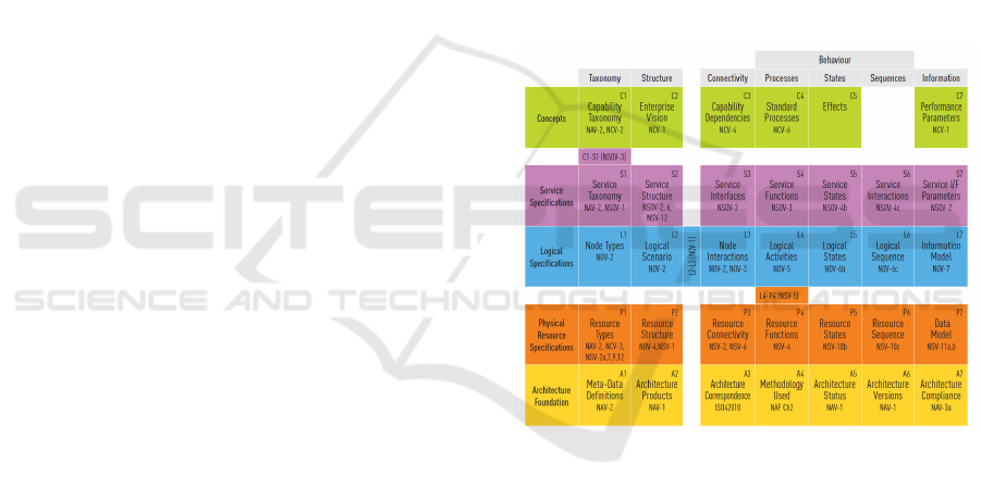
A well organized process of designing a system in ac-
cordance with the NAF involves the development of a
series of diagrams presenting the operation of the sys-
tem at five different levels of abstraction. Each level
is related to a perspective from which the designer
looks at the system, that is: Concepts, Service Spec-
ifications, Logical Specifications, Physical Resource
Specifications and Architecture Meta-Data.
The above-mentioned perspectives are presented
in Fig. 1.
Figure 1: NAFv4 Viewpoints (ref. (Architecture Capability
Team, 2018).
A complete system description does not always re-
quire the creation of all 44 types of diagrams. Often,
around 15-20 views are needed to obtain a compre-
hensive set of information about the system. In next
part of this publication, only the abbreviated view
names will be used. They can be found in the upper
right corners of the elements presented in Fig. 1.
In the case of design work related to the devel-
opment of a UAV mission execution system, the de-
sign process should begin with collecting a set of re-
quirements from the user. It must define the opera-
tion of the system in all possible situations and de-
termine what input data will be available for the pro-
cesses implemented in the system and determine the
output data received after their completion. Opera-
tional requirements for the entire system should also
ICSOFT 2021 - 16th International Conference on Software Technologies
136

be included e.g. in use case diagrams under the C1
view. Use cases can be categorized by the nomen-
clature related to colors proposed by A. Cockburn in
(Cockburn, 2000):
• White - the most general, in relation to the entire
system in the context of its use in the organization.
Example: using the UAV system to detect enemy.
• Blue - more detailed than white, the level of func-
tions available to the user. Example: using EO\IR
turret to locate hidden objects of an enemy.
• Indigo - defining the details of using the system
within its specific functions. Example: selecting
a thermal imager as the active vision sensor of the
EO\IR turret.
• Black - the lowest level, related to the way the sys-
tem performs specific functions. Example: send-
ing the ChangeCamera command with the IR ar-
gument to the EO\IR turret.
As an example of a contextual perspective, dia-
gram C1 should only include white use cases. This
perspective can be supplemented with an analytical
diagram showing the system as a block which is
processing specific input requests into specific out-
put products (C2 diagram). An activity should be
specified for each white use case. All activities can
be presented collectively in the diagram of activities
C3. Following the NAF methodology, each activity
should be detailed with an activity diagram represent-
ing C4 views. Such diagrams should contain com-
ponent processes associated with the blue use cases
dedicated to them.
The level of blue use cases in NAF is related to
the system’s logic perspective. These cases should
be presented in the L1 use case diagrams. When de-
signing the UAV system, a L4 activity diagram should
be developed for each of them, presenting the activ-
ities carried out by all the users involved in realiza-
tion of the specific function of the system. The di-
agrams should contain horizontal partitions assigned
to system users carrying out specific component activ-
ities. The most important activities should be related
to indigo-level use cases. The logical perspective can
be supplemented by diagrams showing the data mod-
els used - L7 diagrams. The system description can
also be extended by sequence diagrams that imple-
ment L6 views, presenting the interaction between the
system elements at the logical level. It is also worth
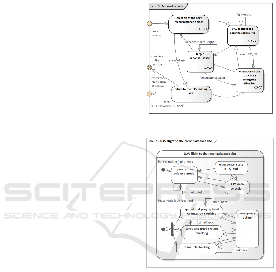
developing L5 state diagrams (see Fig. 2). They are
particularly useful in modeling systems where several
processes are performed concurrently. State diagrams
can easily present system’s states and the transitions
between them within the selected activities. State dia-
grams are particularly useful in modeling real-time or
near-real-time systems.
Defining indigo-color use cases allows to easily
transit to the definition of the NAF service perspec-
tive. Indigo use cases should be presented in S1 di-
agrams. Each use case represents a single activity of
the system, so it should be listed in the appropriate di-
agram of S4 activity. These diagrams differ from the
similar L4 diagrams in that there should already be
only two partitions (in the vertical arrangement): the
first one associated with the user performing the activ-
ity, the second one with the modeled system. Black
use cases can link this perspective directly with the
perspective of physical resources. They should be
linked to selected, more complex system activities.
At the service level, there is also a requirement for
a precise definition of transitions between the states
of individual system components. Therefore, the S5
diagrams should be extended and the individual func-
tions of the system should be detailed (see Fig. 3).
Defining the perspective of physical resources
should start with the presentation of all black use
cases in the diagrams of the P1 view. For the needs
of configuration management, a set of P2 diagrams
should also be developed to present the physical com-
ponents that make up individual system elements,
such as a Ground Control Station, UAV or a mobile
terminal for a payload operator. The P2 view should
also include diagrams presenting software compo-
nents (applications, packages, libraries, etc.), and if
necessary, also the classes and data structures they
contain. The physical connections of the components
with the specification of the standards used (e.g. Eth-
ernet) and ports should be presented in the deploy-
ment diagrams of the P3 view. The P3 view should
also include diagrams showing the logical connec-
tions of the components. These diagrams should de-
tail the logical interfaces of the components. They can
make a future implementation process significantly
easier to supervise. The perspective of physical re-
sources should be supplemented by a set of P6 se-
quence diagrams showing the flow of information be-
tween the components specified in P2.
When designing unmanned aerial platforms, ap-
propriate design of user interfaces is also required.
These interfaces must meet the standards described
in the documents standardizing the design of such
systems and the UAV approval processes for flights.
These are standards such as STANAG 4703 (NATO,
2016), 4671 (NATO, 2019), DO-178C (RTCA SC-
205, 2011), DO-254 (RTCA SC-180, 2000) and oth-
ers that relate to the method of designing unmanned
systems. The NAF methodology is in this case a set
of structured system design rules that will allow for a
positive transition of the system certification process.
Designing Operational Safety Procedures for UAV According to NATO Architecture Framework
137
Due to the scope of the article, it is not possible to
describe the detailed guidelines specified in the stan-
dardization documents. We refer the interested user to
these documents (for example (RTCA SC-205, 2011)
or (RTCA SC-180, 2000)). However, it is worth men-
tioning that the above-mentioned standards define, for
example, the way of designing the system and the way
of conducting the testing process, for which a detailed
design is needed.
3 DESIGNING OPERATIONAL
SAFETY PROCEDURES
Due to the volume of the article, it is not possible to
present the use of NAF in the project implemented
by the authors of the article in the area of unmanned
aerial platforms. Only the most important models that
are used will be presented. The main emphasis was
placed on the presentation of models showing the dy-
namics of the system, which is crucial in the case of
UAVs. Hence, state, activity, and sequence diagrams
are primarily discussed.
First of all, it should be emphasized that in
projects related to the construction of unmanned plat-
forms operating in near real-time (e.g. UAV plat-
forms), the basic models of the NAF logical level (L
level) are system state models. System state models
in the form of state diagrams (sometimes called state
machines) reflect the abstract division of a system into
states in which it can be.
Since the system is always in some state that char-
acterizes the current set of system variable values,
the development of state diagrams gives designers the
opportunity to better decompose the system into its
component parts (Delligatti, 2013). This is shown in
the Fig. 2, which shows the basic states of the UAV,
which include, among others, the flight to the indi-
cated reconnaissance object.
The description of each state should include a de-
scription of the operations of all active system com-
ponents. For example, in the described state of flight
to the recognized object, the subsystems of flight
control, control of available sensors (mainly EO/IR,
which tracks the environment in which the platform
operates), automatic fault location, spatial and geo-
graphical orientation are usually active (two of them
are presented in Fig. 3). The operation of each of
these systems should be presented in the form of an
activity diagram of L4 level in NAF methodology. An
example is shown in the Fig.4.
The diagram shows the interaction of the UAV
pilot with the unmanned aerial vehicle. The plat-
form carries out the planned mission in the Waypoint
Figure 2: L5 - State diagram of the mission execution pro-
cess.
Figure 3: L5 - State diagram of the mission execution pro-
cess - details of one of the states.
mode. In this mode, the air platform flies to the next
route points and performs reconnaissance tasks pro-
grammed in the mission. The unmanned platform has
defined in the mission plan what area should be pho-
tographed and what sensor should be used for this.
At any time, the pilot can change the flight mode and
switch to manual control. The same applies to the
payload operator, who can interrupt the programmed
recognition pattern and take control of the EO/IR.
In practice, the modeling of functions in un-
manned aerial platforms should start at the level of
state diagrams that give a picture of the operation
of the entire system. Diagrams showing the activities
ICSOFT 2021 - 16th International Conference on Software Technologies
138
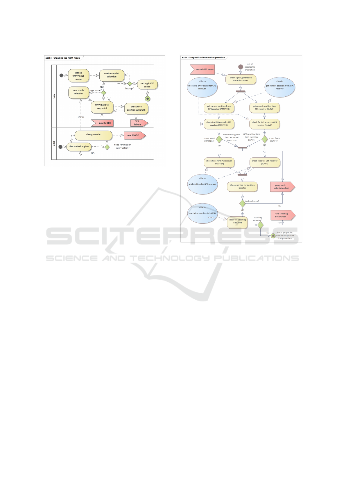
Figure 4: L4 - Activity diagram showing how the pilot
changes the flight mode of the unmanned aerial vehicle.
within individual states should be the result of devel-
oping a state machine model. Fig. 4 shows an exam-
ple of an activity diagram illustrating how to change
the flight mode of a UAV and how to handle possible
problems with GPS operation.
Another element that distinguishes the models of
near real-time systems are the procedures for handling
special situations, including undesirable ones, which
may occur during the flight of the unmanned platform.
The set of these procedures must include at least the
procedures for the UAV response in the event of loss
of communication with the Ground Control Station
(see Fig. 5), and procedures for the platform opera-
tion in the event of loss of spatial orientation due to
GPS jamming or spoofing. Another case of emer-
gency procedures to be implemented are the proce-
dures for actions in the event of loss of spatial ori-
entation due to failure of inertial systems. Each of
these procedures is the more complex, the larger the
unmanned platform it concerns.
An example of S4 diagram for a specific safety
procedure for UAV has been presented in Fig. 5.
The diagram shows actions performed by the sys-
tem in case of loss of geographical orientation. Se-
lected, complex activities are related to black-level
use cases. Checking for GPS data spoofing in coop-
eration with the SAASM module is an important ac-
tivity of the UAV spatial orientation system, so the
process must be modeled on a dedicated sequence
diagram. Fig.6 shows command flow between two
components responsible for realization of the proce-
dure: SAASM software and GPS receiver software.
Similar diagrams should be prepared for all important
data flows realized as a part of selected important
Figure 5: S4 - Activity diagram showing the procedure for
dealing with loss of geographical orientation.
activities. This applies in particular to the procedures
for checking the throughput and condition of the ra-
dio link and the procedures for testing the propulsion
system of the air platform.
In order to complete the model of system’s func-
tionality described in this paper, a list of system com-
ponents as well as logical and physical connections
between them should also be presented. Thus, P2
diagram (Fig.7) presents resource structure of UAV
avionics subsystem. Connections between these com-
ponents can be found in Fig.9 (physical connections)
and Fig.8 (connections between logical interfaces).
The simplified avionics diagram of the system (see
Fig.8) shows the logical connections between the spa-
tial orientation system (two GPS and SAASM sys-
tem), mission computer, flight computer and payload
which is controlled by the mission computer. The di-
agram shows the devices used to communicate the air
platform position (GPS position) to both computers.
It was assumed that the flight computer has greater
powers to control GPS than the mission computer.
By dividing the system into modules, it is possible to
capture the components that are part of a specific air
Designing Operational Safety Procedures for UAV According to NATO Architecture Framework
139
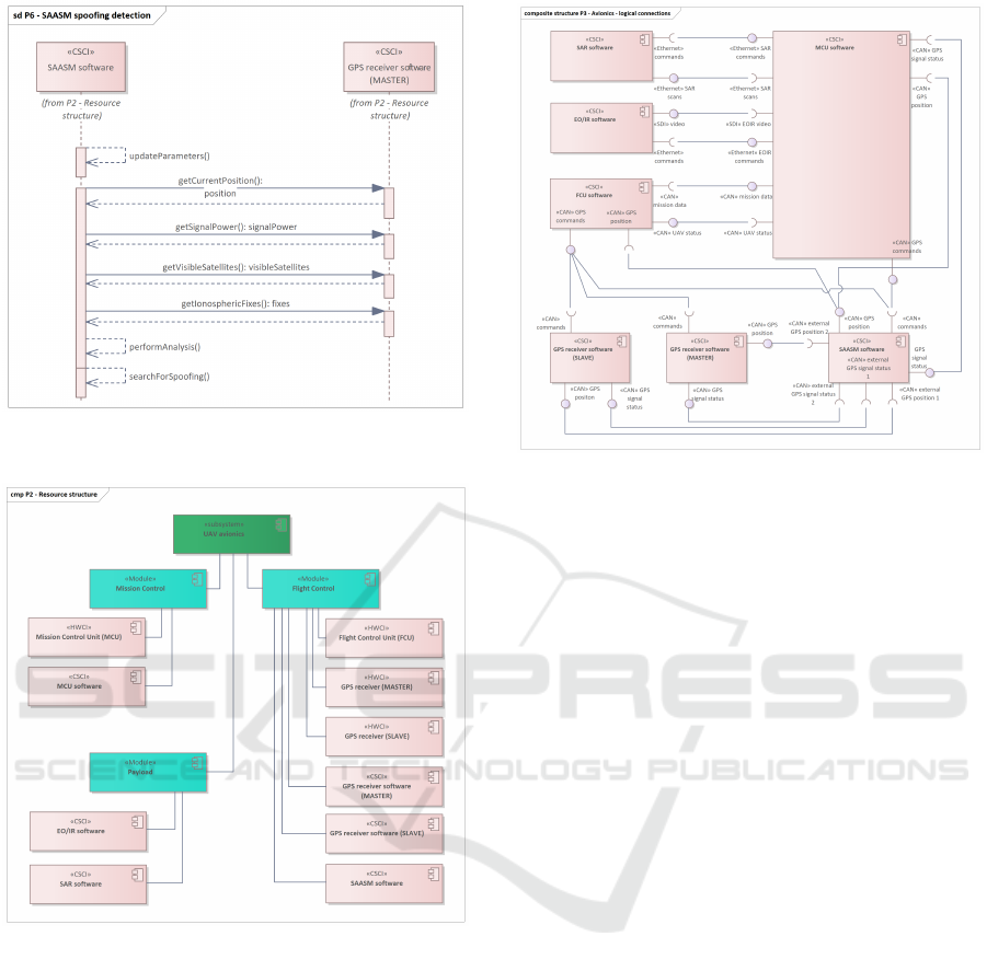
Figure 6: P6 - Sequence diagram showing how spoofing is
detected by the unmanned platform.
Figure 7: P2 - Structure of the unmanned aerial platform
resources divided into groups: FMS (Flight Management
System), Mission Computer and Payload.
platform subsystem. On very complex, multi-device
platforms, resource diagrams play an important role.
They allow designers to check if the description of the
functionality of any of the platform devices has been
omitted.
Payload control is performed entirely by the mis-
sion computer which also has a complete mission plan
saved within. The mission plan includes such items
as a flight plan, payload usage plan, communications
plan, etc. Preparation of a mission plan has been pre-
sented in (Stecz and Gromada, 2020b). The mission
computer takes full control over the mission. On the
other hand, the flight computer is an element that su-
pervises the flight of the platform. Such design ap-
Figure 8: P3 - The main components of the unmanned aerial
vehicle - the logical interfaces among the components.
proach stays line with current best practices in build-
ing unmanned aerial systems.
The most complex element of the system is the
communication between the mission computer and
the flight computer. This requires a detailed design
of the tasks performed by both computers, the divi-
sion of tasks between both computers and the design
of a way for computers to inform themselves about
possible problems with the performance of tasks. For
the unmanned platform, a method of handling all ex-
ceptional situations that may arise during the flight
should be designed. Some of these situations are han-
dled by the mission computer, and some by the flight
computer. Moreover, in the event of a mission com-
puter failure, the flight computer takes over control of
the platform. Depending on the size of the air plat-
form, the tasks of the flight computer after a mission
computer crash may be an emergency return to the
landing site or even a mission continuation within a
certain range.
The physical connections between the UAV com-
ponents are shown in Fig.9. The diagram shows
two basic communication buses in the system: CAN
and Ethernet. Mission and flight computers com-
municate on the CAN bus in accordance with the
CAN Aerospace standard. The CAN bus is also used
to communicate with on-board devices that are di-
rectly controlled by the flight computer, such as ser-
vos and air data computer. SAASM and GPS re-
ceivers are also connected to the CAN bus. In the case
of payload, high-speed lines are required, exceeding
100[Mb/s]. Therefore, Ethernet is used for this type
of communication. The mission computer is equipped
ICSOFT 2021 - 16th International Conference on Software Technologies
140
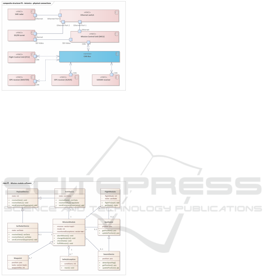
Figure 9: P3 - The main components of the UAV - the data
exchange interfaces among the components.
with high-speed buses and it controls the operation of
the optoelectronic turret and other reconnaissance de-
vices. The element that separates messages sent over
Ethernet is a switch or a router. In the case of smaller
platforms, these are simple switches. On larger plat-
forms, complex communication routers are used. The
device used should be able to configure the multicast
service, which simplifies the management of devices
on the unmanned platform.
Figure 10: P7 - Class diagram presenting basic components
of mission module software.
Last but not least, a logical data model used in sys-
tem software should be presented as an example of
NAF Information (Fig.1) viewpoint. As far as UAV
is concerned, the most complex system module is the
mission module. This piece of software is responsi-
ble for fulfilling the mission, controlling payload de-
vices (EO/IR, SAR, ELINT etc.) and navigation hard-
ware, communicating with flight module and moni-
toring UAV’s state together with handling emergency
situations. Exemplary data model proposed by au-
thors consists of 9 classes and has been presented as
P7 class diagram in Fig.10. The main class, Mis-
sionModule, keeps a mission vector, current flight
mode and a vector of emergencies monitored as its
attributes. It aggregates instances of Waypoint class
(as a part of mission vector) and instances of Safe-
tyExcepion class (vector of emergencies). Each way-
point keeps its geographical position, list of tasks for
payload and an unique ID number. Communication
with payload devices is handled by instances of Sar-
RadarDevice and EoIrDevice classes. They both in-
herit from an abstract PayloadDevice class and share
the same set of operations: sending native commands
to devices, receiving status responses and receiving
reconnaissance data. MissionModule object commu-
nicates with FlightModule object in tasks related with
platform’s steering. GPSDevice and SaasmDevice
classes are responsible for controlling and communi-
cating with UAV’s navigation hardware. The software
implementation should use multiple threads in order
to guarantee UAV’s near real-time responses during
the flight. Similar data models should be prepared for
all software items developed for UAV’s components.
The presented approach in line with the NAF
methodology is in fact similar to other methodologies,
such as Rational Unified Process (RUP), where a lot
of attention is also paid to modeling system dynam-
ics. In contrast to the RUP, the NAF methodology
allows for a simple connection with the standards for
the certification of unmanned platforms. Therefore,
the authors use NAF as their primary design method-
ology.
4 CONCLUSIONS
The article presents the principles of designing un-
manned aerial platforms belonging to the group of
near real-time systems. Principles of designing the
functionality of such systems were proposed based
on the NAF approach. This approach supports the
fulfillment of the certification requirements of flying
systems in accordance with the guidelines DO-178
and DO-254. Particular attention was paid to mod-
eling the system dynamics, which is usually the most
difficult part of designing the functionality of an un-
manned system. The approach was based on sys-
tem state machines that are used in both SysML and
UML. SysML has more extensive modeling mecha-
nisms, which is why it is more often used to model
robots, which include unmanned platforms.
The article omits the issues related to formal mod-
eling of operations with the use of optimization algo-
rithms or algorithms from the Artificial Intelligence
group. Such issues are described in the DO-333
Designing Operational Safety Procedures for UAV According to NATO Architecture Framework
141

Formal Methods methodology, which should be in-
cluded in the certification process of the air platform.
When designing a system based on NAF, the func-
tions that relate to calculation algorithms should be
indicated. For these functions, the algorithm descrip-
tion described in (Stecz and Gromada, 2020b) and
(Stecz and Gromada, 2020a) should be used.
In order to improve readability, the article also
omits the method of modeling the detailed sequences
of commands sent when controlling devices such as
EO/IR from the mission computer. There are usu-
ally complex UML (SysML) constructs in control
sequences that allow you to define loops, optional
or mandatory steps, and conditionally triggered se-
quences. We refer the reader interested in such dia-
grams to the book written by (Delligatti, 2013).
ACKNOWLEDGEMENTS
This work was co-financed by Military University of
Technology under research project UGB 860/2021.
REFERENCES
Architecture Capability Team (2018). Nato architecture
framework ver. 4. Technical report, NATO. ENCLO-
SURE 1, AC/322-D(2018)0002-REV1.
Beard, R. W., McLain, T. W., Nelson, D. B., Kingston, D.,
and Johanson, D. (2006). Decentralized cooperative
aerial surveillance using fixed-wing miniature UAVs.
Proceedings of the IEEE, 94(7):1306–1324.
Cockburn, A. (2000). Writing Effective Use Cases.
Addison-Wesley Longman Publishing, USA, 1st edi-
tion.
Delligatti, L. (2013). SysML Distilled: A Brief Guide to the
Systems Modeling Language. Addison-Wesley Pro-
fessional Publishing Co., Inc., USA, 1st edition.
Dufrene, W. R. (2005). Mobile military security with con-
centration on unmanned aerial vehicles. In 24th Digi-
tal Avionics Systems Conference, volume 2.
Dustin, M. C. (2015). Monitoring parks with inexpensive
UAVs. cost benefits analysis for monitoring and main-
taining parks facilities. Master’s thesis, University of
Southern California.
Gunetti, P., Thompson, H., and Dodd, T. (2013). Au-
tonomous mission management for UAVs using soar
intelligent agents. International Journal of Systems
Science, 44(5):831–852.
Iscold, P., Pereira, G. A. S., and Torres, L. A. B. (2010). De-
velopment of a hand-launched small UAv for ground
reconnaissance. IEEE Transactions on Aerospace and
Electronic Systems, 46(1):335–348.
Karim, S. and Heinze, C. (2005a). Experiences with
the design and implementation of an agent-based au-
tonomous UAV controller. In Proc. of the Fourth In-
ternational Joint Conference on Autonomous Agents
and Multiagent Systems, AAMAS ’05, page 19–26,
NY, USA. Assoc. for Computing Machinery.
Karim, S. and Heinze, C. (2005b). Experiences with
the design and implementation of an agent-based au-
tonomous UAV controller. In Proc. of the Fourth Int.
Joint Conference on Autonomous Agents and Multia-
gent Systems, AAMAS ’05, page 19–26, NY, USA.
Assoc. for Computing Machinery.
Kekec, T., Ustundag, B. C., Guney, M. A., Yildirim, A., and
Unel, M. (2013). A modular software architecture for
UAVs. In IECON 2013 - 39th Annual Conf. of the
IEEE Ind. Electronics Society, pages 4037–4042.
L
´
opez, J., Royo, P., Pastor, E., Barrado, C., and San-
tamaria, E. (2007). A middleware architecture for
unmanned aircraft avionics. In Proc. of the 2007
ACM/IFIP/USENIX Int. Conf. on Middleware Com-
panion, NY, USA. Assoc. for Computing Machinery.
Mademlis, I., Mygdalis, V., Nikolaidis, N., Montagnuolo,
M., Negro, F., Messina, A., and Pitas, I. (2019). High-
level multiple-UAV cinematography tools for cover-
ing outdoor events. IEEE Trans. on Broadcasting,
65(3):627–635.
NATO (2016). Nato standard AEP-83 light unmanned air-
caft systems airwothiness requirements. Technical re-
port, NATO. Ed. B Ver. 1.
NATO (2019). Nato standard AEP-4671 unmanned aircaft
systems airwothiness (USAR) requirements. Techni-
cal report, NATO. Ed. B Ver. 1.
Nekov
´
a
ˇ
r, F. (2019). Optimal trajectory planning for a
quadrotor UAV for autonomous drone race. Master’s
thesis, Czech Technical University in Prague.
Pastor, E., Lopez, J., and Royo, P. (2007). UAV payload and
mission control hardware/software architecture. IEEE
Aerospace and Electronic Sys. Mag., 22(6):3–8.
Quigley, M., Goodrich, M. A., Griffiths, S., Eldredge, A.,
and Beard, R. W. (2005). Target acquisition, localiza-
tion, and surveillance using a fixed-wing mini-UAV
and gimbaled camera. In Proceedings of the 2005
IEEE International Conference on Robotics and Au-
tomation, pages 2600–2605.
RTCA SC-180, E. W.-. (2000). Do-254 design assurance
guidance for airborne electronic hardware. Technical
report, RTCA, Inc.
RTCA SC-205, E. W.-. (2011). Do-178c software consid-
erations in airborne systems and equipment certifica-
tion. Technical report, RTCA, Inc.
Sanchez-Lopez, J. L., Pestana, J., Puente, P., and Campoy,
P. (2016). A reliable open-source system architecture
for the fast designing and prototyping of autonomous
multi-UAV systems: Simulation and experimentation.
J. Intell. Robotics Syst., 84(1–4):779–797.
Stecz, W. and Gromada, K. (2020a). Determining UAV
flight trajectory for target recognition using EO/IR and
SAR. Sensors, 20(5712).
Stecz, W. and Gromada, K. (2020b). UAV mission planning
with sar application. Sensors, 20(1080).
Yuan, C., Liu, Z., and Zhang, Y. (2015). Uav-based for-
est fire detection and tracking using image processing
techniques. In Int. Conf. on Unmanned Aircraft Sys-
tems (ICUAS), pages 639–643.
ICSOFT 2021 - 16th International Conference on Software Technologies
142
