
Multi-mobile Robot and Avoidance Obstacle to Spatial Mapping in
Indoor Environment
Luis Piardi
1,2 a
, Jos
´
e Lima
1,3 b
and Andr
´
e Schneider de Oliveira
2 c
1
Research Center in Digitalization and Intelligent Robotics (CeDRI), Instituto Polit
´
ecnico de Braganc¸a,
Campus de Santa Apol
´
onia, 5300-253 Braganc¸a, Portugal
2
Universidade T
´
ecnol
´
ogica Federal do Paran
´
a - UTFPR, Avenida Sete de Setembro 3165,
80230-901 Curitiba, Paran
´
a, Brazil
3
INESC, Technology and Science, Porto, Portugal
Keywords:
Autonomous Mobile Robot, Gas Sources Detection, Avoidance Obstacle, Fuzzy Control.
Abstract:
The advancement of technology and techniques applied to robotics contributes to increasing the quality of life
and safety of humanity. One of the most widespread applications of mobile robotics is related to monitoring
indoor environments. However, due to factors such as the size of the environment impacting the monitoring
response, battery autonomy, and autonomous navigation in environments with unknown obstacles, they are
still significant challenges in the diffusion of mobile robotics in these areas. Strategy adopting multiple robots
can overcome these challenges. This work presents an approach to use multi-robots in hazardous environments
with gas leakage to perform spatial mapping of the gas concentration. Obstacles arranged in the environment
are unknown to robots, then a fuzzy control approach is used to avoid the collision. As a result of this paper,
spatial mapping of an indoor environment was carried out with multi-robots that reactively react to unknown
obstacles considering a point gas leak with Gaussian dispersion.
1 INTRODUCTION
In the past years, academic research has focused on
the development of autonomous mobile robots. In
this context, several approaches have been explored,
for example, robots in the indoor or outdoor environ-
ment, using representations with static or dynamic ob-
stacles and total, partial or unknown representations
of the environment in which the robot is allocated.
Technological advances and the development of new
techniques and approaches have disseminated mobile
robotics into real problems. Autonomous vehicles are
becoming an essential tool in a wide range of environ-
mental applications that include ambient data acquisi-
tion, remote sensing, and mapping of the spatial ex-
tent of gas leakage (Bayat et al., 2017). The applica-
tions of these mobile agents in inspection of industrial
plants, search for environmental pollutant sources, ex-
plosives, and drugs at airports and harbors are already
realities (Braun et al., 2019; Baetz et al., 2009).
a
https://orcid.org/0000-0003-1627-8210
b
https://orcid.org/0000-0001-7902-1207
c
https://orcid.org/0000-0002-8295-366X
The present work contributes to the research’s ten-
dency in mapping environments contaminated with
toxic substances or harmful gases using mobile robots
to locate the source of leakage or emission, avoiding
the exposure of humans in hazardous environments.
For this, a group of four robots will be used, equipped
with a sensor and moving collectively towards the in-
door source location in a cooperative manner. Obsta-
cles in the environment are unknown, i.e., the robot
does not have information about the obstacles’ layout
and size. The robot control and avoidance obstacle are
performed through a controller based on fuzzy logic.
During the set of robots navigating the indoor envi-
ronment with dynamic obstacles, carrying out the ac-
quisition of the gas concentration, the data is analyzed
to estimate the leak source position.
The Robot Operating System (ROS) was used to
perform tests and validate the proposal of this work. It
is a framework that contains a wide range of libraries
and tools to develop applications for robots(Martinez
and Fern
´
andez, 2013). All the development of this
work was carried out in a simulation environment, us-
ing the Stage Simulator, the C ++ software library that
simulates multiple mobile robots with a low compu-
Piardi, L., Lima, J. and Schneider de Oliveira, A.
Multi-mobile Robot and Avoidance Obstacle to Spatial Mapping in Indoor Environment.
DOI: 10.5220/0010509200210029
In Proceedings of the 11th International Conference on Simulation and Modeling Methodologies, Technologies and Applications (SIMULTECH 2021), pages 21-29
ISBN: 978-989-758-528-9
Copyright
c
2021 by SCITEPRESS – Science and Technology Publications, Lda. All rights reserved
21

tational cost (Vaughan, 2008).
The remainder of this paper is organized as fol-
lows: the next chapter presents a brief review of state
of the art considering methods for the spatial map-
ping of the environment and finding gas leaks, and
then a brief presentation of approaches that use mo-
bile robots with fuzzy logic control to avoid obsta-
cles. Chapter 3 presents the system architecture and
the simulation environment used in this work. Chap-
ter 4 describes the approach adopted to perform the
spatial mapping, namely the robot’s trajectories, the
fuzzy controllers, and the calculations to estimate the
gas’s position. In chapter 5, the results are presented,
and finally, in chapter 6, the conclusions, limitations,
and future work are realized.
2 RELATED WORK
In this section it will be summarized the briefly review
of two topics that this work addresses. The first of
these will be indoor gas mapping and detection. The
second topic deals with fuzzy logic for the control and
avoidance of dynamic and unknown obstacles using
mobile robot.
2.1 Distribution Mapping and Gas
Leakage Detection
There are several ways to get the gas or toxic distribu-
tion map in a determined contaminated environment.
The most common approach uses stationary sensors,
installed in strategic locations, fixed to posts or walls
(Kroll et al., 2009). It is a standard approach for mon-
itoring environments that have the risk of gas leak-
age and can be found even in homes and other build-
ings (propane and butane based gas detection and
smoke detection). Therefore, the gas distribution in-
formation is only valid for a limited space around the
gas sensor’s location. For this approach’s efficiency,
many sensors are required to cover a relatively large
indoor environment efficiently (Fort et al., 2004). An-
other methodology adopted to carry out the gas distri-
bution mapping is to use specialized and adequately
equipped technicians carrying sensors to detect the
harmful substances. In this approach, humans are in
a contaminated environment to explore and map the
substance to locate the emission source.
Considering the limitations of flexibility, robust-
ness and to avoid exposure of humans to high-risk
environments, approaches using autonomous mobile
robots to perform spatial mapping and leakage focus
detection are great alternatives. Therefore, the aca-
demic community has been developing robot proto-
types to explore contaminated environments, such as
(Zakaria et al., 2017; Lilienthal et al., 2009). In this
line of research, numerous works study and present
in detail a spatial dispersion model of gases, as can
be analyzed in (Kowadlo and Russell, 2008; Lilien-
thal and Duckett, 2004; Loutfi et al., 2009; Lilienthal
et al., 2006).
The need for the use of mobile robots occurs
mainly when the gas source is composed of toxic or
explosive gases, need for flexibility or replacement of
sensors, when the gas source occurs in an inaccessi-
ble location, or when a continuous verification of the
environment is necessary (Gongora et al., 2017). Ap-
proaches that use a mobile robot with a gas sensor at-
tached are found in the literature (Piardi et al., 2017;
Braun et al., 2019). However, these have limitations
for large environments due to battery limitations and
delay in the response of gas detection given the size
of the environment. Strategies based on genetic algo-
rithms seek to optimize the robot’s route to perform
more efficient monitoring, however for dynamic envi-
ronments, changes in the environment demand time to
re-calculate the ideal route (Piardi et al., 2018). Multi-
robot approaches for monitoring can map larger en-
vironments and be more responsive to detecting gas
leakage sources.
2.2 Fuzzy Logic Control
Mobile robots have a wide range of use and can be
controlled using telemetry or semi-autonomous and
autonomous approach. For a robot to be fully au-
tonomous and therefore independent of human oper-
ators or users’ decisions, controllers that operate at
their motors’ speeds are required, usually feedforward
controller or feedback controller. In (Pandey et al.,
2017) it is possible to obtain information of different
techniques used to equip robots of autonomy, such as
neural networks, genetic algorithms, and fuzzy con-
trollers. Sensors with a high amount of environment
information have been widely used to avoid collision
with obstacles, as presented in (Morais et al., 2017),
which uses an RGB-D sensor (e.g kinect or intel
real sense) applying Artificial Potential Field to avoid
nearby obstacles. However, approaches based on
RGB-D sensors demand a high computational power
to process all environment around the robot, identify
obstacles and execute a path free of collision.
In particular, for this work, the fuzzy control ap-
proach will be used, which was introduced by Zadeh
(Zadeh, 1975). It is widely adopted to control the
speed applied to the robot’s wheels to control three-
dimensional coordinates involved i.e. [x, y, θ]. Fuzzy
logic is especially useful for robot controllers, and re-
SIMULTECH 2021 - 11th International Conference on Simulation and Modeling Methodologies, Technologies and Applications
22
searchers present different approaches to control the
robot with fuzzy logic (Vinogradov et al., 2019; Ave-
lar et al., 2020; Mousavi, 2015). The approach pro-
posed in this work uses two fuzzy controls to oper-
ate the wells robot speed, one without the presence of
obstacles whose input is the position of the robot ob-
tained from optometry and the second is active when
an obstacle is detected near to the robot, whose input
is the distance and direction of the obstacle.
3 SETUP AND SYSTEM
ARCHITECTURE
For the present work, the ROS was used as the frame-
work to control four mobile robots Pioneer model
P3-DX with a differential drive. Each robot was
equipped with Hokuyo laser scanner model URG-
04LX to obtain information about the environment
and unknown obstacles. The test and validation en-
vironment was developed in the Stage simulator. This
software presents a realistic model of the 3D environ-
ment, representing the dynamic constraints in real ap-
plications. This environment has 400 squared meters
where it is distributed different unknown obstacles by
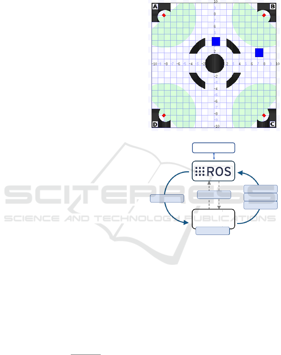
the robots. Figure 1a shows the simulation environ-
ment where the blocks in black are walls, in blues are
obstacles that can be moved and in red arranged in
the corners of the environment are the robots. Figure
1b shows the proposed system architecture describing
the data flow.
The data obtained from the simulator (pose from
dead reckoning, gas data and laser scan data) are pro-
cessed in a project developed in python. The multi-
robots are controlled to perform a defined trajectory,
aiming the exploration of the environment and ac-
quisition of gas concentration data. At the end of
the trajectory, the stored gas data are plotted show-
ing the gas concentration at the points visited by the
robots. As the objective of this work is not to propose
a new method for gas dispersion, the adopted model is
generic and simplified (Kowadlo and Russell, 2008),
not taking into account wind intensity and orientation,
temperature and chemical characteristics of gas parti-
cles. Equation (1) presents the model of gas disper-
sion in the adopted environment, whose behavior is a
Gaussian function.
Z(x, y) = A ·e
−
(x−x
0
)
2
+(y−y
0
)
2
2·σ
2
(1)
The variable Z indicates the concentration of gas,
while (x;y) the position of the robot. The variable A
represents the height of the curve’s peak. The leakage
position is described as (x
0
;y
0
) and σ (the standard
(a) Stage simulation environment.
CONTROL
POSE
SCAN DATA
GAS DATA
STAGE
SIMULATOR
SETUP
SCRIPT CONTROL
(b) System Architecture.
Figure 1: (a) Simulation environment and (b) architecture
proposed.
deviation) the parameter to control the width of the
“belt”.
4 PROPOSED APPROACH
In this section it will be presented the approach devel-
oped to perform a spatial mapping of gas distribution
in an indoor environment. Initially, the robot’s tra-
jectory will be described, covering a region enough
to map the environment. Then, the approach of the
fuzzy controller to follow the path and avoid the un-
known obstacles is presented and finally a mathemati-
cal model to estimate the position of the source of gas
emission.
Multi-mobile Robot and Avoidance Obstacle to Spatial Mapping in Indoor Environment
23
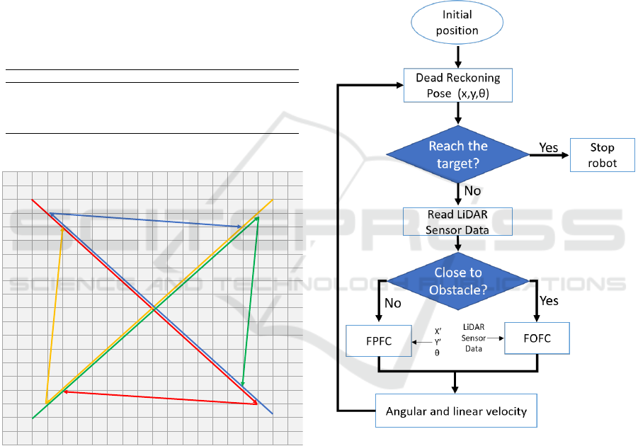
4.1 Robot’s Trajectory
Considering that performing a complete coverage of
the environment with a large size may require a sig-
nificant amount of time and is limited to battery ca-
pacity of the mobile robots. The proposed trajectory
aims at an alternative to perform the data acquisition
for spatial mapping. The simulation environment has
the dimension of −10 to 10 meters in both the X coor-
dinate and the Y coordinate. Table 1 shows the initial,
intermediate and final position for each robot. With
this trajectory, the robots tend to perform a diagonal
crossing in the environment and then move clockwise
direction, ending the trajectory, illustrated by the Fig-
ure 2.
Table 1: Trajectory waypoints (x;y) for each robot.
Robot Initial Position Intermediate position End position
A (-8 ; 8) (7 ; -7) (-6 ; -6)
B (8 ; 8) (-7 ; -7) (-6 ; 6)
C (8 ; -8) (-7 ; 7) (6 ; 6)
D (-8 ; -8) (7 ; 7) (6 ; -6)
ROBOT A
ROBOT B
ROBOT C
ROBOT D
0
-10 0 10
10
Figure 2: Trajectories for robots to explore the environment.
It is worth mentioning that deviations from the ini-
tial trajectory can occur due to the existence of un-
known obstacles. With this arrangement, all portions
of the environment will have sample gas concentra-
tion data.
4.2 Fuzzy Logic Control
The goal of fuzzy logic control is to generate linear
and angular velocity, which will be converted through
ROS to velocities for both the mobile robot’s right and
left motor. To the robots navigate and find their tar-
get while avoiding obstacles, an approach using two
fuzzy controllers has been developed. This approach
was inspired by (Faisal et al., 2013), changing the use
of a sonar sensor to a LiDAR, making it possible to
extract more information from the environment and,
consequently, completely modify fuzzy memberships
and rules. The first one is free path fuzzy control
(FPFC). The second one logic is free obstacle fuzzy
control (FOFC), triggered when the scan laser sensor
detects an obstacle inside a radius of 1 meter from
the robot. Figure 3 illustrates the fuzzy controller of
FPFC and FOFC through a flowchart.
Figure 3: Flowchart of fuzzy logics for robot control.
4.2.1 Free Path Fuzzy Control
FPFC is proposed to move the robot to target points
smoothly. The inputs of FPFC are the distance from
the robot to the target and the angle between the robot
and the target (error angle) as shown in Figure 4.
The outputs of FPFC are linear and angular speed
of the mobile robot. FPFC is implemented with 3
membership functions for each input as illustrated in
Figure 5 and Figure 6. The fuzzy control rules for
these two inputs and two outputs for control the lin-
ear and angular velocity are shown in Table 2.
The velocities (linear and angular) of the mobile
SIMULTECH 2021 - 11th International Conference on Simulation and Modeling Methodologies, Technologies and Applications
24
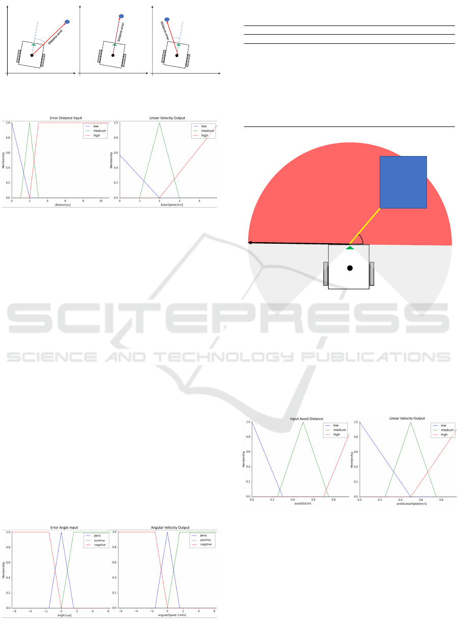
Target
Negative
angle error
Target
Zero angle
erro
Target
Positive
angle error
X
Y
Y
X
X
Y
Figure 4: Cases related to distance and negative, zero and
positive angles for FPFC.
Figure 5: Input membership functions for the distance error
and membership functions for the linear velocity.
robots are calculated using the defuzzification step.
Note that in this work, the centroid defuzzification
technique has been adopted.
4.2.2 Free Obstacle Fuzzy Control
The FOFC enters the scene in place of FPFC when
the laser scan detects some obstacle within 1 meter of
the distance around the robot (0 to 180
o
). In this con-
trol methodology, the robot does not collide with un-
known obstacles in the environment, generating linear
and angular velocities so that the robot’s trajectory is
free of collisions. Figure 7 shows the used method on
how the inputs to the fuzzy logic are obtained.
This logic consists of two inputs and two out-
puts. The first input represents the shortest distance
between any obstacle and the robot (yellow line in
Figure 7), while the second input indicates the angle
of the line representing this shortest distance from the
robot and the obstacle. The outputs of FOFC are the
linear and angular velocities. FOFC is implemented
with three membership functions for distance (input
and output) illustrated in Figure 8. For the angular
Figure 6: Membership functions for the angle error and
membership functions for the angular velocity.
Table 2: Fuzzy rules of the linear and angular velocity of
the robot in FPFC.
Input Output
Distance Error Angle Error Linear Velocity Angular Velocity
low zero low zero
low positive low positive
low negative low negative
medium zero medium zero
medium positive medium positive
medium negative medium negative
high zero high zero
high positive high positive
high negative high negative
1 m
don't care
don't care
Input Avoid Angle
Input Avoid
Distance
Obstacle
Figure 7: Illustration for the input values for the FOFC.
input, five membership functions are used, while for
the output, three functions are used illustrated in Fig-
ure 9. The rule of FOFC for these two inputs and
two outputs for control the linear and angular veloc-
ity avoiding obstacle is shown in Table 3.
Figure 8: Input membership functions for the distance to
avoid obstacle and membership functions for the linear ve-
locity.
4.3 Algorithm to Find the Gas Source
Considering equation (1) which simplifies the behav-
ior of the gas dispersion in a Gaussian function and
the fact that the robot, while following its trajectory,
records position data and its gas concentration, math-
ematically it is possible to estimate the position of the
Multi-mobile Robot and Avoidance Obstacle to Spatial Mapping in Indoor Environment
25
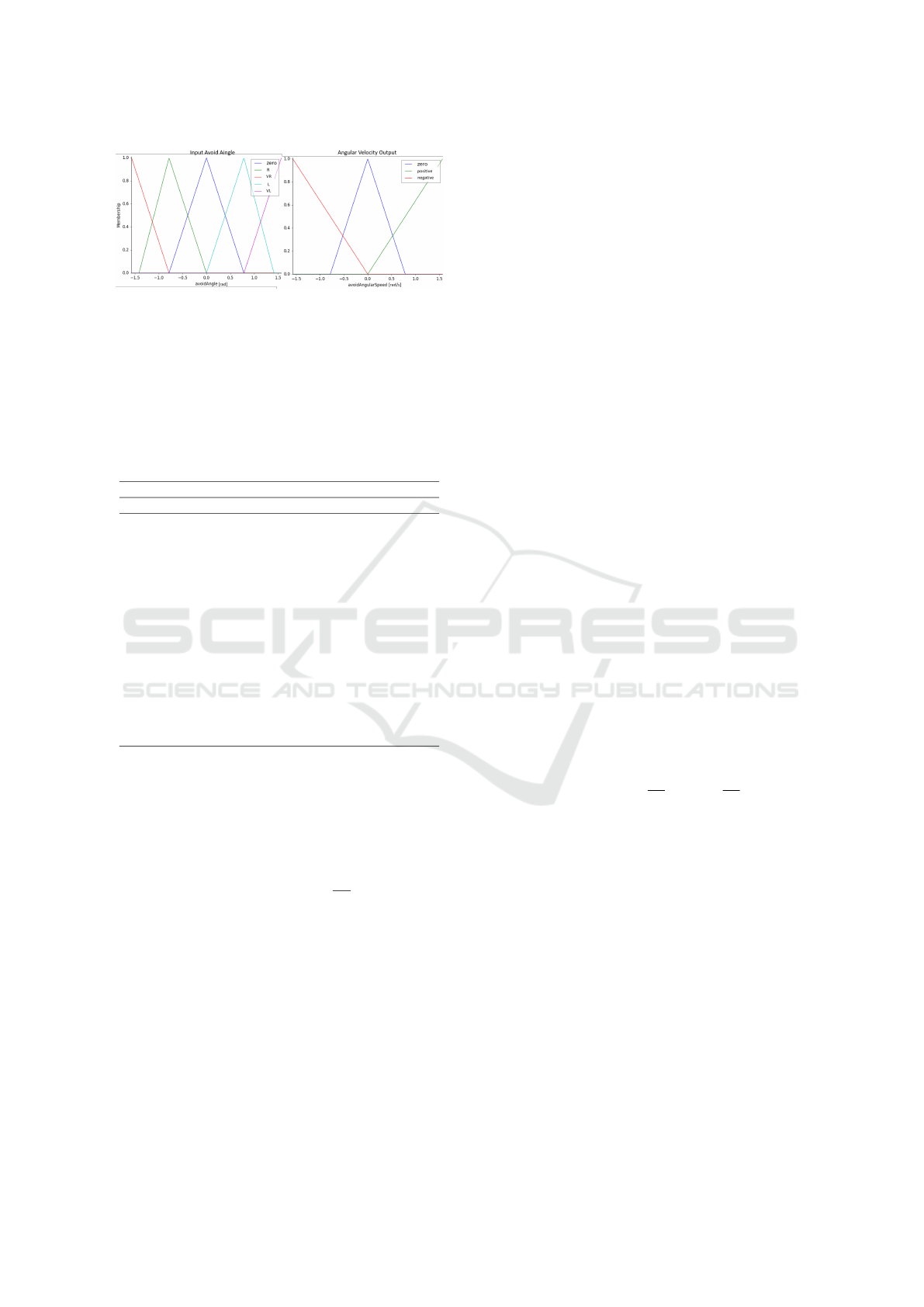
Figure 9: Membership functions for the angle to avoid ob-
stacle and membership functions for the angular velocity.
source with the stored gas concentration data from
each robots. After completing the entire trajectory,
each robot will contribute with the highest gas con-
centration obtained Z and the position (x, y) of this
measurement.
Table 3: Fuzzy rules of the linear and angular velocity of
the robot in FOCF.
Input Output
Distance Angle Linear Velocity Angular Velocity
low zero medium negative
low E medium negative
low D medium positive
low ME medium zero
low MD medium zero
medium zero medium negative
medium E medium negative
medium D medium positive
medium ME medium zero
medium MD medium zero
high zero medium negative
high E medium zero
high D medium zero
high ME medium zero
high MD medium zero
Then, it is possible to use the Linear Least Squares
estimation to find the (x
0
, y
0
) gas emission origin,
with Z concentration measure.
lnZ = ln A + B(x
2
− 2xx
0
+ x
2
0
+ y
2
− 2yy
0
+ y
2
0
) (2)
From equation 2, where B = −
1
2σ
2
, and rearrang-
ing the parcels, results on the equation (3)
lnZ = B(x
2
+y
2
)−2Bx
0
x −2By
0
y +lnA +B(x
2
0
+y
2
0
)
(3)
The model for the Linear Least Square is found in
equation (4).
w = α
1
u
1
+ α
2
u
2
+ α
3
u
3
+ α
4
u
4
(4)
The Linear Least Square variables represent the
following system values:
α
1
= B
α
2
= −2Bx
0
α
3
= −2By
0
α
4
= ln A + B(x
2
0
+ y
2
0
)
w = ln Z
u
1
= x
2
+ y
2
u
2
= x
u
3
= y
u
4
= 1
α = (U
T
.U)
−1
.U
T
.W (5)
α =
α
1
α
2
α
3
α
4
(6)
W =
w
1
w
2
.
.
.
w
n
(7)
U =
u
11
u
21
u
31
u
41
u
12
u
22
u
32
u
42
.
.
.
.
.
.
.
.
.
.
.
.
u
1n
u
2n
u
3n
u
4n
(8)
The matrices in equation (5) are defined in equa-
tions (6), (7) and (8) assuming n measures,where n
indicates the number of robots, and in this case n = 4.
After the estimation the gas emission origin (x
0
, y
0
)
can be found by the expressions in equation (9).
B = α
1
, x
0
= −
α
2
2B
, y
0
= −
α
3
2B
(9)
Therefore, after applying the maximum values of
gas concentration obtained by each robot during the
execution of its defined trajectory, in the Linear Least
Square model to obtain the values of α
1
a1, α
2
, α
4
,
and α
4
, and substitute these variables in equation 9,
the source of the gas leak x
0
and y
0
is estimated.
5 RESULTS
In order to present the results of this work, the ap-
proach described above with four robots was per-
formed in the STAGE simulator, a multi mobile robot
simulator contained in ROS, to obtain samples of gas
concentration data in an environment of 20 X 20 me-
ters. Figure 10 shows the gas distribution in the envi-
ronment according to equation 1 with the gas source
SIMULTECH 2021 - 11th International Conference on Simulation and Modeling Methodologies, Technologies and Applications
26
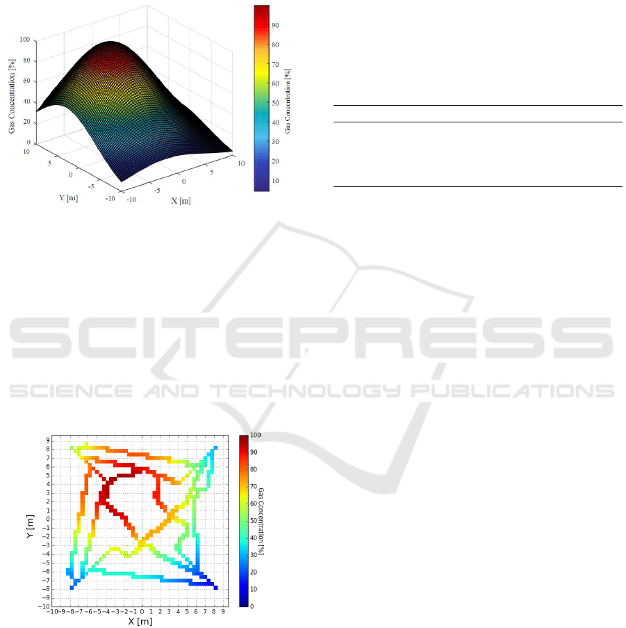
located at the position x
0
= -2 and y
0
= 3.It is possi-
ble to observe the Gaussian behavior of the gas con-
centration throughout the environment, which decays
exponentially as it moves away from the source of the
gas leak in any direction.
Figure 10: Gaussian distribution of gas in an indoor envi-
ronment, source of gas located at position x
0
= -2 and y
0
=
3.
Figure 11 shows the gas samples collected by the
robots during their path as described in section 4.1.
The multiple mobile robots carry out the trajectory
simultaneously. Even robots do not perform all the
scanning of the environment, it is possible to observe
that at some moment of the defined path, some robot
will pass near to a point with a high concentration of
gas (whatever it is), which is enough to estimate the
position of the gas source.
Figure 11: Robots detection of gas in the indoor environ-
ment, source of gas located at position x
0
= -2 and y
0
= 3.
Figure 12 divides the trajectory into 6 scenarios.
Scenario 1 shows the start point of robots A, B, C, and
D with the handle sensors (circle in green) according
to Table 1. They start at the intermediate point ac-
cording to the FPFC algorithm. In scenario 2, it is
possible to identify that due to the presence of un-
known obstacles detected by the LiDAR sensor, the
FOFC controller is active, and there were no colli-
sions, and the robots start to bypass the obstacles in
the region of nearly 1 meter of distance. Scenario 3
and 4 is a region that alternates between the two con-
figurations (FPFC or FOFC) according to the robot’s
position. In scenario 5, all robots are already at the
intermediate point towards the endpoint (scenario 6),
predominantly controlled by the FPFC rules.
Table 4: Data obtained by the robots to estimate the position
of the gas leak.
x [m] y [m]
Gas Conc. (Z) [%]
Robot A 0.939 -1.731 72.861
Robot B -1.430 5.828 91.858
Robot C -3.847 3.399 96.421
Robot D -2.32 4.84 96.490
The complete trajectory executed by the robots to
reach the target avoiding obstacle can be seeing in
the complementary video available at: https://tinyurl.
com/tpysdbf5.
The position (x, y) where each robot detected the
highest gas concentration, as well as the percentage
of this concentration is described in Table 4. After
applying the logarithmic calculation to the Z concen-
tration values and obtaining the w values of each robot
to construct the W matrix (equation 7) and the calcu-
lations with (x, y) positions to obtain the variables u
1
,
u
2
, u
3
and u
4
, doing this for each robot and then ob-
taining the U matrix (equation 8) to result in the val-
ues of α (equation 5 and 6) the system of equation is
then solved (equation 9), resulting in the position of
the gas leak source x
0
= -2 and y
0
= 3.
6 CONCLUSIONS AND FUTURE
WORKS
In this work, a multi-robot system was developed in
ROS using STAGE simulator, to carry out the scan-
ning in high risk indoor environments, which objec-
tive is to obtain a spatial mapping of the gas con-
centration. The fuzzy system proposed for the work,
namely FPFC and FOFC based in the Lidar sensor
distance data, proved to be efficient, since the robots
do not collide with unknown obstacles and managing
to cross tight spaces between two distinct obstacles.
Considering the simplification of gas dispersion in the
environment, it was possible to simulate its distribu-
tion and, applying the Linear Least Squares model
presented, estimate the position of the gas leak source.
Multi-mobile Robot and Avoidance Obstacle to Spatial Mapping in Indoor Environment
27
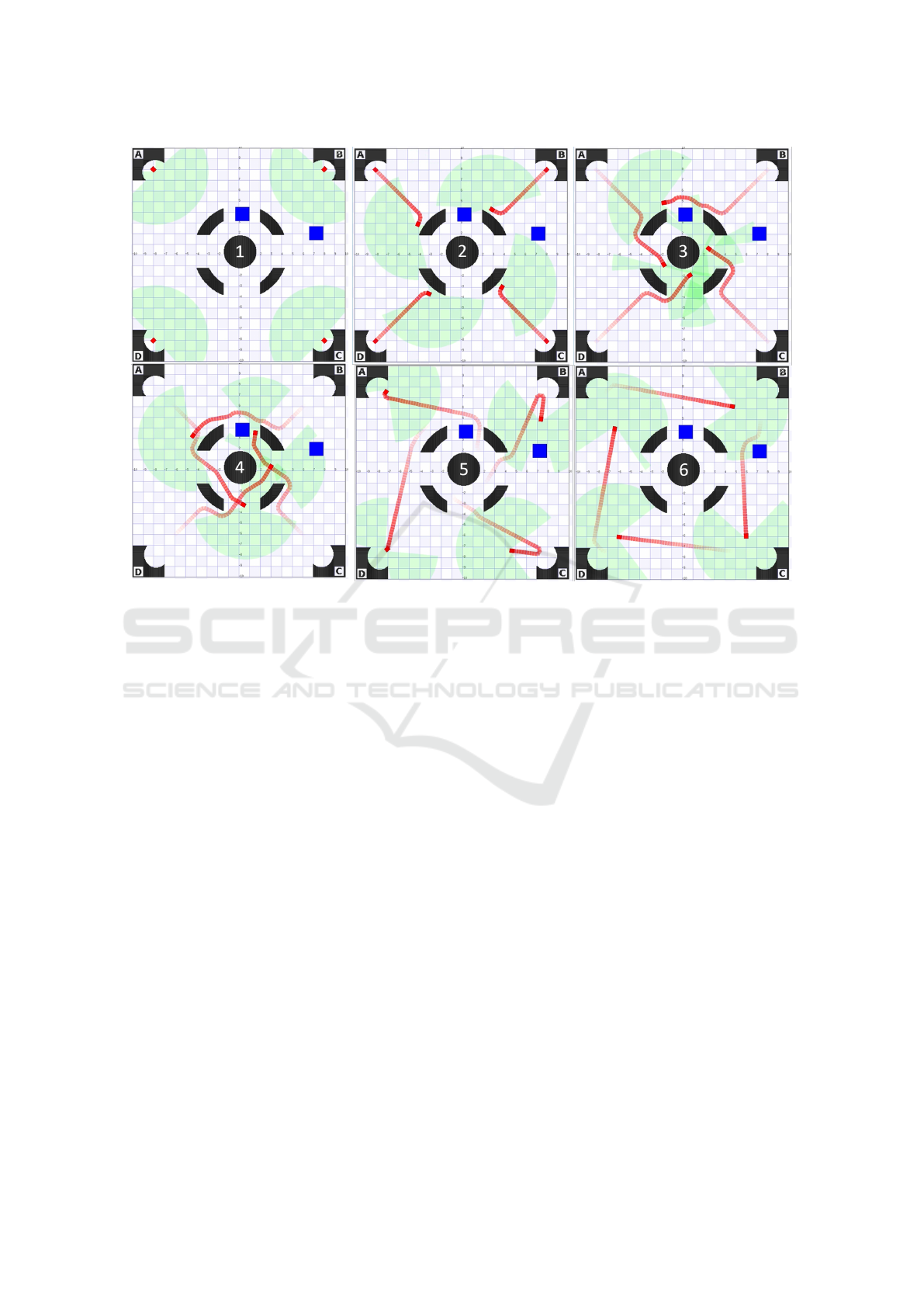
Figure 12: FPFC and FOFC algorithm to multi robot free collisions navigation in the environment with unknown obstacles.
The known limitations of this work will be ex-
plored in future works, such as interference and noise
in the use of several laser sensors with similar char-
acteristics and frequency bands and calibration and
delay correction in multi-robot systems. More com-
plex gas distribution models will also be implemented
in future works, considering the effect of wind, tem-
perature, and particle characteristics, adapting the gas
leak source’s pose estimation technique. Finally, as
the interaction between robots to optimize space ex-
plored and monitored in the indoor environment, task
allocation policies and data exchange regarding gas
concentrations in the scanned area by each robot.
ACKNOWLEDGMENT
This work has been supported by FCT- Fundac¸
˜
ao
para a Ci
ˆ
encia e Tecnologia within the Project Scope:
UIDB/05757/2020. Additionally, this work was
supported in part by the National Counsel of Techno-
logical and Scientific Development of Brazil (CNPq),
in part by the Coordination for the Improvement of
Higher Level People (CAPES).
REFERENCES
Avelar, E., Castillo, O., and Soria, J. (2020). Fuzzy logic
controller with fuzzylab python library and the robot
operating system for autonomous mobile robot navi-
gation. Journal of Automation Mobile Robotics and
Intelligent Systems, 14.
Baetz, W., Kroll, A., and Bonow, G. (2009). Mobile robots
with active ir-optical sensing for remote gas detection
and source localization. In 2009 IEEE International
Conference on Robotics and Automation, pages 2773–
2778. IEEE.
Bayat, B., Crasta, N., Crespi, A., Pascoal, A. M., and
Ijspeert, A. (2017). Environmental monitoring us-
ing autonomous vehicles: a survey of recent searching
techniques. Current opinion in biotechnology, 45:76–
84.
Braun, J., Piardi, L., Brito, T., Lima, J., Pereira, A.,
Costa, P., and Nakano, A. (2019). Indoor environ-
ment monitoring in search of gas leakage by mobile
robot. In Iberian Robotics conference, pages 339–350.
Springer.
Faisal, M., Hedjar, R., Al Sulaiman, M., and Al-Mutib, K.
(2013). Fuzzy logic navigation and obstacle avoid-
ance by a mobile robot in an unknown dynamic envi-
ronment. International Journal of Advanced Robotic
Systems, 10(1):37.
Fort, A., Serrano-Santos, M., Spinicci, R., Ulivieri, N.,
and Vignoli, V. (2004). Electronic noses based on
metal oxide gas sensors: the problem of selectivity
SIMULTECH 2021 - 11th International Conference on Simulation and Modeling Methodologies, Technologies and Applications
28

enhancement. In Proceedings of the 21st IEEE Instru-
mentation and Measurement Technology Conference
(IEEE Cat. No. 04CH37510), volume 1, pages 599–
604. IEEE.
Gongora, A., Monroy, J., and Gonzalez-Jimenez, J. (2017).
Gas source localization strategies for teleoperated mo-
bile robots. an experimental analysis. In 2017 Euro-
pean Conference on Mobile Robots (ECMR), pages 1–
6. IEEE.
Kowadlo, G. and Russell, R. A. (2008). Robot odor local-
ization: a taxonomy and survey. The International
Journal of Robotics Research, 27(8):869–894.
Kroll, A., Baetz, W., and Peretzki, D. (2009). On au-
tonomous detection of pressured air and gas leaks us-
ing passive ir-thermography for mobile robot appli-
cation. In Robotics and Automation, 2009. ICRA’09.
IEEE International Conference on, pages 921–926.
IEEE.
Lilienthal, A. and Duckett, T. (2004). Building gas concen-
tration gridmaps with a mobile robot. Robotics and
Autonomous Systems, 48(1):3–16.
Lilienthal, A., Loutfi, A., and Duckett, T. (2006). Air-
borne chemical sensing with mobile robots. Sensors,
6(11):1616–1678.
Lilienthal, A. J., Reggente, M., Trincavelli, M., Blanco,
J. L., and Gonzalez, J. (2009). A statistical approach
to gas distribution modelling with mobile robots-the
kernel dm+ v algorithm. In 2009 IEEE/RSJ Interna-
tional Conference on Intelligent Robots and Systems,
pages 570–576. IEEE.
Loutfi, A., Coradeschi, S., Lilienthal, A. J., and Gonzalez,
J. (2009). Gas distribution mapping of multiple odour
sources using a mobile robot. Robotica, 27(2):311–
319.
Martinez, A. and Fern
´
andez, E. (2013). Learning ROS for
robotics programming. Packt Publishing Ltd.
Morais, C., do Nascimento, T. P., Brito, A. V., and Basso, G.
(2017). A 3d anti-collision system based on artificial
potential field method for a mobile robot. In ICAART
(1), pages 308–313.
Mousavi, M. A. (2015). A fast fuzzy path tracking con-
troller for mobile robots. In 2015 3rd RSI Inter-
national Conference on Robotics and Mechatronics
(ICROM), pages 675–680. IEEE.
Pandey, A., Pandey, S., and Parhi, D. (2017). Mobile robot
navigation and obstacle avoidance techniques: A re-
view. Int Rob Auto J, 2(3):00022.
Piardi, L., Lima, J., Costa, P., and Brito, T. (2017). Devel-
opment of a dynamic path for a toxic substances map-
ping mobile robot in industry environment. In Iberian
Robotics conference, pages 655–667. Springer.
Piardi, L., Lima, J., Pereira, A. I., and Costa, P. (2018). Path
planning optimization method based on genetic algo-
rithm for mapping toxic environment. In International
Conference on Bioinspired Methods and Their Appli-
cations, pages 223–233. Springer.
Vaughan, R. (2008). Massively multi-robot simulation in
stage. Swarm intelligence, 2(2-4):189–208.
Vinogradov, A., Terentev, A., Kochetkov, M., and Petrov, V.
(2019). Model of fuzzy regulator of mobile robot mo-
tion control system. In 2019 IEEE Conference of Rus-
sian Young Researchers in Electrical and Electronic
Engineering (EIConRus), pages 2109–2112. IEEE.
Zadeh, L. A. (1975). The concept of a linguistic variable
and its application to approximate reasoning—i. In-
formation sciences, 8(3):199–249.
Zakaria, A. H., Mustafah, Y. M., Abdullah, J., Khair, N.,
and Abdullah, T. (2017). Development of autonomous
radiation mapping robot. Procedia Computer Science,
105:81–86.
Multi-mobile Robot and Avoidance Obstacle to Spatial Mapping in Indoor Environment
29
