
Stiffness Modeling of Compliant Serial Manipulators based on
Tensegrity Mechanism under External Loading
Wanda Zhao
1
, Anatol Pashkevich
1,2
and Damien Chablat
1,3
1
Laboratoire des Sciences du Numérique de Nantes (LS2N), UMR CNRS 6004, Nantes, France
2
IMT Atlantique Bretagne Pays de la Loire, Nantes, France
3
Centre National de la Recherche Scientifique (CNRS), France
Keywords: Compliant Manipulator, Tensegrity Mechanism, Stiffness Analysis, Robot Buckling.
Abstract: The paper focuses on the stiffness modeling of a new type of compliant manipulator and its non-linear
behavior under external loading. The manipulator under study is a serial mechanical structure composed of
dual-triangle segments. The main attention is paid to the possible equilibriums and the manipulator stiffness
behavior under the loading for the initial non-straight configuration. It was demonstrated that there is a quasi-
buckling phenomenon for this manipulator while the external loading increasing. In the neighborhood of these
configurations, the manipulator behavior was analyzed using the enhanced Virtual Joint Method (VJM).
Relevant simulation study confirmed the obtained theoretical results.
1 INTRODUCTION
Compliant manipulators are used nowadays in many
fields due to their flexibility, modularized
construction, and low weight. A lot of new
mechanical structures were studied in this area
(Frecker, Ananthasuresh et al., 1997; Albu-Schaffer
et al., 2008; Wang and Chen, 2009; Howell, 2013),
which showed quite good performances compared
with traditional rigid robots. Recently, in literature
particular attention is paid to tensegrity mechanisms,
which are made up of a series of similar segments
composed of compressive and tensile elements
(cables or springs) (Skelton and Oliveira, 2009;
Moored, Kemp, et al., 2011). One of such structures
is studied in this paper.
Stiffness properties of some tensegrity
mechanisms have been already studied carefully. In
(Arsenault and Gosselin, 2006), the authors
considered the mechanism composed of two springs
and two length-changeable bars. They analyzed the
mechanism stiffness using the energy method,
demonstrated that the mechanism stiffness may
decrease under external loading with the actuators
locked, which may lead to the “buckling”
phenomenon. Also, in (Furet, Lettl and Wenger,
2018), the cable-driven X-shape tensegrity structures
were considered; here the authors investigated the
influence of cable lengths on the mechanism
equilibrium configurations, which may be both stable
and unstable. The relevant analysis of the equilibrium
configurations as well as the stability and singularity
study can be found in (Wenger and Chablat, 2019).
For robotics, similar to classical mechanics
dealing with the Euler column, the buckling is usually
treated as an undesirable phenomenon, because the
robot may suddenly change its shape when the
loading force exceeds some critical value. However,
such property can be useful in some fields (Yamada,
Mameda, et. al., 2010). Also, sometimes the quasi-
buckling phenomenon may occur, which changes the
robot resistance in one direction suddenly while the
external loading is increasing. It is not typical for
robotics and was rarely studied before. For this
reason, this phenomenon should be obligatory taken
into account in stiffness analysis.
This paper is an extension of our previous results
(Zhao, Pashkevich et al., 2020 & 2021), which
concentrated on the stiffness analysis of the simplest
manipulator composed of two and three segments. It
was assumed that each segment is a composition of
two rigid triangle parts, which are connected by a
passive joint in the center and two elastic edges on
each side with controllable preload. In contrast to the
previous results, here we consider a general case with
an arbitrary number of segments, and its stiffness
behavior under the loading.
254
Zhao, W., Pashkevich, A. and Chablat, D.
Stiffness Modeling of Compliant Serial Manipulators based on Tensegrity Mechanism under External Loading.
DOI: 10.5220/0010506102540262
In Proceedings of the 18th International Conference on Informatics in Control, Automation and Robotics (ICINCO 2021), pages 254-262
ISBN: 978-989-758-522-7
Copyright
c
2021 by SCITEPRESS – Science and Technology Publications, Lda. All rights reserved
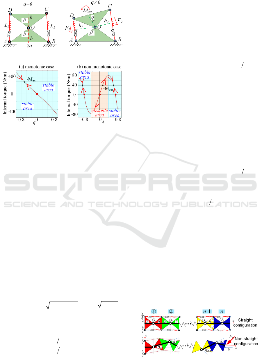
Figure 1: Geometry of a dual-triangle mechanism.
Figure 2: The torque-angle curves of dual-triangle
mechanism.
2 MECHANICS OF A SINGLE
SEGMENT
Let us present first a single segment of the compliant
serial manipulator under study. It consists of two rigid
triangles connected by a passive joint whose rotation
is constrained by two linear springs as shown in
Fig. 1. It is assumed that the mechanism geometry is
described by two triangle parameters (a, b), and the
mechanism shape is defined by the central angle q,
which is adjusted through two control inputs
influencing on the springs L
1
and L
2
. Let us denote the
spring lengths in the non-stress state as
0
L ,and the
spring stiffness coefficient as k.
The mechanism configuration angle q
corresponding to the given control inputs
0
L can be
computed through the static equilibrium equation of
this mechanism, which can be easily derived using the
forces generated by the springs:
0
()
iiii
FkLL=−
,
where the lengths
i
L
are computed using the
formulas
() 2 2cos( )
ii
Lq c
θ
=+
,
22
cab=+
,
1
2 q
θ
β
=+
,
2
2 q
θ
β
=−
, and
atan( / )ab
β
=
. It can
be proved that the torques generated by the springs
can be obtained as the following form.
02
11
02
22
() (1 ()) sin(2 )
() (1 ()) sin(2 )
M
qkLLqc q
M
q k LLq c q
β
β
=+ − +
=− − −
(1)
where
k
denote the springs stiffness coefficients,
L
1
(q) and L
2
(q) are the spring lengths,
0
L are control
inputs, while c and
β
are the geometric parameters
described above (see Fig. 1). So, taking into account
the external torque M
ext
applied to the moving
platform, the static equilibrium equation for the
considered mechanism can be written as M(q)+M
ext
=0, where M(q)= M
1
(q)+ M
2
(q) and
()
0
2 cos(2 )sin cos( )sin( 2)Mq ckc q L q
ββ
=−
(2)
It should be noted that the static stability of this
mechanism highly depends on the equilibrium
configuration defined by q. As follows from the
relevant analysis, the function M(q) can be either a
monotonic or non-monotonic one (Fig. 2), so the
single-segment mechanism may have multiple stable
and unstable equilibriums, which are studied in detail
in (Zhao, Pashkevich et al. 2020). As follows from the
relevant analysis, the stability condition for this
mechanism can be expressed via the derivative sign
at the zero point, i.e.
()
0
|0
q
Mq
=
′
<
, which is easy to
verify in practice. So, the relevant analytical
expression for the derivative
0
2cos(2 )cos cos c ))2(os(cMkc qL qq
ββ
′
=−
(3)
allows us to present the condition of the torque-angle
curve monotonicity as follows
()
02
21( )Lb ab>⋅−
(4)
This expression is extensively used below.
3 MECHANICS OF
MULTI-SEGMENT
MANIPULATOR
The serial manipulator considered in this paper is
composed of n similar sections connected in series as
shown in Fig. 3, where the left-hand-side is assumed
to be fixed. For the initial straight configuration, the
stiffness properties of this manipulator were studied
in our previous paper, where the buckling
Figure 3: Geometry of a multi-segment manipulator.
Stiffness Modeling of Compliant Serial Manipulators based on Tensegrity Mechanism under External Loading
255
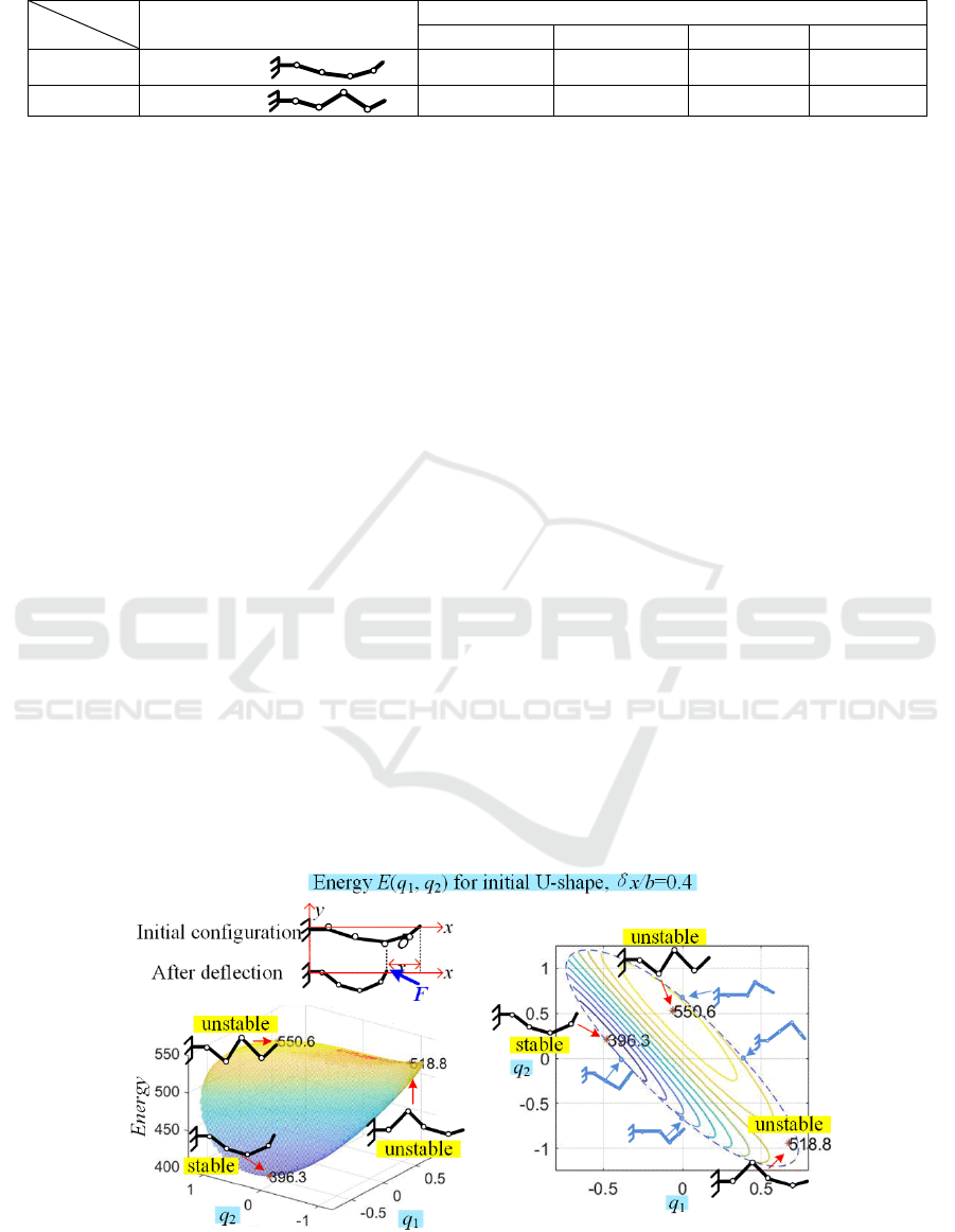
Table 1: Two typical initial configurations of the manipulator for the end-point location (x0, y0) = (7.7b, 0).
Initial shape
Initial confi
g
uration an
g
les
q1 q2 q3 q4
Case #1 U-shape:
‒0.3093 +0.1348 +0.4246 +0.2288
Case #2 Z-shape: ‒0.1136 +0.3768 ‒0.6242 +0.7869
phenomenon (similar to the Euler column) was
discovered and the critical force was computed. In
this paper, a general case is considered where the
initial shape is assumed to be non-straight, and the
stiffness analysis is carried out for the loaded mode.
Let us assumed that the initial configuration of the
n-link manipulator is a non-straight one, which
corresponds to the non-zero angles (
0
0, 1,2,...,
i
qi n≠=
) and the initial end-point
location is
00
(, )(2 ,0)
x
ynbx=⋅−Δ
with 0xΔ> . It
is assumed that the corresponding control inputs
00
12
(, ) 1,2,..,
ii
LL i n=
are computed from the
equilibrium conditions, where
00
1ii
LL=−Δ
,
00
2ii
LL=+Δ
and
0
L
b=
(causing the pre-stress). It is
clear that if
3n ≥ this manipulator is redundant with
respect to the end-effector location control in the (x,
y)-plane. So, for given
00
(, )
x
y
the configuration
angles
0
i
q
cannot be computed in a unique way. For
this reason, we will consider two typical initial shapes
of the manipulator, which in our previous paper were
referred to as the U-shape and Z-shape (Zhao,
Pashkevich et al. 2020). Examples of such initial
configurations for n=4 are shown in Table 1, and their
elastostatic properties will be carefully studied below.
First, let us investigate the force-deflection
relations
()
x
Fx
δ
and
()
y
Fx
δ
corresponding to the
end-effector displacement with
0y
δ
=
, i.e. from the
initial location
00
(, ) (2 ,0)
x
ynbx=⋅−Δ
to the
current one
(, ) (2 ,0)
x
ynbxx
δ
=⋅−Δ−
where
x
δ
is
the end-effector deflection caused by the external
forces
(, )
x
y
FF
and
x
Δ denotes the initial
displacement of the end-effector. Let us apply the
energy method (detailed of this elastic energy were in
Zhao, 2020) allowing us to find possible equilibrium
configurations corresponding to the given
x
δ
. It
should be noted that the geometric constraint coming
from the given end-effector location is
-1
11 1
-1
11 1
2 cos cos 2
2sin sin 0
j
nn
ii x
ji i
j
nn
ii
ji i
bb q b q nbx
bqbq
δ
== =
== =
++=−Δ−
+=
(5)
and allows us to reduce the number of variables in the
energy function
12 2
(, ,... )
n
Eq q q
−
by applying the 2-
link manipulator inverse kinematics to compute the
remaining angles
1
(,)
nn
qq
−
. Further, by detecting the
max/min and saddle points of the function
12 2
( , ,... )
n
Eq q q
−
, it is possible to find the
configuration angles for all possible equilibriums. To
evaluate their stability and compute the external
forces
(, )
x
y
FF
corresponding to the end-effector
Figure 4: The energy function
12
(, )
E
qq
and manipulator equilibriums for initial U-shape configuration (end-effector deflection
δx/b=0.4, δy=0; geometric parameters a/b=1.0; q4>0).
ICINCO 2021 - 18th International Conference on Informatics in Control, Automation and Robotics
256
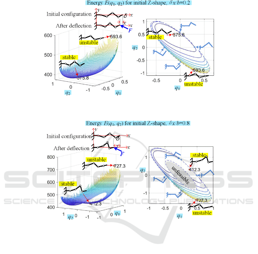
Figure 5: The energy function
12
(, )
E
qq
and manipulator equilibriums for initial Z-shape configuration (end-effector deflection
δx/b=0.2, δy=0; geometric parameters a/b=1.0; q4>0).
Figure 6: The energy function
12
(, )
E
qq
and manipulator equilibriums for initial U-shape configuration (end-effector deflection
δx/b=0.8, δy=0; geometric parameters a/b=1.0; q4>0).
deflection
x
δ
, let us apply the Moore-Penrose
pseudo-inverse on the static equilibrium condition,
which is shown as follows,
1
1
TT
...
q
x
y
qn
M
F
F
M
−
=− ⋅ ⋅
qqq
JJJ
(6)
where both the Jacobian
q
J
and the joint torques
i
M
q
are computed using the configuration angles
i
q
corresponding to the stable equilibriums.
Examples of the obtained energy surfaces for n=4
are presented in Figs 4, 5 and 6, where the end-
effector elastic deflection is
{
}
0.2 , 0.4 ,0.8
x
bbb
δ
∈
and the initial shapes correspond to the end-effector
displacement
0.3
x
bΔ=
(see Table 1). As follows
from these figures, for the initial U-shape (see Fig. 4)
there are two cases of the energy surfaces
12
(, )Eq q
corresponding to q
4
>0 and q
4
<0 which are
symmetrical. Totally, they have 6 critical points; each
of them contains a single maximum, a single
minimum and a single saddle point. Also, their
evolution with respect to
x
δ
is continuous, their
topology remains the same while increasing the
deflection
x
δ
. In contrast, for the initial Z-shape (see
Figs. 5, 6), the energy surfaces
12
(, )Eq q
are quite
different, their evolution with respect to
x
δ
is
discontinuous. The latter leads to sign-changing of
some configuration angles
i
q
under the external
loading F as shown in the figures (see angle q
1
for
instance). Besides, if the deflection
x
δ
is large
enough as in Fig. 6, the energy surfaces may contain
Stiffness Modeling of Compliant Serial Manipulators based on Tensegrity Mechanism under External Loading
257
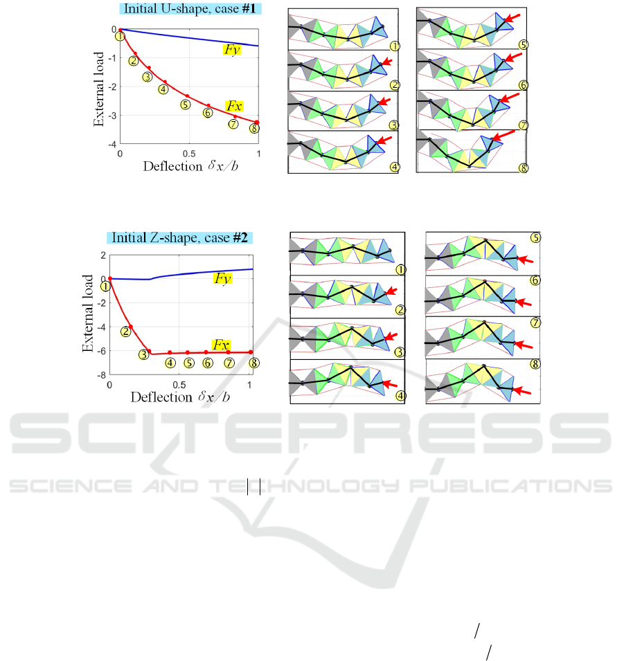
Figure 7: Force-deflection curves Fx(δx), Fy(δx) and manipulator shape changing under the loading for initial U-shape for
(x0, y0) = (7.7b, 0), geometric parameters a/b=1.0 and δy=0.
Figure 8: Force-deflection curves F
x
(δx), F
y
(δx) and manipulator shape changing under the loading for initial Z-shape for (x
0
,
y
0
) = (7.7b, 0), geometric parameters a/b=1.0 and δy=0.
a “hole”, i.e. an unfeasible area, caused by the
violation of the geometric constraints
max
ii
qq≤
inside of the manipulator segments.
4 MANIPULATOR STIFFNESS
UNDER THE LOADING
By applying the above-presented energy method and
computing minimums of the energy function
12 2
( , ,... ) min
n
Eq q q
−
→
for different
x
δ
, it is
possible to obtain the desired force-deflection
relations
()
x
Fx
δ
and
()
y
Fx
δ
describing the
manipulator stiffness properties. Examples of such
computations for n=4 are presented in Figs 7 and 8.
For the initial U-configuration (see Fig. 7), the
change of the manipulator shape is smooth, the
manipulator resistance against the external loading is
gradually increasing while the deflection
x
δ
becomes larger. Also, the stiffness coefficient in the
x-direction is decreasing continuously. This tendency
is observed until the manipulator reaches its
geometric constraints.
In contrast, for the initial Z-configuration (see Fig.
8), there are two intervals of the manipulator
deformation. In the beginning when
x
δ
is relatively
small the manipulator maintains its Z-shape and the
resistance against the external force is monotonically
increasing, similar to the previous case. Further, when
the deflection
x
δ
is larger than some critical value,
the buckling phenomenon is occurring, and the
manipulator resistance against the external force is
not increasing anymore. Correspondingly, the
stiffness coefficient
x
dF dx
becomes very small,
the stiffness coefficient
y
dF dx
changes its sign and
the manipulator does not keep its initial Z-shape
(some of the angles
i
q
change the signs). Finally,
after the buckling, the manipulator moves in the
direction of its internal geometric constraints. Hence,
in practice, it is preferable to use the U-shape of the
manipulator if the task space obstacles (external
constraints) allows. It should be also noted that for the
Z-shape it is necessary to avoid high loadings
exceeding the critical force causing buckling.
Further, in addition to the above presented force-
deflection relations
()
x
Fx
δ
and
()
y
Fx
δ
derived
from the assumption of
varx
δ
= ,
0y
δ
=
, let us
ICINCO 2021 - 18th International Conference on Informatics in Control, Automation and Robotics
258

analyze the changing of the manipulator stiffness
coefficients under the loading
()
,
x
y
FF
without
imposing any kinematic constraints of the end-effector
location. To obtain the desired relations it is necessary
to compute the configuration angles
1
( ,..., )
n
qq
corresponding to the manipulator equilibriums for
different given external forces
()
,
x
y
FF
. It is clear that
these angles can be found numerically by solving the
system of n independent equations
×
=
T
qq
n2
M+J F 0 (7)
describing the static equilibrium condition (by
applying Newton’s method for instance). However,
the initial guess of the angles
00
1
( ,..., )
n
qq
should be
evaluated correctly, to ensure that they are in the
neighborhood of the minimum energy configuration,
because only such cases can be observed in practice.
Such initial guess can be obtained using the above-
presented energy method applied in the space
1
( ,..., )
n
qq
with rather rough grid with large step.
Also, the desired angles corresponding to the external
loading
()
,
x
y
FF
can be found using the Matlab
function fminsearch which minimizes the sum of the
squared residuals i.e.
2
T
12
arg min
nn××
=+⋅
qq
q
qMJF
(8)
where both the internal torques
q
M
and the Jacobian
q
J
depend on the angles
1
( ,..., )
n
qq
. It should be also
mentioned that it is possible to simplify the problem
of the initial guess
00
1
( ,..., )
n
qq
selection by gradually
increasing the forces
()
,
x
y
FF
and using solutions
from the previous loaded-equilibrium as the initial
guess for the next one corresponding to
()
,
x
xy y
FFFF+Δ +Δ
. However, when the forces
()
,
x
y
FF
approach the buckling point, the initial
guess from the previous step is not suitable because
the configuration angles are changing essentially and
only the straightforward energy method allows to
obtain the correct initial guess.
5 EVOLUTION OF STIFFNESS
COEFFICIENTS
If the equilibrium configuration angles
1
( ,..., )
n
qq
corresponding to the given force
()
,
x
y
FF
are
computed, it is possible to find the desired stiffness
coefficients using the formula for the loaded case,
()
1
1
T
−
−
=−
Fqqgq
KJKKJ
(9)
that includes two essential components, the first of
which
q
K
corresponds to the unloaded case, and the
second one
g
K
describes the external force influence
on the stiffness. In this expression, the
n×n matrix of
the joint elastic stiffness coefficients
1
( ,..., )
eq eqi
diag K K=
q
K
can be computed using the
segment torque equilibrium equation from section 2,
which yields
()
22
00 00
12 12
2cos
cos sin
2222
i
ii
eq
i
i
ii i
kb a q
LL qLL q
kb
K
a
=− −
+−
−−
(10)
It should be stressed that here, the control inputs
0
1i
L
and
0
2i
L
are constant values, which correspond to the
initial unloaded joint angles
i
q
.
The second matrix
g
K
containing the stiffness
coefficients caused by the loading is symmetrical and
can be computed as
T
i
q∂∂⋅
g
KJ F
, which gives us
the following formula
21 11 2 1
21
...
... ... ...
... ...
x
ynxny
nx ny
J
FJF JFJF
J
FJF
−+ −+
=
−+
g
K (11)
where
J
ij
denotes the element of the Jacobian matrix
J
q
with the ith row and jth colomn.
It is obvious that when the external forces are
equal to zero, the stiffness matrix expression is
reduced to the form, which is known from the
unloaded mode analysis
1
1T
0
−
−
=
qqq
KJKJ
. It should
be also mentioned that, in contrast to the classical
n-
link serial manipulators, here the diagonal matrix
q
K
is configuration dependent (not constant) because
each initial configuration with the angles
1
( ,..., )
n
qq
produces its own control inputs
0
1
i
L
and
0
2
i
L
included
in the expression (10). Besides, here the unloaded
compliance matrix
0
C
can be expressed analytically
in the following way
22
11 1
1
22
0
21 2
1
... *
*...
n
qqn
n
qqn
JJ
KK
JJ
KK
++
=
++
C
(12)
To illustrate the practical importance of the
above-presented results, they were applied to the case
Stiffness Modeling of Compliant Serial Manipulators based on Tensegrity Mechanism under External Loading
259
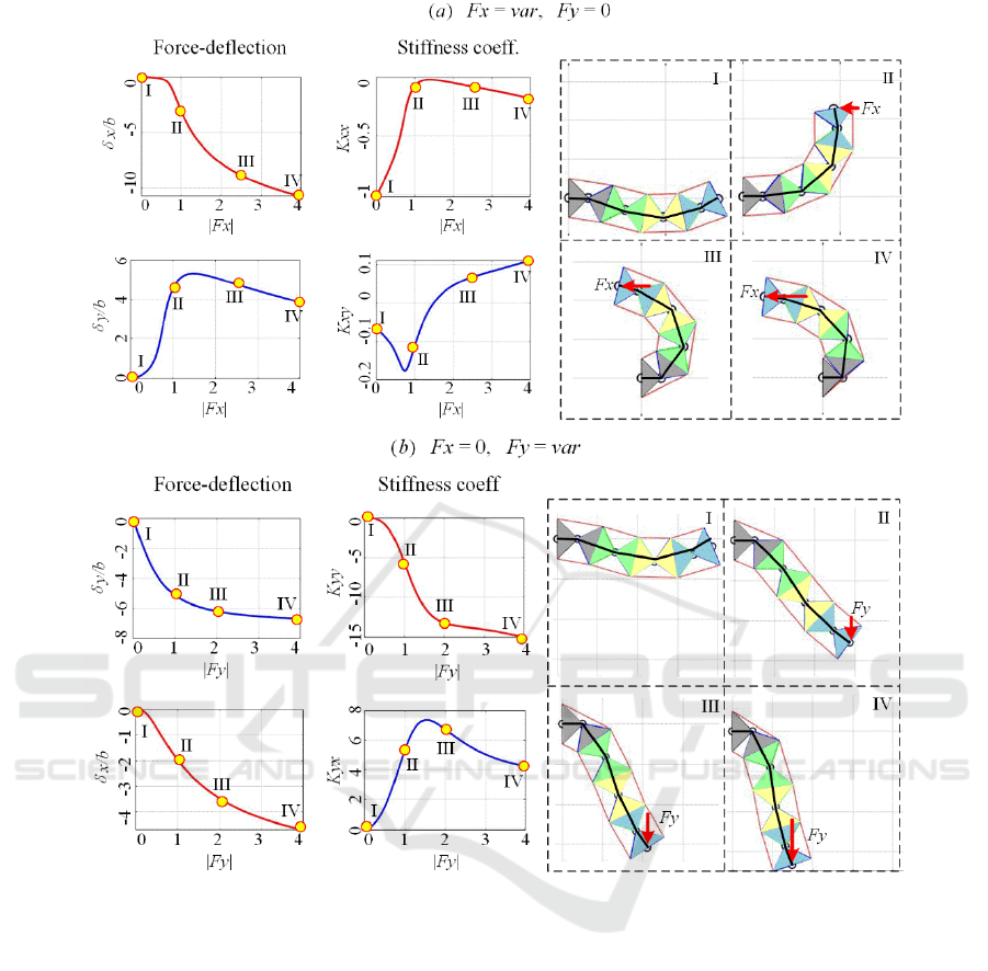
Figure 9: Stiffness coefficients under the F
x
- and F
y
-loading for initial U-shape configuration with (x
0
, y
0
) = (7.7b, 0) and
geometric parameters a/b=1.0.
n=4 assuming that the initial (unloaded) endpoint
location is
()( )
00
,7.7,0xy b=
, and the initial shape is
either U- or Z- one. The configuration angles under
the loading, corresponding to the external force
()
,
x
y
FFF=
, were computed numerically using the
technique proposed above. Relevant results of the
initial U-shape and Z-shape are presented in Figs. 9
and 10 respectively. As follows from these figures,
the manipulator stiffness essentially changes if the
external loading is applied. For the initial U-shape
case, the absolute value of the manipulator stiffness
coefficient |
K
xx
| decreases first, while the force F
x
is
increasing (see Fig. 9a) , until
F
x
is reaching some
critical value when |
K
xx
| is the minimum, then it
begins to increase slowly. In contrast, the stiffness
coefficient
K
xy
(describing the manipulator reaction in
the
y-direction) changes its sign under the loading.
These stiffness properties can be also interpreted from
the geometrical and physical point of view, using the
right-hand side of the Fig. 9a, which shows the
evolution of the manipulator configuration under the
loading. In general, such manipulator behavior can be
treated as “
quasi-buckling”, because for certain
loading
F
x
the stiffness in both x- and y-direction is
very small. And the manipulator rotates quickly until
one of the segment goes close to its joint limits, where
the equivalent rotational stiffness coefficient is very
low. Hence, in practice, it is necessary to avoid
applying too high loading in
x-direction causing
approaching either to the “
quasi-buckling” or the
joint limits and losing the manipulator stiffness.
ICINCO 2021 - 18th International Conference on Informatics in Control, Automation and Robotics
260
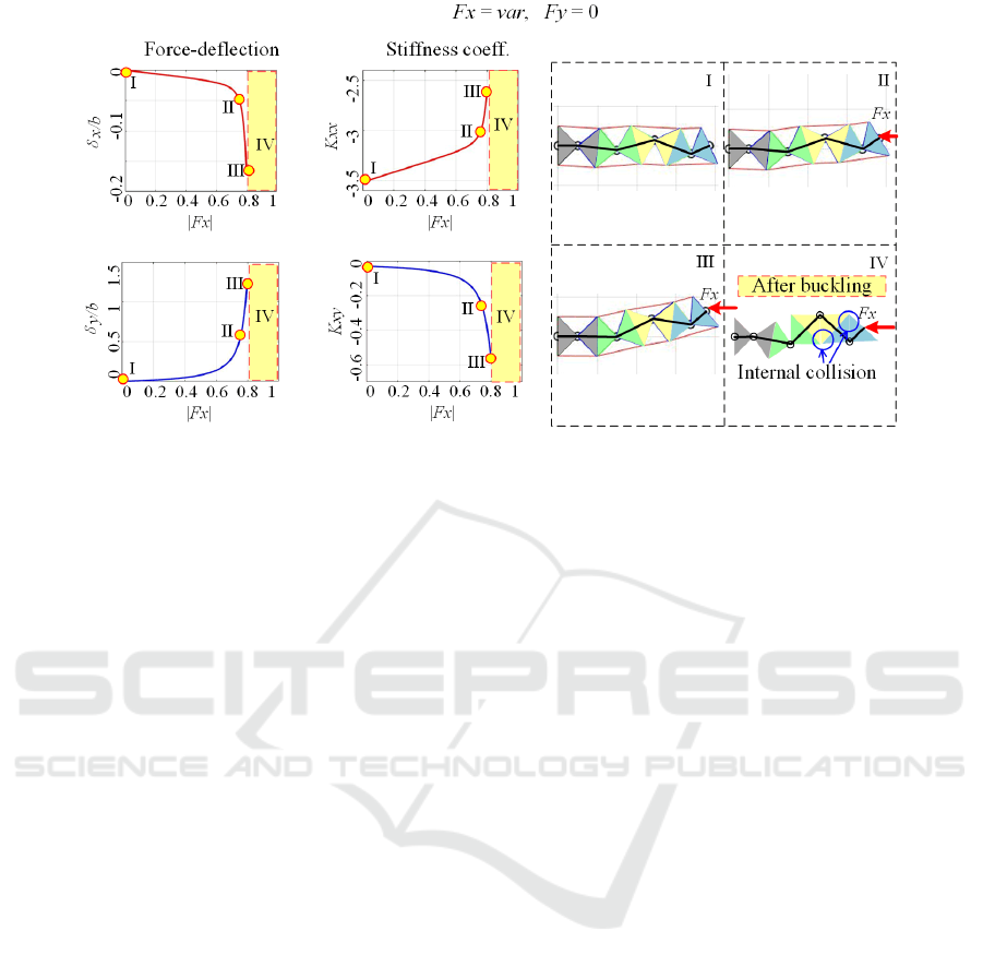
Figure 10: Stiffness coefficients under the F
x
-loading for initial Z-shape configuration with (x
0
, y
0
) = (7.7b, 0) and geometric
parameters a/b=1.0.
On the other side, while increasing the force F
y
(i.e. in the orthogonal direction), the absolute value of
the stiffness coefficient |
K
yy
| is monotonically
increasing first, then it keeps the same tendency
slowly (see Fig. 9b) because of the restriction of the
geometric length of the manipulator. At the same
time, the stiffness coefficient
K
yx
demonstrates non-
monotonic behavior. Such performance can be seen
from the evolution of the manipulator configuration
at the right-hand side of Fig. 9b, where the
manipulator end-point moves towards the extreme
location, as far as possible from the initial one.
Therefore, the high loading in
y-direction should be
also avoided, to prevent from the manipulator
changing its shape change to a pure straight line (see
case IV).
However, for the second case study dealing with
the initial Z-shape, the stiffness properties under the
loading are quite different compared to the U-shape
case. In particular, as follows from Fig. 10, under the
F
x
-loading, the absolute value of the stiffness
coefficient |
K
xx
| decreases gradually at the beginning,
then it decrease quickly to zero. In contrast, the
absolute value of the stiffness coefficient |
K
xy
|
increases monotonically. This phenomenon can be
also treated as “
quasi-buckling” because for certain
loading the manipulator stiffness in
x-direction is
equal to zero, and the stiffness in
y-direction is very
high. These results are illustrated geometrically by
the right-hand side of Fig. 10 showing the evolution
of the manipulator configuration under the
F
x
–
loading. It is clear that here each segment of the
manipulator tends to move close to its geometric
limits before the “
quasi-buckling” is occurring. In this
configuration, even a quite small change of the
external force may lead to large manipulator
deflection, so in practice, it is reasonable to avoid
such situations. It is worth mentioning that the case of
F
y
–loading is not presented in Fig. 10, because it is
quite similar to the U-shape case.
Hence, for the manipulator under study, the
stiffness properties are essentially non-linear with
respect to the loading force. Moreover, if the loading
exceeds a certain value, the stiffness coefficients may
become very low or even change their sign. The latter
may be treated as the
quasi-buckling, which normally
should be avoided.
6 CONCLUSIONS
The paper focuses on the stiffness analysis of a new
type of compliant serial manipulator under the
loading, which is composed of multiple dual-
triangle segments. It is a specific case of the
tensegrity mechanisms that currently are widely
used in soft robotics. The main attention is paid to
the initial non-straight configuration of the
manipulator. It was proved that under the external
loading there may be the quasi-buckling
phenomenon, which suddenly changes the
manipulator resistance in one direction of its
deflection, but may do not influence the resistance
in another direction. It was also demonstrated that
normally there are six equilibrium configurations of
this manipulator (two stable ones and four unstable
ones). But if the deflection of the end-effector is
Stiffness Modeling of Compliant Serial Manipulators based on Tensegrity Mechanism under External Loading
261

large enough some of the equilibriums may be
unfeasible due to the geometric constraints.
To find the possible equilibriums and to analyze
the manipulator shape under the loading, the energy
method was used. Further, the stiffness analysis was
based on the VJM approach allowing to find
linearized relations between the end-effector
deflection and the external force. Relevant simulation
confirmed the obtained results. In the future, this
technique will be used for the development of
relevant control algorithms and related redundancy
resolution.
ACKNOWLEDGEMENTS
This work was supported by the China Scholarship
Council (No. 201801810036).
REFERENCES
Frecker, M. I., Ananthasuresh, G. K., Nishiwaki, S.,
Kikuchi, N., & Kota, S. (1997). Topological Synthesis
of Compliant Mechanisms Using Multi-Criteria
Optimization. Journal of Mechanical Design, 119(2),
238–245. https://doi.org/10.1115/1.2826242
Albu-Schaffer, A., Eiberger, O., Grebenstein, M.,
Haddadin, S., Ott, C., Wimbock, T., Wolf, S., &
Hirzinger, G. (2008). Soft robotics. IEEE Robotics
Automation Magazine, 15(3), 20–30.
https://doi.org/10.1109/MRA.2008.927979
Wang, M. Y., & Chen, S. (2009). Compliant Mechanism
Optimization: Analysis and Design with Intrinsic
Characteristic Stiffness. Mechanics Based Design of
Structures and Machines, 37(2), 183–200.
https://doi.org/10.1080/15397730902761932
Howell, L. L. (2013). Compliant Mechanisms. In J. M.
McCarthy (Ed.), 21st Century Kinematics (pp. 189–
216). Springer. https://doi.org/10.1007/978-1-4471-
4510-3_7
Skelton, R. E., & Oliveira, M. C. de. (2009). Tensegrity
systems. Springer.
Moored, K. W., Kemp, T. H., Houle, N. E., & Bart-Smith,
H. (2011). Analytical predictions, optimization, and
design of a tensegrity-based artificial pectoral fin.
International Journal of Solids and Structures, 48(22–
23), 3142–3159. https://doi.org/10.1016/j.ijsolstr.
2011.07.008
Arsenault, M., & Gosselin, C. M. (2006). Kinematic, static
and dynamic analysis of a planar 2-DOF tensegrity
mechanism. Mechanism and Machine Theory, 41(9),
1072–1089. https://doi.org/10.1016/j.mechmachtheory.
2005.10.014
Furet, M., Lettl, M., & Wenger, P. (2019). Kinematic
Analysis of Planar Tensegrity 2-X Manipulators. In J.
Lenarcic & V. Parenti-Castelli (Eds.), Advances in
Robot Kinematics 2018 (Vol. 8, pp. 153–160). Springer
International Publishing. https://doi.org/10.1007/978-
3-319-93188-3_18.
Wenger, P., & Chablat, D. (2019). Kinetostatic analysis and
solution classification of a class of planar tensegrity
mechanisms. Robotica, 37(7), 1214–1224.
https://doi.org/10.1017/S026357471800070X.
Yamada, A., Mameda, H., Mochiyama, H., & Fujimoto, H.
(2010). A compact jumping robot utilizing snap-
through buckling with bend and twist. 2010 IEEE/RSJ
International Conference on Intelligent Robots and
Systems, 389–394. https://doi.org/10.1109/IROS.2010.
5652928
Zhao, W.; Pashkevich, A.; Klimchik, A. and Chablat, D.
(2020). Stiffness Analysis of a New Tensegrity
Mechanism based on Planar Dual-triangles.
In Proceedings of the 17th International Conference on
Informatics in Control, Automation and Robotics -
Volume 1: ICINCO, ISBN 978-989-758-442-8, pages
402-411. https://doi.org/10.5220/0009803104020411
Zhao, W., Pashkevich, A., Klimchik, A., & Chablat, D.,
2020. The Stability and Stiffness Analysis of a Dual-
Triangle Planar Rotation Mechanism. IDETC-
CIE2020. https://doi.org/10.1115/DETC2020-22076
Zhao, W., Pashkevich, A., Klimchik, A., & Chablat, D.,
(2021). Kinematic Control of Compliant Serial
Manipulators Composed of Dual-Triangles, in 2021
International Conference on Computer, Control and
Robotics (ICCCR), Jan. 2021, pp. 93–97, doi:
10.1109/ICCCR49711.2021.9349285
ICINCO 2021 - 18th International Conference on Informatics in Control, Automation and Robotics
262
